



Selecting a locating pin by catalogue diameter and hardness alone leaves several risks unresolved: the workpiece may not load, its hole may be damaged, or the datum may shift after the pin is replaced. For an assembly, inspection or welding fixture in a Thai factory, define the workpiece datum holes, required positional repeatability, loading method and acceptance test before ordering pins. This guide follows that sequence through round and diamond pin selection, tolerance analysis, replaceability, the request for proposal (RFP) and factory and site acceptance tests (FAT/SAT).
The practical starting point for a flat fixture that locates from two holes is one round primary pin constraining two in-plane directions and one diamond secondary pin constraining one direction. Two close-fitting round pins can require both the workpiece hole spacing and fixture pin spacing to agree within very narrow limits. Manufacturing and temperature variation may then cause binding. The round-and-diamond arrangement is a starting design, not a universal rule; the workpiece geometry, datum scheme, hole form, loads and handling method determine the final choice.
Start with the datum and the result you need to repeat
A fixture may position a part relative to a machining or assembly tool, or it may establish a reference for inspection. Those purposes must be connected to the product drawing. An accurate pin will not prevent a machining offset or a false inspection result if the fixture datum differs from the product datum without a known relationship. Put the product datum surface and holes, fixture supports, two pin roles and clamping direction on one drawing.
ISO 5459:2024 specifies terminology, rules and methods for datums and datum systems in product documentation. Merely citing the standard in an RFP does not specify a fixture. The engineering team must identify the physical features used as datums and how the workpiece drawing is verified. If a convenient process hole is used for loading but final inspection uses another surface, account for that transfer of reference in the process capability study.
Freeze the product drawing revision and review hole diameter, roundness, position tolerance, chamfer, hole spacing, material and coating. A punched hole in sheet metal and a reamed hole must not be treated as equivalent because they share a nominal diameter. Burrs and taper may dominate the first; machining tolerance and cleanliness may dominate the second. If the distribution of production holes is unknown, sample lots rather than designing around a single nominal specimen.
Specify repeatability and loading time separately
“High-precision location” is not an acceptance criterion. Distinguish repeatability after repeatedly removing and loading one workpiece, interchangeability after replacing the pin or fixture, and the final capability of the assembly or measurement process. Derive limits from the product tolerance and check the measuring system separately. A pin’s dimensional tolerance in a catalogue is not the repeatability of an assembled fixture.
Manual loading depends on visibility, access, gloves, the operator’s posture and part mass. Robot loading depends on approach angle, gripper error, part swing and contact speed. Enlarging the clearance may make loading easier but can increase positional variation. Specify both the needed final position and permitted loading time. Test every product variant intended for a common fixture, including variants at the limits of hole size and spacing.
Why round and diamond pins serve different directions
Consider a part resting on a horizontal datum surface with two locating holes. The first round pin establishes X and Y. If the second is also a close-fitting round pin, workpiece hole spacing must closely match fixture pin spacing. Differences from machining, temperature and fixture construction can make the second pin bind, bend the workpiece during loading or wear the hole edge.
A diamond pin retains contact in one direction while relieving the other. Carr Lane describes the round pin as the primary two-axis locator and the diamond as a secondary one-axis locator. MISUMI likewise illustrates a round-and-diamond pair that accommodates small spacing differences and eases loading. These manufacturer explanations provide a design principle, but the orientation of the diamond contact flats and the relieved direction must be drawn for the actual datum line.
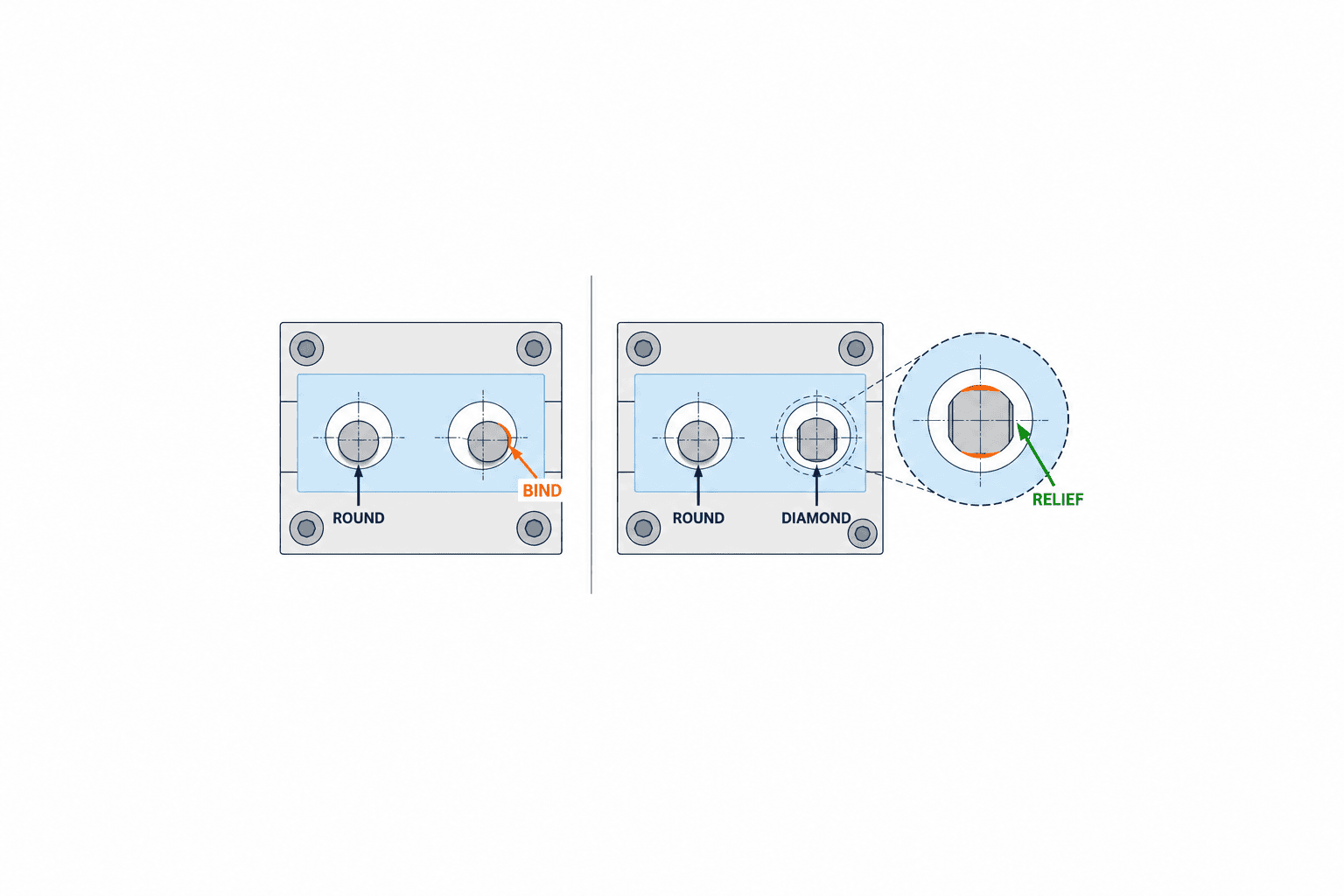
Orient the relief to accommodate spacing variation along the line joining the hole centers. A 90-degree installation error can defeat the intended relief and reduce rotational restraint. Identify the round-pin hole as the primary datum, identify the diamond-pin hole as the secondary datum, and depict the diamond flats in the plan view. Do not leave the orientation as an unwritten shop-floor adjustment; record it in CAD, the assembly drawing and the bill of materials.
With a long workpiece, a small proportional change in temperature or dimensions can produce a substantial absolute spacing change. Greater pin separation can also help control angular position. Neither effect means the pins should simply be placed as far apart as possible. Consider part deflection, loading posture and required clearance. Confirm that the primary hole is consistently produced; placing it on an unstable hole undermines the entire datum chain.
Do not ask pins to replace supports and clamps
Locating pins determine in-plane position. Support pads establish vertical position and orientation, while clamps seat the workpiece on those supports. A clamp acting away from a support can bend a thin part and alter the relationship between its holes and pins. If machining reaction or robotic insertion force is carried mainly by the pin, review the load path through stops, supports and clamps before choosing a thicker pin.
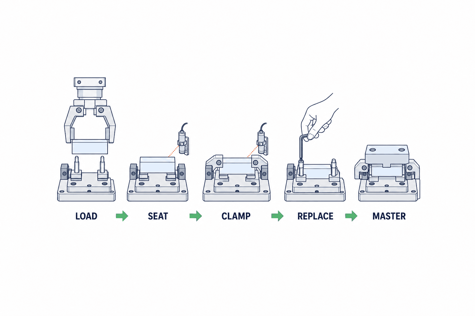
The sequence matters: locate first, then close the clamp. If the clamp contacts early, it may lock the part in the wrong position. If sensors are added, distinguish “pin entered,” “part seated” and “clamp closed” as separate states in the interlock. Our toggle clamp selection guide covers the companion workholding decision.
Calculate hole, pin and positional tolerances together
To select the pin diameter, consider the minimum and maximum workpiece hole size, hole shape, hole positional tolerance, pin diameter tolerance and fixture plate machining error together. ISO 286-2:2010 provides tables of tolerance classes and limit deviations for holes and shafts; selecting a familiar fit designation by itself does not prove that it suits this fixture. A reamed hole and a punched hole, manual top loading and horizontal robotic loading, require different allowances.
As a first approximation, subtract the maximum pin diameter from the minimum hole diameter to obtain minimum diametral clearance. That comparison omits center offset, tilt, burrs, coatings and dirt. With two holes, show how workpiece spacing and fixture pin spacing tolerances combine. Review both ends: can the tightest combination be loaded, and can the loosest combination still meet the positional requirement? If not, reconsider the datum scheme as well as the diamond profile or diameter.
For illustration only, suppose the smallest measured workpiece hole is 10.02 mm and the largest purchased round pin is 10.00 mm. The minimum diametral clearance from size alone is 0.02 mm, equivalent to 0.01 mm radially on one side. An offset beyond that allowance can prevent entry even before considering tilt or chamfers. Reducing the pin diameter until the part loads may increase final position variation. These numbers are a calculation example, not a recommended fit; use the actual hole distribution and product tolerance.
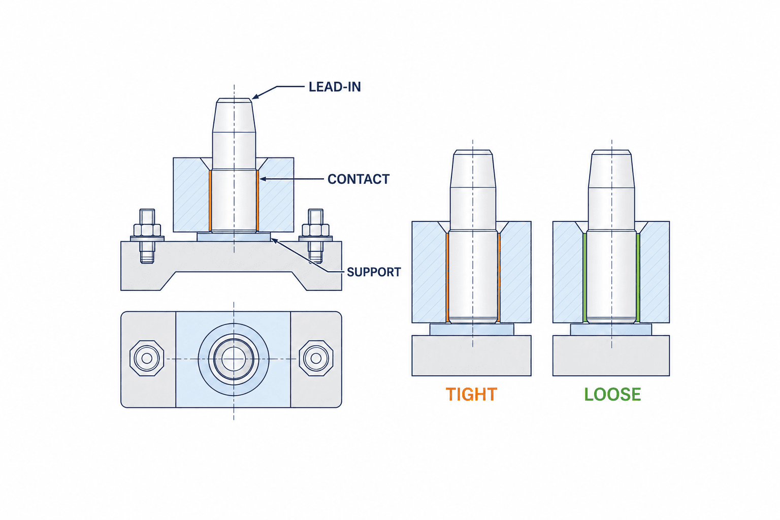
A chamfer or taper at the tip guides initial entry. MISUMI discusses larger lead-in shapes for frequent loading and pins of different heights so that one pin first guides the workpiece. However, a taper that forcibly straightens a thin part can bend it or abrade the hole. The cylindrical locating portion must engage after the lead-in. Video of the entry alone is insufficient; measure position after seating.
Treat thermal expansion as a screening calculation
A Thai plant may move metal parts from a hot receiving area into an air-conditioned inspection room while a welding fixture warms during operation. A first-order expansion estimate is ΔL = α × L × ΔT. If the assumed coefficient is 11.5 × 10^-6/°C, hole spacing is 500 mm and temperature changes by 20°C, the calculated length change is about 0.115 mm. NIST’s gauge-block material offers background on thermal expansion of steel, but the assumed coefficient is not a measured property of a particular part or heat treatment. Confirm actual material and temperatures before using such a calculation in design.
An aluminum workpiece on a steel fixture, or a molded plastic part on a metal plate, may not expand at the same rate as its support. A diamond pin can provide spacing relief; it cannot solve warpage, ovalized holes or movement under clamp load. State the operating temperature, washdown, coolant and chip exposure in the quotation request.
Choose the physical design and its replacement method
A plain pin pressed into a fixture plate is simple. For high-cycle use or frequent changeover, a replaceable arrangement may be more valuable. Carr Lane documents both press-fit styles and renewable lock-screw styles used with a liner bushing. Compare not only the pin price but the time to replace it, method of restoring center location, post-replacement inspection and local spare inventory.
A shoulder can provide a defined stop and a means to accommodate axial loading, but it should not accidentally become a substitute for a properly designed support surface. A rounded or bullet-nose tip helps guide entry when overhead clearance is limited or a robot loads the part. A floating locator may accommodate variation, provided it is clear which degrees of freedom are fixed and which are allowed to move. Verify the choice with actual parts and loads.
Material selection also depends on washdown chemicals, corrosion, welding spatter, chips and permitted surface marking. Hardened steel, stainless steel, coatings and plastic contact elements have different trade-offs. The hardness or concentricity claimed by a manufacturer applies to the specified part number, not every locating pin. Jergens, for example, lists application-specific center and diamond timing pins. Request the drawing and inspection record for the exact part selected.
A replaceable pin needs a repeatable replacement process
Renewable construction does not guarantee that an old pin can be exchanged for a new one without moving the datum. Bushing fit, shank dimensions, keys or anti-rotation features, fastener torque, diamond orientation and shoulder seating all matter. Put photographs and dimensions in the maintenance instruction, and check a master after replacement. Determine a wear limit from actual material and loading cycles; monitor the first production period before fixing the inspection interval.
Do not store round and diamond spare pins in an unlabeled mixed bag. They can share a shank diameter while differing in tip diameter, contact orientation, material or treatment. Record manufacturer, part number, drawing revision, installation position and orientation. Compare life-cycle cost as purchase price plus replacement labor, downtime and reinspection, rather than comparing initial component cost alone.
Manual and robotic loading require different tests
For a manual fixture, consider whether a worker can support the part with one hand, lower it straight onto the pins, see the holes and avoid pinch points. Lead-in geometry, pin height difference and hand clearance matter. A few seconds of insertion resistance can affect both cycle time and fatigue. Test with multiple operators, actual gloves, oil film and production surface finish.
For robotic loading, do not use the pins as a tool to forcibly correct all upstream position error. Combine robot repeatability, gripper error, tray variability and part distortion to estimate initial misalignment. Where necessary, use a coarse mechanical guide or compliance and limit impact velocity at the final pin. Forcing a linear approach after contact can abrade the hole, break a pin and prolong fault recovery.
Use parts at the limits of hole diameter and spacing, lots with likely burrs and parts at different temperatures. Supply and location are separate functions: as in our automatic screw feeder selection guide, define the boundary between presenting the component and accurately locating the workpiece. A locating pin cannot guarantee that the right fastener or component was supplied.
What to include in an RFP for locating pins
“Build a fixture with two pins” leaves the supplier to guess hole tolerances, mounting method and replacement checks. Send the product drawing and revision, CAD data, datum surfaces and holes, required process orientation, annual volume, loading cycles and maintenance conditions. Supply production-representative parts at the tolerance limits, not only an average sample. If prototypes do not have the production hole process, disclose that difference.
Specify primary round and secondary diamond roles, head diameter limits, shank and mounting fit, tip lead-in, protrusion, shoulder, pin spacing, diamond orientation, material, coating, spares and substitution approval. Dimension the fixture plate holes and position tolerance too. A fit designation must state whether it applies to the locating head or mounting shank. ISO 286-2 helps describe size limits; it does not replace an acceptance limit for the assembled fixture.
Design access for the actual replacement tool, pin extraction direction and clearance to adjacent sensors. Include the safety isolation procedure. For a Thai site importing replacement parts, set local minimum stock from actual lead time and usage. A locally available alternative may subtly change tolerance grade or nose geometry; approve substitutions after testing with workpieces.
| Topic | Information to specify | Acceptance evidence |
|---|---|---|
| Workpiece | Drawing revision, material, finish, datum holes and face | Production samples matched to drawing |
| Location | Round primary, diamond secondary, contact direction and supports | Fixture drawing and assembled hardware |
| Dimensions | Hole/pin limits, pin spacing and position tolerance | Part records and assembled measurement |
| Loading | Manual or robot, approach direction and cycle limit | Repeated loading under defined conditions |
| Maintenance | Replacement design, wear rule, spares and instruction | Master measurement after replacement |
| Process quality | Product position tolerance and decision method | Repeated measurement of actual parts |
Compare quotations on a common scope. One supplier may include plate machining and inspection while another expects customer-supplied pins and charges site adjustment separately. Align drawing work, initial setting, spares, FAT, SAT, installation, training and post-start corrections. A “high-precision” catalogue pin does not prove that the finished fixture meets its acceptance conditions.
FAT and SAT: test production variation, not only an ideal part
Agree on the measurement procedure as well as the pass limit. Results change depending on whether pins and holes are cleaned between loadings, whether production oil film is retained, and whether measurements are taken before or after clamping. For CMM checks, map the product datums to the fixture datum in the program. Measuring one point alone can miss rotation around the primary pin; record two or more separated points. Measure the holes of test specimens before FAT to show that boundary parts are represented. If instrument uncertainty approaches the acceptance limit, improve the method before interpreting a small difference as a fixture defect.
At FAT, ask the supplier for measured pin and mounting-hole dimensions, assembled pin position, diamond orientation and material/heat-treatment records. Load actual customer-supplied parts; observe binding, seating, clamp-induced movement and unloading. Record the position spread after repeated load/unload cycles. Keep this result distinct from the component inspection report. An inspection fixture also depends on the measuring instrument and operator. Mitutoyo’s Gage R&R material distinguishes repeatability, reproducibility and stability within a measurement system.
At SAT, repeat relevant tests with local workpieces, gloves, robot program, temperature, oil or chips and final clamp settings. Transport and installation can shift a fixture base. A successful FAT therefore does not eliminate site verification. Including a post-replacement master check in the SAT procedure gives maintenance a reusable template. Include normal shift operators, rather than testing with a single expert alone.
Agree on sample size and acceptance limits from product requirements, lot variation and process risk. “Zero jams in 30 consecutive loadings” is an example of a possible test criterion, not a universal guarantee. Include small holes, large hole spacing, warped datum faces and other boundary specimens. Repeating only an average good part cannot reveal the loading failures likely in production. If scoring or debris appears, add a wear evaluation rather than approving on the short test alone.
Retain part ID, measured hole dimensions, temperature, operator or robot conditions, loading time, position measurements, scratches, stops and recovery time. Save the approved settings and drawing revisions with the record. For quality-critical fixtures, also retain master-gauge status, instrument traceability and measurement location.
Common failures and how to isolate them
Two round pins can work with the first lot yet jam with the next. Compare hole spacing and position tolerance across lots with assembled pin spacing before blaming pin diameter. Changing to a diamond pin will not correct holes produced outside the product specification. A diamond pin installed in the wrong orientation also fails to relieve the intended direction. Use a keyed mounting or unmistakable orientation mark, photographs and consistent drawing views.
Long pin protrusion may make blind loading feel easier, but it increases bending load and breakage risk. Separate the length required for guidance from the length required for final location. A clamp that pushes the workpiece laterally into the pin creates asymmetric wear; review the clamp and support load path. A manual fixture moved directly into a robot cell may fail because a person instinctively wiggles a part into place while a straight robot move cannot. Specify a coarse guide, approach speed, detection and fault stop.
Finally, a replaceable pin without a replacement acceptance procedure is only partially maintainable. A new pin in a worn bushing will not restore the datum. Inspect the bushing, locking screw and seat, then check position with a master. Record adjustments as engineering changes rather than leaving untracked spacers or offsets on the shop floor.
Compare total cost, not the pin’s unit price
Pins are inexpensive relative to a complete fixture but can strongly affect stoppage and defects. Compare initial pin, bushing and plate machining; FAT/SAT; loading time; replacement; remeasurement; rework; and downtime. There is no defensible universal price or payback period because size, specification and location change cost. Quote the same workpiece tolerance, cycle count and acceptance scope to every supplier.
A cheap press-fit pin may have low purchase cost yet require fixture removal and plate repair when worn. A renewable design costs more initially but may save downtime if the Thai maintenance team can replace and verify it rapidly. Use realistic replacement frequency and spare-part lead time. Keep uncertain inputs as a range instead of forcing them into one precise ROI. For broader supplier and fixture cost decisions, see our jig design and manufacturing guide. This article focuses on the pin that physically realizes the workpiece datum.
FAQ: locating pin selection and implementation
Are two round pins always wrong?
No. They may be justified if hole size, spacing, position, temperature and insertion variation are tightly controlled and tests show both loading and final quality meet the requirement. The common two-hole arrangement risks overconstraint, so evaluate a round-and-diamond alternative. Keep the worst-case tolerance review and tests across lots as evidence.
Which way should the diamond pin face?
Orient it to constrain one direction while relieving spacing variation along the line between the hole centers. Draw the pin centers, contact flats and relieved direction in the fixture plan view. Confirm both easy loading and angular and positional repeatability after installation.
Can a smaller pin solve a loading problem?
It may help insertion but can increase positional variation or uneven seating under clamp load. First separate hole-size distribution, spacing, burrs, lead-in geometry, robot posture and clamp sequence. Minimum size clearance alone is insufficient.
How many cycles does a locating pin last?
There is no universal cycle count. Workpiece material, hole edge, loading force, chips, abrasives, lubrication, washdown and coating affect wear. Monitor diameter, surface damage and fixture repeatability during early production; set a replacement threshold from evidence and the chosen manufacturer’s conditions.
What must Thai suppliers receive for comparable quotes?
Provide the product drawing revision, representative parts, datums, cycle and repeatability requirements, yearly loading count, environment, replacement method and FAT/SAT limits on a common basis. A component-only quote cannot reveal the cost of plate machining, site adjustment, tests and spares. If the full product drawing is confidential, issue a controlled purchasing drawing of the datum features and tolerances.
Summary
A locating pin is small, but it is where the fixture physically implements its datum. Design the round primary and diamond secondary contact directions together with the workpiece holes, spacing, supports, clamps and loading process. A purchased pin’s dimensional accuracy and an assembled fixture’s repeatability are separate questions. A common RFP and boundary-part FAT/SAT turn “does it enter?” into a measurable production and maintenance decision.
If your Thai plant is commissioning a fixture or investigating insertion failures, hole measurements, fixture drawings and stop or defect records are enough to begin a useful review. We can help define the round-and-diamond arrangement, renewable construction and acceptance conditions at the concept stage; contact TOMAS TECH.
Primary references
- Carr Lane: Locating Pins — primary round and secondary diamond principle.
- Carr Lane: Types of Locating Pins — shapes, replacement methods and orientation.
- MISUMI: Principles of Positioning — round/diamond pair, staggered heights and lead-in.
- Jergens: 5-Axis Locating Pins — application-specific center and diamond timing pins.
- ISO 5459:2024 — datum systems.
- ISO 286-2:2010 — hole and shaft tolerance tables.
- NIST: The Gauge Block Handbook — thermal expansion in dimensional metrology.
- Mitutoyo: MeasurLink Gage R&R — measurement-system repeatability and reproducibility.


