


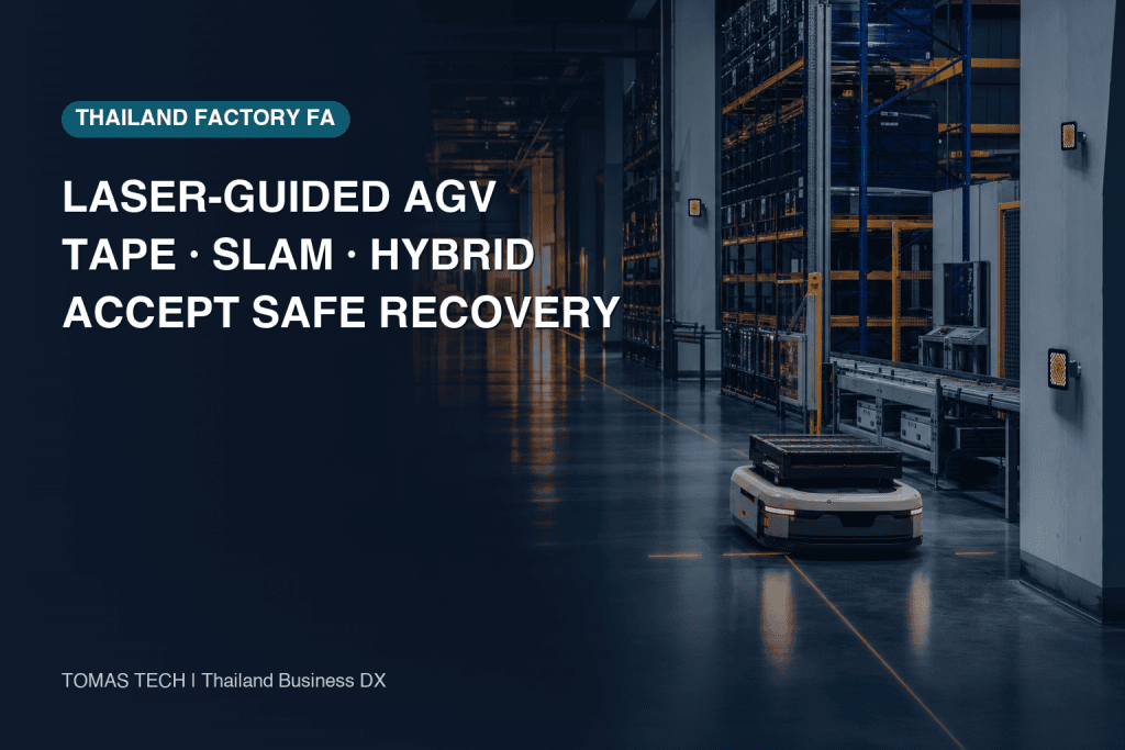
When a factory automates internal logistics, choosing “laser-guided AGV for accuracy” or “SLAM because it needs no infrastructure” is too shallow. The result depends less on the largest number in a vehicle catalogue than on how often the layout changes, what stopping tolerance the process actually needs, how dust, lighting and occlusion vary, and whether local maintenance can govern landmarks and maps. This guide turns laser-reflector guidance, magnetic tape, natural-feature SLAM and hybrid navigation into a practical process for a Thai factory—from RFP and site survey to acceptance and handover.
Select a laser-guided AGV with four operating axes
Start with change frequency × required stopping accuracy × environmental variability × maintenance capability. If any axis remains vague, a demonstration can succeed while production suffers repeated stops or long recovery.
1. Change frequency: what moves, and how often?
Do not count only annual line rearrangements. Include racks, temporary storage, fixtures, buffers, forklift waiting zones, construction screens and doors that change visibility or aisle width during normal work. A reflector may be fixed to a column yet become invisible behind stacked containers. Natural-feature SLAM also needs map governance when stable environmental features change materially.
Classify change as approved permanent change, planned temporary change or unannounced operational variation. Permanent change needs approval for maps, reflectors or tape. Temporary change needs a detour and restoration deadline. Daily variation needs defined obstacle handling and safe-stop rules.
2. Required stopping accuracy: separate sensor error from vehicle stop performance
Stopping accuracy is not the same as a localization sensor’s position error. The actual stop depends on localization, control cycle, approach speed, payload and centre of gravity, floor slope and friction, wheel wear, calibration, docking hardware and final sensors. SICK’s NAV350 instructions, for example, publish a product-specific systematic position error of ±4–25 mm depending on average reflector distance. That value must not be copied into a guarantee for a loaded AGV.
If a transfer point needs tight repeatability, separate route localization from final docking. Mechanical guides, short-range sensors or a local marker may be justified at the final approach. Specifying the actual process points, tolerance and measurement method is more economical and maintainable than demanding maximum accuracy everywhere.
3. Environmental variability: survey what is visible, reflective and dirty
Laser-reflector design depends on visibility geometry, occlusion, contamination, angle, vibration and unintended relocation. Natural-feature SLAM depends on the distribution of stable walls, columns and machines and can be affected by glass, repetitive aisles, moving racks and large doors. Magnetic tape depends on floor condition, cutting, peeling, cleaning, oil, water and route-change work. Treat these as part of the operating zone together with traffic and sensor-window contamination.
4. Maintenance capability: define who can restore what
Sophisticated navigation does not improve availability if every diagnosis waits for a vendor visit. The RFP should require interpretable logs, inspection and cleaning rules, spares, version-controlled maps and settings, change rights, restore procedures and escalation thresholds. Magnetic tape also needs governance: an unrecorded patch or shifted branch can destabilize the process.

Compare AGV navigation types by site condition
This matrix is a question generator, not a universal ranking.
| Method | Conditions that may fit | Main design objects | Work after a change | Acceptance focus |
|---|---|---|---|---|
| Laser reflectors | Stable landmarks can be installed; flexible routes and repeatability are needed | Reflector position, height, angle, visibility and occlusion | Landmark register, re-survey, map update | Missing, blocked, dirty or shifted reflector; relocalization after restart |
| Magnetic tape | Routes are stable and floor guidance should be easy to understand | Tape path, branches, stop markers and floor preparation | Floor work, replacement and route-drawing update | Peeling, discontinuity, shifted branch and post-repair check |
| Natural-feature SLAM | Stable natural features exist and site landmarks should be reduced | Map quality, feature distribution, change zones and remapping | Map comparison, approval and version control | Feature scarcity, repetitive aisles, temporary objects and rollback |
| Hybrid | Different zones have conflicting requirements | Switching rules, priority, common coordinates and fallback | Governance of multiple maps and landmarks | Transition boundary, loss of one mode and prevention of unsafe fallback |
Laser-reflector guidance: flexibility in exchange for landmark governance
A laser-reflector system observes installed reflectors and estimates position from known coordinates. It can define routes without a continuous floor line, but every reflector becomes a governed asset. The project needs an as-built drawing, identity, mounting height and angle, surrounding occlusions, inspection interval and change history.
Check visibility during turns, with maximum load, with oncoming vehicles stopped and with racks at realistic occupancy. More reflectors are not automatically better; false returns, maintenance effort and relocation exposure can also increase. Use the selected vendor’s design rules and measure visibility margin by zone.
Magnetic-tape AGV: protect simplicity with change control
Magnetic tape provides an understandable floor path and can be rational where routes remain stable and floor repair is controlled. It also makes layout change a physical task. Cleaning, heavy carts, floor cutting, oil, water, joints and repair materials must be considered.
Acceptance should include vendor-approved simulations of partial peeling, joints, branch misalignment and post-repair operation. If technicians may make a short local repair, position verification and a recorded change must still be mandatory.
SLAM AMR: less infrastructure does not mean no map management
OMRON’s LD-250 page describes, for that product, natural-feature SLAM without tape or markers and accommodation of layout changes. This is a meaningful advantage, not proof that every factory is infrastructure-free.
Long repetitive aisles, similar columns, reflective surfaces, moving racks, temporary walls and large doors can challenge feature stability. Define who may update a map, how differences are reviewed, how a release is approved and how the previous version is restored. Obstacle avoidance and map editing are different decisions: avoiding a temporary pallet must not automatically make it a permanent landmark.
Hybrid navigation: the switching specification is the real design
Kollmorgen’s CVC700 material presents product options including laser, natural and magnetic-tape navigation and multi-navigation. A hybrid architecture may use natural features in long aisles and a local landmark near a transfer point. Exact capability must be confirmed for the offered vehicle and controller.
The key is not merely having two technologies. Specify when the system switches, which source has priority and whether it slows or safely stops when confidence falls. Test coordinate consistency, position jumps at boundaries and mismatched map/reflector versions.
Design reflector placement through a site survey
A drawing alone misses production occlusion. Walk every route from the scanner’s installed height and record columns, machines, racks, doors, shutters, loads, people and forklift movement. Inspect normal operation and peak occupancy where practical.
What belongs in a reflector register
Record identifier, coordinate, mounting surface, height, orientation, installation date, photograph, visible zone, inspection interval, cleaning method and change approver. Maintenance must be able to reconcile the physical landmark with the drawing. Building work and machine-relocation requests should include a reflector-impact check.
Measure margin under adverse, not average, conditions
Check full containers, occupied upper racks, a stopped opposing vehicle, a partly open shutter and deployed work screens. If the design can continue after limited landmark loss, document the vendor-defined permitted condition. Site personnel must not relax confidence thresholds independently.
How to use product-specific figures
SICK’s NAV350 instructions publish a 0.5–70 m reflector measurement range, ±4–25 mm systematic position error depending on average reflector distance, capacity up to 12,000 reflectors and 320 layers, and class 1 laser classification. Kollmorgen’s LS2000 publishes reflector detection up to 100 m and natural-environment ranges of 0.1–10 m at 10% reflectivity and 0.1–30 m at 90%, also class 1. A Pepperl+Fuchs R2000 application describes product-specific values of up to 60 m on natural surfaces, up to 200 m on reflectors, 360° coverage and 50 Hz.
These figures demonstrate product possibilities under different conditions; they are not a like-for-like ranking. Vehicle speed, mounting, targets, reflectivity, ambient light, filtering and controller behavior differ. The RFP should state required visibility margin, localization confidence, process tolerance and test method, then require evidence for the offered product.
Engineer safety at system and operating-zone level
ISO 3691-4:2023 addresses safety requirements and verification methods for driverless industrial trucks and their systems. Its public description notes that operating-zone conditions materially affect safe operation. High sensor accuracy, a class 1 laser or obstacle detection alone therefore cannot establish safety for the installation.
The ISO Online Browsing Platform also shows an ISO/DIS 3691-4 edition 3 revision under development. It must be distinguished from the published 2023 edition. Applicable legal, contractual and standards requirements should be confirmed for the country, machine configuration and customer requirement at procurement time.
Include every interface in the operating zone
Cover routes, intersections, pedestrian crossings, doors, elevators, conveyor transfers, charging, parking, manual operation, maintenance areas, escape routes and shared forklift space. Elevator integration adds door, car-arrival, load, communications, rescue and emergency boundaries. See our detailed guide to AGV–elevator integration in Thai factories.
Define the state after localization degradation
Risk assessment and system design determine whether reduced localization confidence leads to reduced speed, controlled stop or a safety-related stop. “Stop when lost” is incomplete: define fleet reaction, load ownership, safe approach by personnel, manual authority and checks before relocalization and restart.
Accept degraded operation and documented recovery—not only normal travel
A clean demonstration aisle with stable wireless coverage hides production failure modes. Site acceptance should inject realistic degradation under an approved risk assessment, procedure, exclusion zone, stop method and recovery responsibility.

Missing, blocked or shifted reflectors
Under vendor-approved conditions, temporarily obscure a permitted landmark on a representative route and observe confidence, alarm, speed/stop behavior, event log and fleet display. The aim is not to search for a dangerous failure limit. Restore the landmark, verify its physical position and map version, and require authorized restart rather than uncontrolled automatic resumption.
Lighting, dust, contamination and reflectivity
Test realistic conditions before and after routine cleaning, day/night changes, doors, nearby equipment light and reflective surroundings. Do not damage a sensor with arbitrary dust. Use expected site conditions and manufacturer limits to verify dirty-window diagnostics, cleaning alarms and maintenance intervals.
Communications loss and inconsistent upstream state
Test wireless LAN, fleet manager, MES/WMS, PLC, doors and elevators as separate boundaries. After reconnection, verify that an old transport order is not executed twice, equipment state is refreshed and ownership of work in progress is unique. Healthy navigation does not authorize movement when upstream state is unknown.
Obstacles and blocked aisles
Use approved test objects representing people, carts and pallets to verify detection, deceleration, stopping, rerouting and timeout. Confirm that the vehicle stops rather than detours in zones where bypass is prohibited. Test order cancellation, redispatch and controlled switch to manual logistics during prolonged blockage.
Restart, power restoration and manual intervention
Test restart order for the vehicle, fleet manager, access points and upstream equipment. Automatic recovery must wait until position, load, mission and interface states agree. Manual intervention needs defined authorization, speed, movement boundary, load handling and pre-auto checklist.
Make recovery evidence a deliverable
Save test ID, preconditions, software/map/configuration versions, measurements, synchronized logs, alarms, stop state, recovery actions, approver and open issues. Video is helpful but does not replace searchable records. Acceptance should demonstrate that local maintenance can reproduce diagnosis and recovery.
Manage six gates from RFP to handover
Do not end selection with one quotation comparison. Define evidence required to advance and return the design when evidence is missing.

Gate 1 — RFP: define outcome and boundaries
Specify transport demand, path, process stopping tolerance, takt, load, operating hours, shared zones, change frequency, environment, upstream interfaces and manual fallback. If a navigation mode is prescribed, state why and under what conditions alternatives are acceptable.
Gate 2 — Site survey: replace assumptions with measurements
Measure drawing dimensions, floor, slope, aisle width, reflector surfaces, natural features, tape surface, wireless coverage, lighting, dust and traffic. Preserve photographs and coordinates, and identify unmeasured zones. Observe operating production where feasible.
Gate 3 — Pilot: test the hardest zone
Choose occlusion, crossing, transfer, wireless boundary or frequent-change risk—not an easy straight aisle. The pilot should discover assumptions and limits, then update the RFP and operating plan.
Gate 4 — FAT: verify configuration and failure response
At factory acceptance, confirm vehicle configuration, software version, simulated interfaces, alarms, permissions, backups and representative faults. Explicitly transfer site-only tests to SAT with reasons.
Gate 5 — SAT: accept the real operating zone
Use the actual floor, reflectors, map, tape, network, equipment and traffic. Verify normal performance, stop repeatability, protective functions, fault injection, recovery, endurance and maintenance. Any conditional acceptance needs a permanent action, due date, owner and operating restriction.
Gate 6 — Handover: prove maintainability
Deliver as-built drawings, reflector register, map/configuration/software versions, backups, restore instructions, maintenance criteria, spares, training records, access matrix, support contacts and open-issue register. Operators, maintenance, IT/OT, facilities, safety and process owners should demonstrate their roles.
Laser-guided AGV RFP checklist
| Area | Question for the bidder | Acceptance evidence |
|---|---|---|
| Transport | What load, mass, centre of gravity, transfer, takt and peak apply? | Travel and transfer record with representative load |
| Navigation | What mode, switching rule, landmarks and low-confidence behavior apply? | Design, map, landmark register and fault logs |
| Stop | What tolerance and measurement method applies at each process? | Repeated measurements with load, speed and floor recorded |
| Environment | What lighting, dust, reflection, floor and occlusion limits apply? | Survey and adverse-condition test |
| Safety | What operating zone, traffic and protective measures apply? | Risk assessment, verification record and residual-risk briefing |
| Interfaces | What WMS/MES/PLC/door/elevator state machines apply? | Loss, duplicate-prevention and recovery test |
| Maintenance | Who inspects, calibrates, cleans, holds spares and changes maps? | Procedures, training, demonstration and access rights |
| Cybersecurity | How are accounts, updates, remote access, logs and backups governed? | Access matrix, update/restore test and log-retention check |
| Handover | What formats, versions, languages and support boundaries are delivered? | Deliverable register, receipt and open-issue list |
Do not reduce AGV selection to purchase price
Navigation affects installation, change work, cleaning, calibration, map governance, recovery, training, spares and vendor dependence. Compare all options over the same operating period and conditions. Our five-year AGV and AMR TCO guide for Thailand provides a structured cost framework.
Reflector systems incur mounting, survey and inspection work; tape involves floor installation and repair; SLAM needs map and environment governance; hybrid systems need multi-mode validation and skills. Estimate work per change, planned downtime, internal capability and external support rather than declaring one method inherently expensive or cheap.
Confirm the boundary of Thailand BOI measures
Thailand BOI’s Thai-language automation page describes a measure under Announcement 4/2569 for applications from the first working day of 2026 through the last working day of 2027, limited to the covered automotive categories. The minimum investment is THB 1 million, excluding land and working capital. The three-year corporate-income-tax exemption is capped at 50% of qualifying automation and robotics investment. The cap becomes 100% when machinery that supports Thailand’s domestic automation-machinery industry represents at least 30% of the value of the machinery being modified or of total machinery value. This is not automatic eligibility for every AGV project. Confirm industry coverage, qualifying investment, the domestic-industry linkage test, timing and individual approval with BOI and competent tax/legal advisers.
Select a safe, operable architecture first, then assess eligibility separately. These figures describe published conditions and do not promise approval or a tax outcome.
Frequently asked questions
What is a laser-guided AGV?
It generally observes known landmarks such as reflectors with a laser scanner and estimates its position. Products differ in natural-feature combination, map structure, reflector requirements and failure response. Verify the offered product’s manuals and site design.
Is magnetic tape or laser guidance better for an AGV?
Neither is universally better. Tape may fit a stable route with controlled floor work. Laser may fit flexible routing where stable reflectors can be governed. Compare change frequency, process tolerance, floor/wall environment and maintenance capability.
Does a SLAM AMR need no reflectors or magnetic tape?
Some natural-feature SLAM products operate without tape or markers, but still require stable features, a governed map and relocalization tests. A local marker or mechanical guide may still be used for a demanding final dock.
How are AGV types classified?
Besides navigation, AGVs differ by load handling—under-ride, towing, conveyor or fork—payload, operating environment, protective functions and fleet architecture. Load handling and process interfaces should be defined before selecting a vehicle.
How should stopping accuracy be specified?
For each process point, define datum, direction, tolerance, load, approach speed, floor condition, instrument, repetition and acceptance logic. Measure the complete vehicle at the real process. Review maximum deviation and fault behavior, not only averages.
How many reflectors are required?
There is no reliable generic count. It depends on scanner, field of view, route, height, occlusion, required confidence and vendor algorithm. Design it through a site survey and verify margin under adverse conditions.
Does class 1 laser classification remove the need for safety acceptance?
No. It classifies the relevant laser product; it does not accept vehicle travel, stopping, obstacle detection, load handling, traffic or the operating zone. Validate system safety under the project’s risk assessment and applicable requirements.
What must be retested after a layout change?
Based on impact, retest maps, reflectors or tape, visibility, stopping, intersections, wireless coverage, equipment interfaces, protective functions and fault recovery. Preserve the prior version and record approval, implementation, verification and release.
May the system restart automatically after a communications outage?
Only if the approved state machine can verify position, load, mission and equipment state consistently and prevent duplicate action. Otherwise stop safely and require authorized confirmation.
Conclusion: select the AGV by acceptance evidence, not the method name
Laser reflectors, magnetic tape, SLAM and hybrid navigation each fit different conditions. The decision axes are change frequency, required stopping accuracy, environmental variability and maintenance capability. Product sensor values are not complete-vehicle guarantees; measure the offered system in the operating zone.
Acceptance must go beyond normal travel. Test approved reflector loss or occlusion, realistic lighting and contamination, communications loss, obstacles, restart and manual intervention, preserving evidence from stop through recovery. Evidence gates at RFP, site survey, pilot, FAT, SAT and handover reduce production downtime and dependence on individual experts.
TOMAS TECH supports Thai factories with transport requirements, navigation comparisons, site surveys for landmarks/maps/interfaces and FAT/SAT test design. You can contact us while the vehicle and navigation mode are still undecided; we can begin by turning site conditions into an auditable RFP.


