


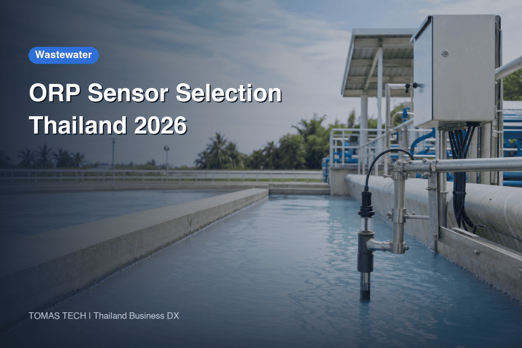
Selecting and Operating ORP Sensors for Industrial Wastewater Treatment: A Practical Guide for Manufacturing Plants in Thailand
In Thailand’s manufacturing sector, the selection and operation of ORP (Oxidation-Reduction Potential) sensors for factory wastewater treatment is a highly practical challenge. Especially in facilities handling various chemicals and metals, it is essential to go beyond simple pH or BOD/COD measurements to understand process behavior, optimize chemical dosing, and enable rapid anomaly detection. This article, tailored for Thai factory wastewater treatment contexts, provides a detailed, step-by-step guide—from choosing installation points and utilizing data, to maintenance, procurement, FAT/SAT, and common pitfalls—covering all the practical considerations for on-site implementation.
What ORP Can and Cannot Tell You: Comparison with pH and BOD/COD, and the Difference Between ORP, Eh, and Reference Electrodes
ORP (Oxidation-Reduction Potential) is a process indicator that reflects the tendency of oxidation and reduction reactions in wastewater. It is primarily used for process control, anomaly detection, and determining optimal chemical dosing timing. However, unlike pH or BOD/COD, ORP does not directly indicate specific substance concentrations or legal compliance.
Comparison Table: ORP, pH, and BOD/COD
| Indicator | Meaning & Application | Measurement Method | Advantages | Limitations & Caveats |
|---|---|---|---|---|
| ORP | Indicator of redox reactions. Used for process control and anomaly detection | Electrode-based | Continuous monitoring, immediate response | Cannot identify specific substances, depends on reference electrode and temperature |
| pH | Indicator of hydrogen ion concentration. Used for neutralization and corrosion management | Electrode-based | Continuous monitoring, closely tied to legal standards | Highly affected by buffers and mixing |
| BOD/COD | Indicator of organic load. Used to check applicable discharge conditions | Specified analytical method | Compare results with applicable permit or contract conditions | Cannot be measured quickly, difficult for continuous monitoring |
ORP values vary depending on the type of reference electrode (e.g., Eh—Standard Hydrogen Electrode, Ag/AgCl) and temperature. Therefore, absolute mV values or thresholds cannot be directly compared across different sites or literature sources. ORP is best used for “trend monitoring” to observe relative changes in process conditions or chemical dosing at your specific site.
Additionally, BOD and COD indicate the organic load in wastewater, and parameters required by an applicable permit or contract must be checked using the specified sampling and analytical methods. ORP does not directly correlate to these values and should be considered a supplementary indicator for process management and anomaly detection.
Mapping the Wastewater Path and Selecting Measurement Points: Ensuring Representativeness, Installation Depth, Mixing, and Avoiding Dead Zones
In Thai factory wastewater treatment, there are often multiple process effluents and chemical dosing points, making the selection of ORP sensor installation locations critical. Below are typical candidate points for measurement and specific considerations for installation.
Typical Measurement Candidate Points
- Equalization Basin
– Temporarily collects wastewater from various processes, evening out fluctuations and providing high representativeness.
– If mixing is insufficient, dead zones (areas of stagnant flow) or surface bubbles/scum can affect readings.
– Follow manufacturer’s recommended immersion depth (for the actual liquid-level range and manufacturer’s specified immersion conditions); avoid installing near agitators or immediately after inflow.
- Before and After Chemical Dosing (Oxidant/Reductant Injection Points)
– Ideally, measure both immediately after dosing and after the reaction to assess chemical effectiveness and reaction progress.
– Avoid locations where reactions are incomplete or flow is extremely slow; ensure representative mixing.
– For in-pipe installations, consider flow rate, pressure, and whether a bypass line is available.
- Final Discharge Point
– Just before releasing treated wastewater into public sewers or industrial estate drainage.
– ORP values here reflect the cumulative result of all processes and may miss localized anomalies or over/under-dosing.
– Ensure sampling valves and maintenance access are available.
Key Considerations for Installation
- Avoid Dead Zones: Do not install in areas with stagnant flow or where scum and floating debris accumulate.
- Aeration Effects: In aeration tanks, bubbles and oxygen injection can disrupt ORP readings—avoid just below aerators or near the surface.
- Ensure Representativeness: For multiple inflows, select a well-mixed point. Consider installing near agitators or in bypass lines if needed.
- Immersion Depth: Check manufacturer guidelines; check minimum liquid level and sludge height so the electrode remains submerged without entering deposits.
- Maintainability: Ensure access for regular inspection and calibration, with walkways or lifting mechanisms as needed.
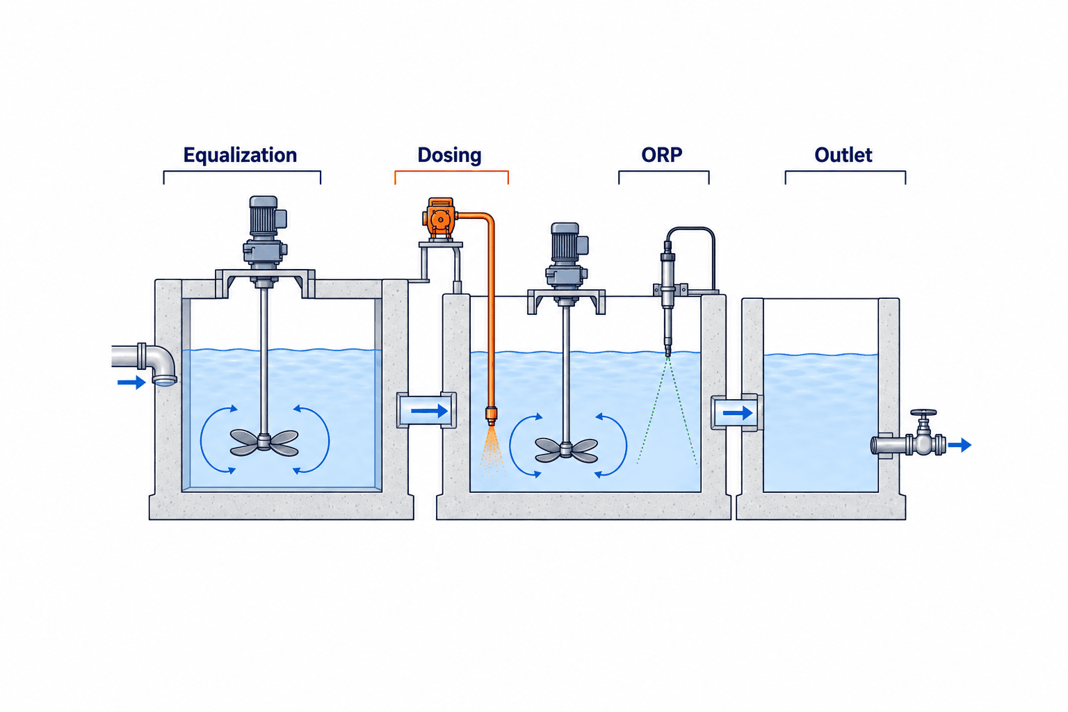
Example Design Case: Metal Surface Treatment Plant in Thailand (Fictional Scenario)—From Site Survey to Measurement Points and Operational Flow
Here, we present a fictional example based on a Thai metal surface treatment plant. The numbers and legal standards are illustrative; focus is on procedure and workflow.
Plant Overview (Sample)
- Main Processes: Pickling, plating, rinsing, waste treatment
- Wastewater Inflows: Pickling process effluent, plating process effluent, rinse water
- Treatment Flow: Equalization basin → Neutralization tank → Redox treatment tank → Sedimentation tank → Discharge
Baseline Survey Procedure (Example)
- Site Interviews and P&ID Review
– Confirm effluent volumes, chemical dosing points, and existing instrumentation for each process.
- Representative Sampling and Lab Analysis
– Collect samples from each process, the equalization basin, and final discharge.
– Analyze for ORP, pH, BOD, COD, metal ions, etc. (use the sampling and analysis methods required by the applicable permit or contract).
- Temporary ORP Sensor Installation and Continuous Measurement
– Temporarily install ORP sensors at three points: equalization basin, neutralization tank outlet, and redox treatment tank outlet; collect continuous data for one week.
– Assess representativeness, variability, and response to chemical dosing.
- Data Evaluation and Finalizing Measurement Points
– Use temporary data to select the most effective points for process control and anomaly detection.
– Consider maintainability and safety.
- Permanent Installation and Operational Flow Development
– Install permanent ORP sensors, integrate with PLC/SCADA, set alarms, and prepare calibration and inspection procedures.
Sample Operational Flow
- Normal Operation: Continuously monitor ORP and compare with sample results. Enable automatic dosing only after site validation and verification of independent safety interlocks.
- Abnormal Events: If ORP changes rapidly or goes outside set range, conduct on-site inspection, sampling, and adjust chemical dosing.
- Regular Maintenance: During the trial, record fouling and standard-solution check results, then set a site-specific cleaning and inspection interval.
*Note: This is a sample only. Actual design and operation must be customized to site conditions, legal requirements, and wastewater characteristics.*
ORP Sensor, Transmitter, and Assembly Selection Matrix
Selecting an ORP sensor requires a multi-faceted evaluation—electrode material, reference electrode type, anti-fouling features, cable/digital interface, installation method, maintainability, spare parts supply, and local service support. Use the matrix below to choose the optimal model for your site requirements.
ORP Sensor Selection Matrix
| Item | Main Options/Specifications | Selection Points & Notes |
|---|---|---|
| Electrode Material | Platinum (Pt), Gold (Au) | Compare the site water matrix with vendor compatibility guidance and verify response in actual liquid and standards |
| Reference Electrode | Ag/AgCl or the selected model’s stated reference | Choose based on site temperature, chemicals, and maintenance needs |
| Junction Structure | Ceramic, porous, double junction | For sludge, oil, or high-concentration chemicals, select clog-resistant designs |
| Anti-Fouling Features | Automatic cleaning, special coatings | For dirty sites, prioritize auto-cleaning or anti-fouling models |
| Cable/Digital Interface | Sensor-to-transmitter: Memosens, etc.; transmitter-to-PLC: 4-20mA, HART, Modbus, Profibus, etc. | Ensure compatibility with existing PLC/SCADA, wiring distance, digital readiness |
| Installation Method | Immersion, flow cell, retractable | Choose based on maintenance frequency and available space |
| Temperature/Pressure | Check the candidate datasheet | Cover minimum/maximum site temperature and maximum pressure |
| Chemical/Corrosion Resistance | PVDF, PEEK, PP, SUS, etc. | Confirm wetted materials withstand site chemicals and pH fluctuations |
| Cleaning/Calibration Mechanism | Auto-cleaning nozzle, retractable/exchangeable | Ease of manual cleaning/calibration, availability of replacement parts |
| Spare Parts/Consumables | Electrodes, O-rings, cleaning solutions, etc. | Check lead time, price, and local stock for regular replacements |
| Local Service Support | Direct manufacturer, agent, local technician | Confirm support and emergency response within Thailand |
| mV Display/Reference Electrode Indication | Ag/AgCl reference, Eh conversion | Always check specifications for reference electrode and temperature conditions |
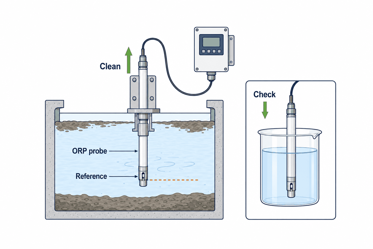
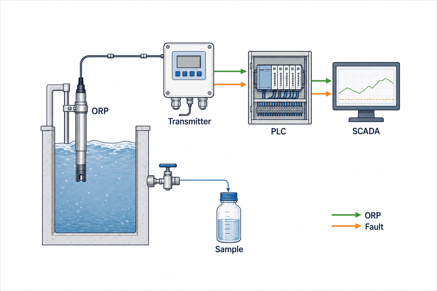
Electrical and Data Architecture: Sensor → Transmitter → PLC/SCADA/Historian
Signals from the ORP sensor are converted by a transmitter and sent to the plant’s PLC, SCADA, or historian (data logger). Be sure to confirm and design for the following points:
Signal Transmission and Data Structure
- Analog Transmission: 4-20mA signals are standard and highly compatible with existing control panels and PLC input cards.
- Separate the links: Memosens is a digital connection between compatible sensors and transmitters. For the transmitter-to-PLC link, select a supported output such as HART, Modbus, or Profibus. Confirm that the chosen transmitter and configuration expose calibration history and diagnostics to the upper-level system.
- Timestamps and Quality Flags: All data should include time information, sensor status (calibration, cleaning, fault, etc.), and quality flags (warnings for reduced reliability).
- Cross-Check with Manual Samples: Align sample timestamps and assess ORP trends alongside relevant lab analyte trends; do not directly equate unlike units. Check electrode drift separately with an ORP standard or reference instrument.
Managing Data Gaps and Maintenance States
- During Maintenance: Automatically flag data as “under maintenance” during cleaning, calibration, or replacement to prevent missing data or false alarms.
- Data Gaps: In case of communication loss or sensor failure, clearly record and alert “data missing” in SCADA/historian systems.
Cleaning, Inspection, and Calibration of ORP Sensors: Importance of Standard Solutions, Stabilization, Reference Electrodes, Temperature, and Manufacturer Procedures
ORP sensor maintenance varies greatly depending on wastewater characteristics and installation environment. Below are general procedures and points for cleaning, inspection, and calibration.
Basics of Cleaning, Inspection, and Calibration
- Cleaning: Remove deposits, scale, oils, etc. Use manufacturer-recommended cleaning solutions and brushes; avoid damaging electrodes.
- Inspection: Check for damage to exterior, cables, connectors, O-rings, etc. Inspect reference electrode for leakage or clogging.
- Calibration (Check): Immerse in standard ORP solution (e.g., Zobell solution) and confirm that readings are within the manufacturer’s specified tolerance. Allow several minutes for stabilization.
- Adjustment: If deviation in calibration solution exceeds tolerance, adjust offset in transmitter or consider electrode replacement.
Setting Calibration and Inspection Frequency
- No universal recommended interval. Set optimal inspection/calibration intervals based on site fouling, chemical load, process variability, and initial operation data.
- During commissioning, accumulate data and inspection records over 1 week to 1 month to determine the best frequency for your site.
Safety and Chemical Handling
- Always wear appropriate protective gear during cleaning and calibration. Handle and dispose of chemicals according to site rules and legal requirements.
Alarm Design: Baseline and Lab Value Correlation, Duration and Quality Judgement, Distinguishing Instrumentation from Process Faults, Actions and Escalation
Alarm design for ORP sensors goes beyond simple threshold settings. It requires correlation with site baselines and lab analysis, distinguishing between instrumentation and process faults, and clear action/escalation protocols.
Key Points for Alarm Design
- Baseline Setting: During initial commissioning, record normal ORP fluctuation ranges and responses to chemical dosing to define site-specific “normal ranges.”
- Cross-Check with Lab Values: Pair time-stamped ORP trends with laboratory results for relevant analytes to assess process association; do not compare unlike units as if they were equal. Check electrode drift separately against an ORP standard or reference instrument.
- Duration and Quality Flags: To prevent false alarms from transient noise or during cleaning, implement gating based on minimum duration and quality flags.
- Distinguishing Instrumentation vs. Process Faults: Use “instrumentation fault” alarms for sensor disconnection, calibration errors, or maintenance; use “process fault” alarms for process value deviations, and define separate responses.
- Independent Verification and Escalation: On alarm, clarify actions such as on-site inspection, sampling, and chemical adjustment. For major anomalies, automatically escalate to senior management.
Example Alarm Response Flow Table
| Alarm Type | Example Detection Condition | Example Response Action | Escalation |
|---|---|---|---|
| Process Fault | ORP value outside normal range | On-site check, sampling, chemical adjustment | Notify manager |
| Sustained Fault | Deviation persists for a site-validated period | Detailed inspection, request lab analysis | Notify senior management |
| Instrumentation Fault | Sensor disconnection, calibration, etc. | Switch to backup sensor, on-site inspection | Notify instrumentation staff |
| Quality Degradation | Quality flag ON | Clean, calibrate, replace parts | Notify instrumentation staff |
*Note: ORP values alone cannot guarantee compliance with wastewater standards. For parameters required by the site permit or contract, also use the specified sampling and analytical methods.*
RFP Checklist: 14 Procurement Points + Lifecycle Cost Comparison
When procuring ORP sensors, evaluate not only initial price but also installation/maintenance, spare parts, local support, warranty, and operational costs. Use the checklist below for RFPs (Requests for Proposal) and vendor comparisons.
RFP Checklist (Sample)
- Electrode material and reference electrode clearly specified (Pt/Au, Ag/AgCl, etc.)
- Chemical compatibility of wetted materials (PVDF, PEEK, PP, SUS, etc.)
- Installation method (immersion/flow cell/retractable) and dimension drawings
- Transmitter output (4-20mA, digital interface, etc.) and PLC/SCADA compatibility
- Maximum/minimum specifications for temperature, pressure, pH, and chemical resistance
- Presence and details of automatic cleaning/calibration mechanisms
- Lead time, price, and local stock for spare parts/consumables (electrodes, O-rings, etc.)
- Local service and technical support structure (Thailand office, response hours)
- Warranty period and coverage (parts, labor, on-site support, etc.)
- Availability of calibration/inspection/replacement manuals (Thai/English/Japanese)
- On-site installation, commissioning, and training support
- Clear indication of mV display reference electrode and temperature conditions
- Delivery record and reference user list (same industry, within Thailand)
- Lifecycle cost breakdown (initial, operational, consumables, maintenance contracts, disposal, etc.)
Lifecycle Cost Comparison Categories (Sample)
- Initial Costs: Main unit, transmitter, installation work, initial calibration
- Operational/Maintenance Costs: Cleaning, calibration, inspection, consumables, spare parts
- Failure/Replacement Costs: Electrode, reference electrode, cable replacement
- Local Support Costs: Emergency response, technical support, training
- Disposal/Upgrade Costs: End-of-life disposal, new equipment introduction
FAT/SAT (Factory and Site Acceptance Test): Pass/Fail Criteria and Procedures
When introducing ORP sensors, conduct FAT (Factory Acceptance Test) at the manufacturer and SAT (Site Acceptance Test) after on-site installation to verify performance, signal transmission, data recording, and maintainability as per specifications. Pass/fail criteria (e.g., allowable error) must be agreed in advance based on manufacturer specs and site process requirements.
Main FAT (Factory Acceptance Test) Items
- Check appearance, dimensions, model numbers, and accessories
- Calibration and response test using standard ORP solution
- Transmitter output (4-20mA, etc.): scaling, zero/span check
- Digital communication (HART/Modbus, etc.): protocol and data item check
- Simulated tests for sensor disconnection, short circuit, abnormal signals
Main SAT (Site Acceptance Test) Items
- Check installation, wiring, grounding, and waterproofing
- Verify response and stability in actual site liquid (cross-check with representative samples)
- Confirm transmitter output, data recording to PLC/SCADA/historian, timestamp, and quality flags
- Test alarm triggering, maintenance flags, and data gap handling
- On-site training and handover for maintenance, cleaning, and calibration procedures
Pass/Fail Points
- Allowable error, response time, and signal scaling must be agreed in advance per manufacturer specs and site needs
- Cross-check site ORP against a reference ORP instrument and separately assess its time-series relationship with relevant laboratory analytes; unlike measurements need not numerically match
- Alarms and data gaps for transmitter faults/disconnection must be correctly recorded
Common Failure Patterns, 90-Day Commissioning Sequence, and FAQ
Common Failure Patterns
- Lack of Representativeness in Installation Location: Installing in dead zones or areas with bubbles/debris leads to unrepresentative data.
- Failure to Confirm Reference Electrode and Temperature Conditions: Carelessly comparing absolute mV values with other companies/sites leads to incorrect operation or alarm settings.
- Insufficient Maintenance/Calibration Frequency: Underestimating site fouling or chemical load causes sensor drift or undetected failures.
- Poor Data Quality/Alarm Design: False alarms during maintenance or due to transient noise, causing on-site confusion.
- Lack of Spare Parts/Local Support: Extended downtime or high emergency shipping costs during failures.
90-Day Commissioning Sequence (Example)
- Installation, wiring, and initial power-up
- Initial cleaning, inspection, and calibration with standard solution
- One week of continuous data collection and representativeness assessment
- Cross-check with lab analysis, provisional alarm threshold setting
- One month of inspection, cleaning, and calibration record accumulation
- Finalize optimal inspection/calibration frequency and document procedures
- On-site training and maintenance handover
- Comprehensive review and operational improvement proposal after three months
FAQ (Frequently Asked Questions)
Q1. Why does the ORP value differ from pH or BOD/COD?
A1. ORP indicates the “trend” of redox reactions in water and does not directly show concentrations of specific substances or legal standard values. pH and BOD/COD respectively indicate hydrogen ion concentration and organic load, so their uses and interpretations differ.
Q2. How often should ORP sensors be calibrated?
A2. There is no universal recommended interval. Set the optimal frequency based on site fouling, chemical load, and initial operational data. Start with frequent checks, record fouling and standard-solution results, and extend the interval only when the evidence supports it.
Q3. How should I set ORP alarm thresholds?
A3. Use site baseline data and correlation with lab analysis to set ranges that reliably detect process anomalies. Design not just by absolute values, but also by trends, duration, and quality flags.
Q4. Can ORP sensors alone determine compliance with wastewater standards?
A4. No. ORP is a supplementary indicator for process management and anomaly detection; legal compliance always requires lab or official analysis.
Q5. How can I ensure local support and spare parts supply in Thailand?
A5. When selecting vendors, always confirm the presence of local service centers/technicians and spare parts stock in Thailand, and specify this in your RFP or contract.
Consulting with TOMAS TECH: Please Prepare P&ID, Water Flow Sketches, Water Quality Test Results, and Discharge Permit Conditions
For selecting and implementing ORP sensors in factory wastewater, preparing your site’s P&ID (piping and instrumentation diagram), water flow sketches, historical water quality test results, and relevant industrial estate or government discharge permit conditions (applicable clauses) will enable us to provide more concrete proposals.
Please also refer to Factory Wastewater Monitoring Design and Industrial pH Sensor Selection for Factories.
Contact TOMAS TECH to discuss measurement points, instrumentation and data connections, and operating procedures. Confirm permit obligations and required analyses with the plant team and an appropriate laboratory.
References and Source List
- https://www.epa.gov/quality/field-measurement-oxidation-reduction-potential
- https://pubs.usgs.gov/twri/twri9a6/twri9a65/twri9a_6.5_v_1.2.pdf
- https://www.ysi.com/ysi-blog/water-blogged-blog/2015/11/measuring-orp-top-tips-for-the-best-data
- https://www.yokogawa.com/library/resources/white-papers/basics-of-orp/
- https://www.us.endress.com/en/field-instruments-overview/liquid-analysis-product-overview/ORP-digital-sensor-CPS12E
- https://bdih-download.endress.com/file/a6ef81cad1df2a427eb9b0a03ae3afed/BA01988CEN_0526-00.pdf
- https://www.ysi.com/sensolyt
- https://www.epa.gov/sites/default/files/2019-08/documents/nutrient_control_design_manual.pdf
*The above URLs provide primary information on ORP measurement fundamentals, field operation, sensor specifications, and design manuals.
The process design, operational flow examples, and FAQ in this article are based on these sources and standard engineering workflows.
For detailed legal or site-specific requirements, always consult the latest primary information and local experts.*


