


When selecting factory pH sensors, it is not enough to compare only the measurement range listed in catalogs. You must specify the appropriate glass membrane and reference junction for the actual process liquid, the sampling or immersion location, cleaning and calibration procedures, abnormal signal handling, and acceptance testing—all as a single measurement point. This article organizes pre-order confirmation points for those responsible for new installations or upgrades of pH measurement in production, cleaning, or wastewater treatment processes at factories in Thailand. For an overview of discharge standards and the regulatory framework for BOD/COD, see Factory Wastewater Monitoring Explained. Here, we focus on the question: “Can you trust and use that pH value?”
Conclusion for Factory pH Sensor Selection: Start with a Measurement Point Specification
The first thing to create during procurement is not a model number list, but a specification sheet for each measurement point. Even within the same factory, relatively clean recovered water, oily wash wastewater, neutralization tanks with high suspended solids, and hot CIP return liquids all present different electrode degradation, fouling, and operator access conditions. Manufacturer application tables help narrow down candidates, but cannot replace actual response and maintainability in your process.
Each line of the specification should include the measurement purpose, liquid composition and variability, measurement location, temperature and pressure, cleaning method, required signals, calibration and replacement responsibility, and acceptance criteria. Whether the value is for display, chemical dosing control, or quality record attachment will affect the required quality flags and fail-safe behavior. If used for control, coordinate interlocks and sensor failure fallback as discussed in Water & Wastewater PLC/SCADA Design before proceeding.
| Item to Decide | What to Check Onsite | Evidence to Include in Specification |
|---|---|---|
| Purpose | Monitoring, alarm, chemical dosing control, quality/environmental record | User department and decision/operator responsibility |
| Liquid Properties | Acid/alkali, salts, oil, solids, solvents, detergents, variability | Actual liquid sample and operating conditions at sampling |
| Installation | Tank, open channel, pipeline, bypass, sample tank | P&ID, liquid level, flow, allowable downtime |
| Maintenance | Cleaning, calibration, replacement, spares, waste disposal | Safe extraction procedure and responsible personnel |
| Data | Value, temperature, quality, calibration status, timestamp | Tag list, test records, storage location |
If you leave this table blank and specify only “pH 0–14 compatible,” you cannot compare quotes from multiple vendors. Conversely, if you disclose the medium and work conditions, you can request proposals from manufacturers combining glass, junction, holder, and transmitter. Do not simply copy generic tolerances; determine required accuracy and measurement point uncertainty based on process needs.
Separate Measurement Purposes: Display Value and Control Value Have Different Requirements
Although pH appears as a single number, its use for display, anomaly detection, closed-loop control, or test report entry requires different handling. For monitoring only, it may be acceptable to indicate “maintenance in progress” and leave data gaps during cleaning or calibration. For chemical dosing control, you must define interlocks to prevent dosing during cleaning, alternative actions during faults, and conditions for resuming operation. For record-keeping, it is important to be able to trace who calibrated with which standard solution and when.
For example, using a single probe in a neutralization tank to simultaneously feed measurement values to a display, chemical dosing, and history may seem efficient. However, if that probe becomes fouled, is removed, loses communication, or calibration is delayed, all three uses are affected at once. Prepare independent verification points or portable measurement procedures, or define operational stop conditions. The need for additional sensors should be based on the impact of failures and operator response time.
When linking to quality assurance or environmental reporting, note that online pH readings may not always be legally admissible as evidence. Confirm sampling, test methods, calibration, record conditions, and regulatory approvals with the responsible parties. This article does not specify Thailand’s uniform discharge limits or measurement obligations, but addresses design decisions for the measurement chain.
Understanding pH Electrode Structure from a Procurement Perspective
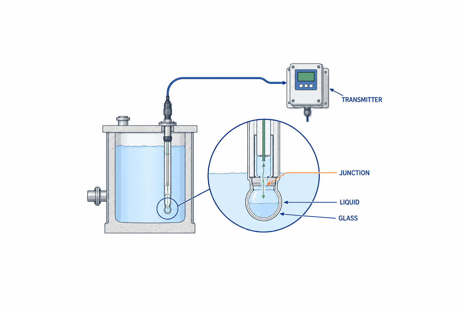
Typical process pH measurement reads the potential difference between a glass sensing element and a reference electrode via a transmitter. The reference system is electrically connected to the process liquid through the reference junction; even if the glass is robust, a clogged junction will destabilize the measurement point. Yokogawa’s selection materials highlight glass properties, reference electrode, temperature, and pressure as selection factors. Endress+Hauser’s selection guide also explains that the type of junction and reference system affects resistance to clogging and contamination.
Do not compare lifetime or accuracy based solely on terms like “combination electrode” or “digital electrode.” “Combination” usually means the measurement and reference are integrated; “digital” refers to signal transmission or calibration data handling. Resistance to fouling is a separate design factor. For example, Endress+Hauser’s Memosens CPS11E features non-contact transmission, calibration data storage, and lab calibration, but not all pH electrodes have these features.
Ultimately, evaluate the electrode, holder, cable, transmitter, and cleaning mechanism as a set. Even with sufficient flow at the site, if the electrode tip is hidden deep in a protection tube, liquid exchange may be slow. If mechanical and instrumentation design are approved separately, catalog compatibility may not guarantee stable field operation.
Selecting the Glass Membrane: Consider Liquid and Temperature, Not Just pH Range
When choosing a glass electrode, specify normal pH, pH during startup/cleaning/abnormal conditions, temperature, and chemical composition separately. For example, even if the normal liquid is near neutral, strong alkali or acid may flow during CIP; normal-only specs are insufficient. Conversely, if the electrode is retracted during cleaning, you can consider whether a costly configuration for continuous exposure to cleaning chemicals is necessary. The key is which process steps the electrode actually contacts the liquid.
Yokogawa warns of sodium error under high-alkali conditions and glass aging. Therefore, do not interpret a “0–14” measurement range as guaranteeing the same accuracy for all temperatures and media. Cross-check each candidate’s material, operating temperature, pressure, chemical resistance, and recommended applications, and confirm boundary conditions with the manufacturer in writing. If fluoride, solvents, or abrasive solids are present, provide actual liquid information including concentration and exposure time for suitability assessment.
Where glass electrodes are unsuitable, non-glass types such as ISFET may be considered. Endress+Hauser’s guide distinguishes between glass and ISFET structures and applications. However, replacing solely for “break resistance” overlooks reference system, media compatibility, cleaning, calibration, and transmitter compatibility. In comparison tables, list measurement principles and field risks, specifying which failures are reduced and which new operational requirements arise.
Is a Wider Measurement Range Always Better for Factory pH Sensors?
Not necessarily. Consider the normal and abnormal range, temperature and composition, required accuracy, response time, and fouling together. The maximum value on a product page is a conditional value for that model or option. In RFPs, specify “normal,” “cleaning,” and “abnormal” conditions, and clarify whether measurement continues or the sensor is retracted/protected in each case.
Identify Media That Will Clog the Reference Junction First
The reference junction is the contact point between the reference system and the measured liquid. Oils, fibers, pigments, slurries, precipitates, and crystalline components can foul not only the membrane but also the junction. Symptoms such as slow drift, rapid calibration drift, or slow response after calibration may indicate reference system issues. Yokogawa emphasizes junction selection, and Endress+Hauser’s guide lists ceramic, PTFE, open, and other types by medium.
Do not lump all “fouling liquids” together; classify what adheres. Oil films relate to cleaning agents and procedures, solids to flow and adhesion points, crystal precipitation to temperature changes and stagnation during shutdown, and chemical effects on the reference system to material and refill method. Use application tables for candidate extraction, and record fouling and cleaning time with actual liquid. Provide manufacturers with samples not only from normal operation but also immediately after cleaning or startup.
Do not generalize that open junctions are always long-life or double junctions always safe. Each structure requires different maintenance, pressure conditions, reference solution management, and installation orientation. Comparison items include not only electrode unit price, but also calibration frequency, cleaning downtime, spare part availability, and operator exposure risk. For heavy fouling, it may be more rational to request a comprehensive proposal including retractable holders or automatic cleaning.
Installation Location: Where You Measure Comes Before the Electrode
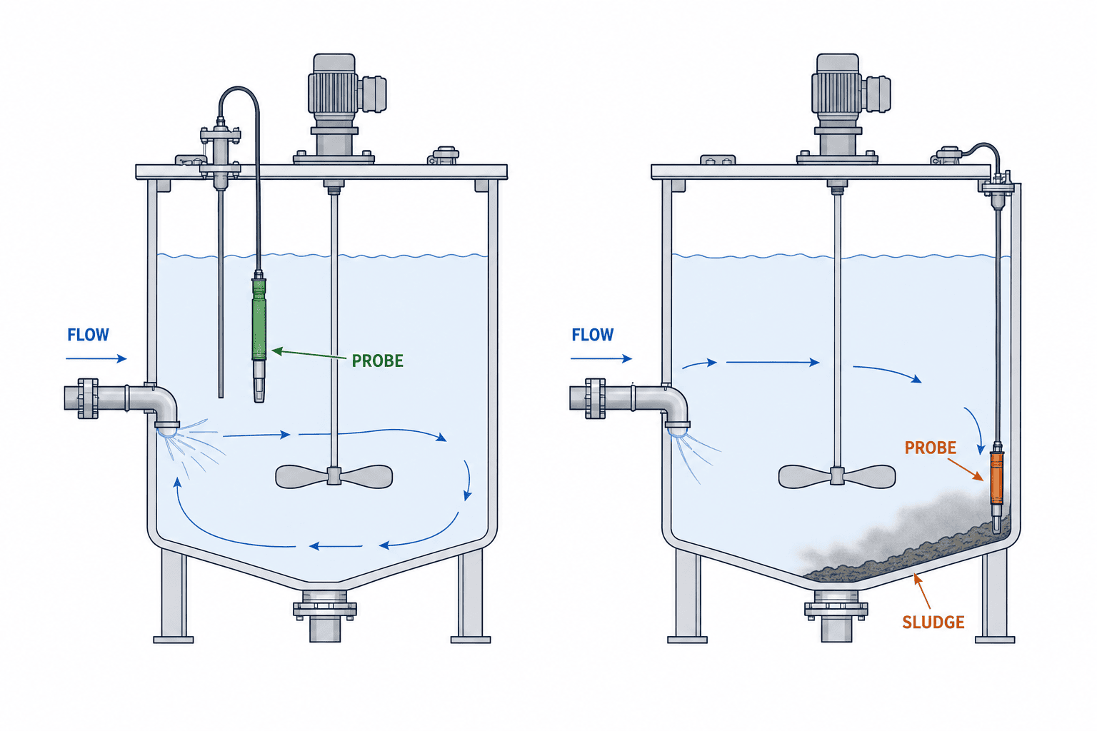
Whether you want to measure pH inside a tank, check post-reaction outflow, or record at the final discharge point determines the location. Placing the sensor in unevenly mixed liquid immediately after dosing risks treating a temporary local concentration as the process representative value. Conversely, placing it far downstream after mixing may delay control response. First, check flow, agitation, retention time, dosing points, and liquid level at shutdown on drawings and onsite.
For immersion types, ensure that both the glass and junction are submerged even at minimum liquid level, avoid sediment at the tank bottom and agitator blade collisions, and confirm safe cleaning locations after removal. For insertion types, check conditions for flow stoppage, empty pipes, bubbles, pressure release, valve isolation, holder removal direction. For bypass types, define abnormal detection for insufficient sample flow and where to return the sample. In open channels, consider waves, foam, debris, and access platforms.
Endress+Hauser’s selection guide distinguishes immersion holders for open tanks/channels and various assemblies for pipes/vessels. Thus, bidding on sensor model numbers alone does not allow comparison of the entire installation. Require equipment lists including holder material, connection ports, seals, extraction/isolation mechanisms, cleaning ports, cable protection, and field installation. Final installation approval is based on site safety procedures.
Incorporate Cleaning, Calibration, and Replacement into the Design
pH electrodes are components that can foul and change calibration characteristics during use. Yokogawa’s maintenance materials treat cleaning and calibration according to fouling as operationally critical. Endress+Hauser’s selection guide also states that lifetime cannot be answered uniformly and depends on selection, cleaning interval, and application. Therefore, do not assume “maintenance-free” or “one-year replacement cycle” as bid premises.
For cleaning design, specify not only what removes fouling, but also who, where, with what gloves/PPE, and how to dispose of post-cleaning liquid. If chemical cleaning is allowed, confirm manufacturer-specified concentration, time, and material compatibility. Frequent cleaning with strong chemicals may accelerate electrode or seal degradation even if fouling is removed. From both safety and lifetime perspectives, first check if water rinsing or gentle cleaning suffices with actual liquid.
Calibration is not just “matching the display value.” Record the standard solution used, expiry, temperature, pre/post condition, zero point/slope, operator, and replacement decision. Use manufacturer-recommended frequency as a starting point, and set field intervals based on drift in actual liquid and process risk. Define procedures for continuing operation with previous values, switching to verification measurement, or manual control in case of calibration failure. For digital electrodes, also check which calibration history items are stored and can be transferred to higher-level systems.
What to Check if Values Drift Immediately After Calibration?
Before recalibrating with new standard solution, distinguish between fouling of the junction and glass, deterioration of standard solution, temperature, cable or connector water ingress, installation position flow bias, and time lag between sampling and online measurement. Even if calibration is successful, slow response in actual liquid makes it unsuitable for control input. Record causes and actions in work history; if the same failure recurs, review electrode model or installation structure.
Specify Transmitter and Signal as a Set
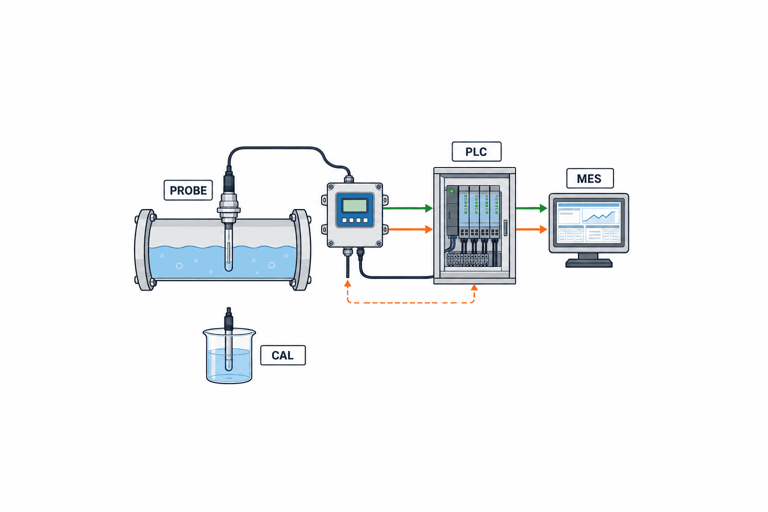
After the electrode come the cable, transmitter, PLC or SCADA, and, if needed, MES or maintenance systems. Before choosing 4–20 mA or digital communication, decide whether only pH value is needed upstream, or also temperature, diagnostics, calibration date, and maintenance status. If reusing an existing transmitter, confirm sensor compatibility by model and firmware with the manufacturer. Physical connector fit does not guarantee measurement.
For analog signals, record pH scaling, current for open circuit/calibration/out-of-range, power loss behavior, isolation, and noise countermeasures in the tag list. For digital communication, record update cycle, timestamp, quality flag, disconnection detection, reconnection, and read/write permissions. Design so that old values are not treated as new measurements when communication recovers. In all formats, use consistent tag ID, unit, and measurement location for display and history.
When passing data to MES, do not try to link process/equipment/lot after the fact. Link measurement time, equipment ID, batch or lot, sensor ID, calibration status, and quality flag, and define rules not to convert missing or maintenance data to “zero.” In wastewater treatment, there may be no lot; in that case, use treatment tank, flow path, operation mode, and sampling ID as axes. By separating raw data and approved correction history, you can trace events for audits or troubleshooting.
Clarify Boundaries When Connecting to Control
When connecting pH to a chemical dosing pump, consider both sensor response speed and chemical mixing delay. If the sensor is slow or too close to the dosing point where mixing is incomplete, acid and alkali may be overfed in pursuit. Physical constraints such as dosing flow, maximum output, rate of change, deadband, and stop at zero flow should be handled on the PLC side. Even if SCADA or MES display/analysis functions stop, ensure safe field operation is possible.
Do not simply state “hold last value” for fault response. Distinguish between electrode removal, loss of sample liquid, calibration in progress, communication loss, and physically implausible rapid value changes. For each, the process owner approves actions such as stopping dosing, switching to validated fixed operation, requiring manual confirmation, or issuing alarms. Not all processes have the same safe state.
In FAT, test not only simulated values but also quality failure flags and recovery sequences to ensure control does not revert to old values. In SAT, verify actual cables, transmitters, PLCs, displays, and history, including field stop/restart. For a broader view of control design, see Water & Wastewater Automation Article.
Items to Include in Procurement/RFP
A request for “complete pH sensor set” may result in proposals ranging from just a low-cost electrode to a full package including retractable holder, cleaning system, transmitter, installation, and commissioning. To enable comparable quotes, clearly specify supply scope and exclusions for each measurement point. Do not fill unknown liquid properties with guesses; mark as “unconfirmed” and assign responsibility for pre-sample testing or onsite verification.
| RFP Item | Vendor Response Required | Acceptance Reference |
|---|---|---|
| Media Compatibility | Reason for selection of glass, reference junction, seal, holder | Actual liquid test, manufacturer documentation |
| Installation Configuration | Installation drawing, dimensions, required isolation/drainage, safe access | Field measurement, construction drawings |
| Signal | Transmitter, output, diagnostics, fault signal and recovery | Tag list, I/O test |
| Maintenance | Cleaning/calibration/replacement procedures, consumables, spares | Procedures, field demonstration |
| Service | Technical support in Thailand, calibration assistance, parts procurement | Contract, handover list |
| Testing | FAT/SAT items, evaluation method, responsibility boundaries | Signed test records |
For price comparison, separate electrode unit price and maintenance cost. Replacement frequency varies by medium and operation; rather than seeking a blanket “X years lifetime” guarantee, estimate labor, downtime, spares, transport/disposal by condition. If requesting lifetime prediction from the manufacturer, have them specify assumed medium, temperature, fouling, cleaning method, and operating hours.
If specifying a brand, state reasons such as compatibility with existing systems or local maintenance standards, and set criteria for equivalents. Competing only on model numbers omits important installation and maintenance items. Place specifications, P&IDs, cable lists, tag lists, calibration procedures, and FAT/SAT sheets under unified version control, and notify all vendors of any changes during bidding under the same conditions.
What to Check in FAT: Desk/Simulation Testing Before Delivery
FAT (Factory Acceptance Test) is the stage to verify electrode, transmitter, signal processing, and upper-level system specifications before using actual process liquid onsite. Using standard solutions or simulated inputs, test display range, temperature input, calibration menus, diagnostics, alarms, communication loss, reconnection, and authority for setting changes. Pass/fail criteria are based on the approved model specification and process tolerances at order; do not apply generic mV or pH tolerances to all devices.
For calibration procedures, check what records are kept before and after work. Confirm how standard solution lot, expiry, temperature, zero point, slope, date/time, and operator are stored, and test that erroneous calibration values are not activated on error. For digital electrodes with calibration data, also test that after sensor replacement, upper-level tags and history are not incorrectly linked to another sensor.
For PLC-connected projects, simulate fault current, quality failure, maintenance, and recovery. Since FAT cannot reproduce pipe mixing time or actual liquid fouling, record these limitations in the test sheet and carry them over to SAT. FAT approval does not guarantee field performance, but reduces basic setting and signal interpretation errors before site delivery.
What to Check in SAT: Actual Liquid, Installation, and Workability
In SAT (Site Acceptance Test), verify that the electrode is sufficiently immersed in actual liquid, that flow and bubbles do not interfere with measurement, and that operators can safely extract, clean, and calibrate. Cross-check installation location and tag against drawings, and trace transmitter display, PLC value, SCADA history, and, if needed, MES value at the same time. For sampling comparisons, conduct under as close conditions as possible, and record temperature changes and time lag after sampling.
Test not only normal operation, but also low liquid level, shutdown, cleaning, startup, chemical switching, power recovery, and communication loss. If all conditions cannot be checked with actual liquid in one day, include observation items and completion criteria for the commissioning period in the contract. Do not approve based only on trend stability; confirm time to return to original value after cleaning, calibration location, required downtime for replacement, and existence of spares.
On the acceptance sheet, record not only “pass/fail,” but also measurement point ID, operating conditions, standard solution or reference meter used, operator, date, configuration file version, abnormal handling, outstanding issues, and correction deadlines. It is important to be able to compare initial performance and installation conditions if the sensor is later changed. If SAT reveals a structure that prevents field work, do not simply shorten calibration intervals; consider changing holders or platforms.
Post-Installation Operation Design and Fault Isolation
After handover, you need more than just normal pH trends. In inspection records, include junction condition, glass fouling, standard solution management, zero point/slope changes, cleaning time, and replacement reasons. When values fluctuate, comparing temperature, flow, dosing amount, agitation, and lab or portable meter readings helps distinguish process variation from instrument failure. Maintenance and process staff should share the same history, not just maintenance making replacement decisions based on numbers.
Calibration failures, response delays, and frequent cleaning may indicate not just electrode quality but also measurement point design flaws. Review field conditions such as stagnant liquid, low levels, air in pipes, or longer-than-expected exposure to hot cleaning liquid. If the same symptoms recur after replacement, consult the manufacturer with the failed unit and operation history, and request reevaluation of the reference junction or installation method.
Instead of evaluating lifetime by a single average value, compare operational burden by measurement point. By tallying cleaning frequency, calibration success, replacement parts, downtime, missing data, false alarms, and manual control switches, you can justify investment in automatic cleaning or installation changes. A plan that incorporates maintenance and quality information into MES is more useful for upgrade decisions than one that only sends measurement values.
Selection Examples by Measurement Point: How to Translate Conditions into Specifications
The following three examples are not product recommendations, but examples of what to write in an RFP. Actual suitability should be determined by actual liquid information and manufacturer model documentation. First, in a neutralization tank with large liquid level changes and sedimentation, placing the sensor near the bottom does not always yield a representative value. Check minimum liquid level and agitation flow lines, avoid areas prone to sediment accumulation, and indicate a position on the drawing where the sensor can be raised for cleaning. Compare electrode candidates based on fouling type and junction cleanability, and observe low level and post-shutdown restart in SAT. If used for chemical dosing control, always treat the sensor being withdrawn as a quality failure.
Second, for return liquid in cleaning processes with high temperature and chemical switching, do not select based only on pH during normal production. Specify cleaning chemical types, maximum temperature and contact time for each process, rinsing timing, and conditions for emptying pipes. Also confirm duration of simultaneous high temperature and high alkali, calibration-possible temperature after cleaning, and procedures during chemical changeover. Whether the electrode is retracted from the flow path or always measuring, required equipment configuration and data loss handling differ. In either case, design tags so that CIP periods are not saved as normal product quality values.
Third, at the final wastewater recording point, in addition to the measurement value itself, the relationship to the sampling point, calibration history, missing data during maintenance, and time synchronization are important. Even if upstream neutralization tank pH is normal, mixing from another flow path can change the final value. Align flow diagrams and sampling procedures, and record comparison conditions between online and lab results. Which discharge regulation applies should be confirmed separately with permit conditions and authority documents; do not infer legal compliance from instrument model numbers.
The common point in these examples is that you cannot select a model based on medium name alone. Use catalog classifications such as “for neutralization tank,” “for CIP,” or “for wastewater” as a starting point, but back up with field conditions via photos, P&IDs, samples, and operation history. If any important condition is unknown in the pre-procurement site survey, clearly state as provisional selection and set a gate for final confirmation based on sample testing or commissioning results.
Furthermore, even when using the same model at multiple sites, you should manage the measurement medium and installation method at each measurement point as exceptions to the standardization rules. While having common spare parts offers significant advantages, if you mechanically apply the same model to processes with different levels of contamination or pressure, it may lead to more calibration failures or early replacements. By listing the application range of standard models, the approvers for exceptions, and the compatibility conditions for alternative models, both the procurement and maintenance departments can make decisions based on the same assumptions. When changing models, be sure to check not only the sensor itself but also the impact on holders, cables, transmitter settings, PLC tags, and maintenance procedures.
When increasing the number of measurement points, consistency in tag naming and drawings is also important. For example, if the physical label on an electrode, the display on the transmitter, the PLC address, and the MES equipment ID all use different names, there is a risk of linking calibration records to the wrong point. During FAT, verify the tag correspondence table, and during SAT, check each physical item and screen one by one. After handover, if any changes are made, keep a record mapping the old and new names to ensure that historical trend data remains continuous.
Frequently Asked Questions on Factory pH Sensor Selection
Can You Compare Manufacturers by pH Sensor Price Alone?
No. Align the supply scope for electrode, reference system, holder, transmitter, cable, cleaning/calibration tools, spares, installation, testing, and local service. Replacement frequency and maintenance time vary by liquid properties and operation, so compare quote assumptions as well. Rather than publishing prices as open market data, it is more effective to present the same RFP to multiple companies based on the specific measurement point conditions.
Is One Type of Electrode Enough for All Factory Wastewater?
Not necessarily. Neutralization tanks, CIP wastewater, cooling water, and final discharge all differ in temperature, fouling, chemical composition, flow, and required maintenance. Use manufacturer application tables to narrow candidates, and verify response and cleaning for fouling-prone points with actual liquid tests. Compare the benefits of standardizing on one model with the risks of using it outside its intended application for each measurement point.
Is Calibration Unnecessary for Digital pH Sensors?
No. Some digital types support calibration history storage and lab calibration, but the fact remains that the glass and reference junction contact the medium. Set calibration frequency based on drift in actual liquid, process tolerance, and manufacturer recommendations. Communication capability and measurement validity are separate checks.
Can You Directly Connect a pH Electrode to Chemical Dosing Control?
Avoid designs where dosing amount is determined solely by sensor value without limit. Consider mixing delay, zero flow, faults, and values during cleaning, and set PLC-side limits and manual recovery conditions. In FAT, verify abnormal signals; in SAT, verify actual liquid and piping conditions.
Summary
Factory pH measurement is not just about buying an electrode; it is about designing the measurement point, including medium, installation, cleaning, calibration, signal, control, recording, and acceptance. Match glass and reference junction selection to the actual liquid, ensure maintenance procedures are reproducible onsite, and document evidence including abnormal cases in FAT and SAT for easier quote comparison and post-installation improvement. Always confirm product-specific temperature, pressure, and pH specs with current manufacturer documentation and model, and check legal requirements for each factory separately.
If you are considering updating a measurement point but do not have complete medium information, installation drawings, or current failure/calibration history, that is not a problem. TOMAS TECH can assist with requirements definition, including data transfer from sensor to PLC/MES. Please contact us to discuss your current situation and project stage.


