



Industrial connector selection cannot start and end with “M12” or “IP67.” A sensor, actuator, replaceable machine module and control cabinet impose different electrical, mechanical and maintenance requirements. A catalogue rating for one component does not establish that the assembled connection will work when mated, survive its environment, or be protected while unplugged. This guide takes a Thai manufacturing plant through a connection-point register, component and cable selection, a comparable RFP, and FAT/SAT acceptance.
Define the disconnect before selecting the connector
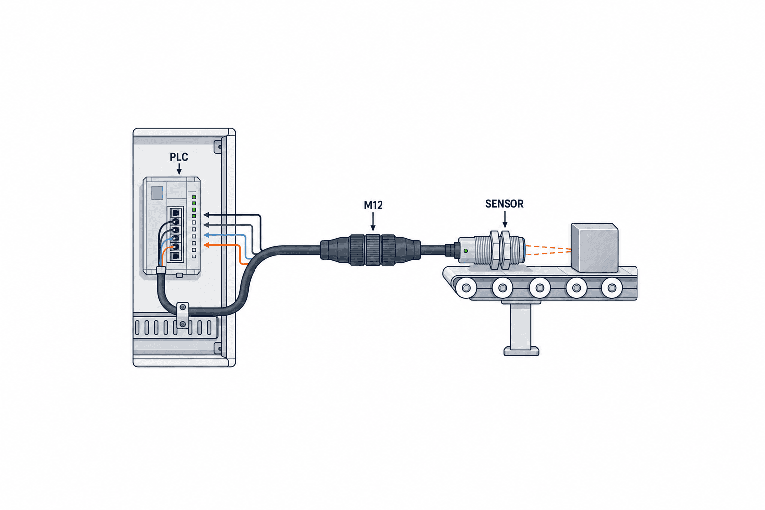
The purpose of a disconnect is to shorten a specific operation: replacing a sensor, removing a conveyor module, changing a jig, or splitting a machine for shipment. A point unplugged twice a week has different mating-cycle and cap requirements from a point disconnected only for major service. Cabinet terminations are a separate design decision; see our control-panel terminal-block selection guide. Here the focus is the interface handled at the machine.
Assign an ID to each disconnect. Record both mating part numbers, pin functions, operating and peak current, voltage, shield termination, cable outside diameter, mounting orientation, ambient temperature, coolant or wash exposure, expected disconnections, and the direction from which a technician reaches it. A list with only the cable-side part cannot prove field compatibility. Manage the fixed receptacle and cable plug as one approved pair, with revisions.
IEC 61076-2-101:2024 describes screw-locking M12 circular connectors with 2 to 17 ways and coding intended to prevent mating between differently coded interfaces. Its scope does not mean every M12 product carries every headline rating. The chosen product data sheet and specified mating combination govern the actual design.
Build a circuit schedule before counting pins
Separate 24 V digital I/O, analog measurement, encoders, industrial Ethernet, actuator power and protective earth. For each circuit list supply type, normal and maximum load, inrush, protection, signal reference, earth and allowable voltage drop. Reserve contacts only for a documented expansion plan; an unexplained “spare” invites later undocumented wiring. Mark whether the pin drawing is viewed from the mating face or wiring face, since combining opposite views can create a mirrored harness.
One multipole connector can make module exchange faster, but combining power and data introduces insulation, noise, miswiring and residual-energy questions. If a modular interface is proposed, obtain the manufacturer’s approved insert combination, separation, PE provision, voltage conditions and housing specification. IEC 61984:2008 provides a safety and test framework for connectors within its stated scope; it is not a substitute for the machine safety assessment. For safety-related circuits, define the state when disconnected and the restart condition after reconnection.
| Connection | Typical function | Decide first | Acceptance evidence |
|---|---|---|---|
| Proximity sensor | 24 V supply and digital output | Existing device interface and pinout | PLC input at each sensor state |
| Analog sensor | Supply and 4–20 mA signal | Signal reference and shield path | Calibrated input and shield continuity |
| Industrial Ethernet | Differential data pairs | Coding, category and shielding | Channel test and error counters |
| Replaceable actuator | Power, command and PE | Continuous/inrush current and safe isolation | Load, temperature and disconnect procedure |
Read voltage and current ratings at the assembled operating point
“24 V, 3 A” is insufficient as a connection specification. State current per contact, number of contacts simultaneously loaded, ambient temperature, wire size, termination method, housing and cable gland. A catalogue maximum may apply under conditions different from a densely loaded connector. Use the manufacturer’s derating curve for continuous load and record the assumptions. The HARTING Han catalogue explains that contact, termination and insulating-material heating constrain current-carrying capacity.
Likewise, check AC versus DC, transient voltage, insulation, protective earth and accessible contacts when unplugged. Never infer permission to disconnect under load from a circular shape or an easy release mechanism. Unless the manufacturer explicitly approves load breaking for that combination, design isolation and a verified de-energized procedure. Account for stored energy in drives, valves and capacitors.
In Thailand, heat near the machine, high humidity and cooling shutdowns can coincide. Check cable jacket, seal and gland temperature limits as well as the connector body. A cold room adds condensation and thermal cycling; a washdown line adds chemical compatibility. If FAT cannot reproduce the maximum ambient condition, combine the product derating data with measured load and document the remaining margin and its limitations.
Specify IP protection for mated and unmated states separately
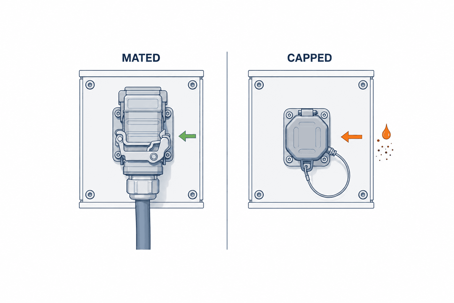
IEC 60529 classifies enclosure protection against ingress. It does not guarantee protection if a cable gland is fitted to the wrong diameter or a locking ring is left loose. Verify the product data sheet’s precise conditions: mated, unmated, or capped. Write both operating and maintenance states into the RFP. A port left exposed after a module is removed may need its own approved protective cap.
For example, Phoenix Contact’s M12 sealing cap is specified for unoccupied field plugs and lists IP65/IP67 for the cap. That supports specifying an appropriate cap, a tether against loss, and a procedure to fit it immediately. It does not turn every uncapped M12 port into an IP67 interface.
IP alone does not establish resistance to cutting oil, cleaning chemicals, metal chips, salt, UV or hot wash cycles. Assess the connector housing, seal, cable jacket, gland and backshell together. Photograph orientations that trap water and check whether a drip loop or revised mounting direction is required.
Use coding and physical layout to prevent wrong connections
M12 thread size is not an interchangeability statement. Coding, contact arrangement, gender, locking method and mating-side standard all matter. The ODVA EtherNet/IP media manual includes assembly guidance and a pin assignment for four-pin D-coded M12. IEC 61076-2-109 addresses an M12 data interface for transmission up to 500 MHz. Neither source supports treating every M12 socket as a universal Ethernet socket: match device port, bandwidth, cable category and shielding.
Several identical sockets on one machine panel still create misconnection risk. Combine distinct keys or codes, physical separation, durable identification, and cable reach limits. A removable label alone can fail under oil and cleaning. For adjacent circuits at different voltages, evaluate the result of a wrong insertion first; if its consequence is serious, change the interface family or physical arrangement.
Push-pull can reduce service time, while screw locking may suit other access and vibration conditions. IEC 61076-2-010:2021 describes push-pull locking based on specified M12 mating interfaces; compatibility still depends on the exact fixed and free sides and coding. Test the proposed pair with gloves, required tools, available clearance and the manufacturer’s torque instruction.
Design the entire shield path
A metal connector alone does not create an effective shield. For industrial Ethernet or sensitive measurement, document the path through cable braid, backshell, gland, connector housing and equipment chassis. Shield termination and earthing must follow the equipment’s EMC design; a blanket rule that every shield is grounded at one end or both ends is unsuitable. Long pigtails, painted chassis surfaces and unmatched glands can defeat the intended path.
List the cable part number, braid preparation, contact point, assembly torque and chassis bond in the drawing. At FAT, measure shield continuity on the finished harness and test analog stability or network error counters while nearby drives operate. Continuity alone does not demonstrate high-speed performance. IEC 60512-28-100:2024 covers signal-integrity methods including insertion loss, return loss and crosstalk; choose channel criteria appropriate to the protocol and installed cable.
Treat cable and connector as one validated harness
Many failures occur behind the contact: excessive bend at the exit, a mismatched cable gland, tensile load, torsion, poor clamp location or repeated flex. Include contacts, inserts, housing, seals, glands, cable, boots, caps and required assembly tools in the harness BOM. A cable outside the gland’s specified range can invalidate the environmental seal even if the connector face is correctly mated.
For moving axes record stroke, speed, acceleration, bend radius, torsion and fixed-point spacing. Our cable-carrier selection guide covers the moving route; at the connector, prevent repetitive bending from concentrating at the cable exit. Add a clamp and a controlled service loop. Support a heavy connector separately if its mass loads a small sensor or bracket.
Field-attachable connectors allow final length adjustment but put stripping, conductor order, crimp, torque and seal quality under installer control. Overmolded cordsets reduce that variation but require the correct length, exit direction and replacement stock. The ODVA manual describes differing D-coded termination methods and calls for following the manufacturer’s assembly instructions and testing the channel. Neither a neat appearance nor a continuity beep is adequate final evidence.
Make mating cycles and serviceability measurable
Estimate annual mating cycles from real changeover and maintenance frequency. Two removals per week may imply roughly 100 per year before allowance for troubleshooting; the actual calendar must be used. Check the selected part number’s stated durability rather than transferring a rating across a whole family. The HARTING Han catalogue gives at least 500 cycles for a particular insert, while TE’s rail M12 product page gives up to 500 for that series. These are examples of product-specific data, not universal M12 limits.
Define inspection criteria for worn contacts, damaged seals, loosened glands and receded terminals. Register the exact spare part and determine local availability and lead time in Thailand. A tested spare harness may restore a line faster than loose contacts and a tool kept at another site. If quick replacement is the business case, time the operation with gloves, covers in place and neighbouring connections present; include misconnection observations in FAT or SAT.
Write an RFP that vendors can answer on the same basis
“Use M12 IP67 or equivalent” leaves too many hidden choices. Supply connection IDs, a circuit schedule, environmental loads, harness drawings and acceptance criteria. Ask vendors to return compliance, deviation, proposed alternative and evidence for each item. Keep unknown site conditions marked as open questions rather than letting each bidder silently assume a different value.
The minimum schedule should include: (1) purpose and disconnect frequency; (2) approved mating pair and interchangeability evidence; (3) pinout, circuit type, voltage, continuous and peak current and PE; (4) coding, gender, lock, orientation, tooling and torque; (5) IP conditions when mated and unmated, cap and cable diameter; (6) temperature, oil, chemicals, wash, dust, shock, vibration, flex and torsion; (7) shield, cable specification, wire markers and length tolerance; and (8) data sheets, drawings, test records, spare parts, warranty and local supply terms.
Compare cost per complete connection or tested harness, including crimp tooling, processing, inspection, caps, rework and spares. Connector-piece price alone can make field assembly appear cheaper while omitting its quality-control work. Require a full housing/contact/seal combination in each proposed BOM.
FAT validates the harness; SAT validates the installation
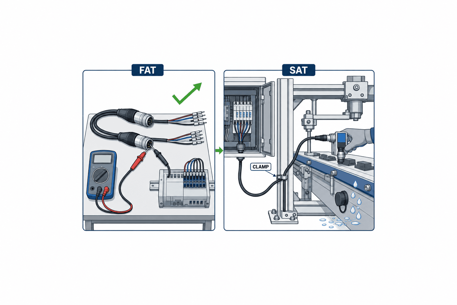
At FAT compare the assembled harness with BOM and drawings: pin numbering, wire colour and markers, length, clamps, cap and torque. Test every conductor for continuity and unintended shorts; verify PE, shield and insulation with a safe method appropriate to the connected circuits. Do not apply a generic high-voltage insulation test through connected electronics or sensors. The designer must state what is isolated during each test.
Exercise sensors and confirm the matching PLC inputs. At representative actuator load, measure voltage drop and temperature. Test the data channel with a suitable tester and protocol criteria; link-up alone is not proof of margin. Run moving parts at representative speed and stroke, observing exit bend, pull and clamp movement. Have an operator demonstrate disconnection, capping and reconnection to expose human-factors failures.
At SAT inspect after transport and installation. The final cabinet and machine positions may change harness length and bend radius. Photograph exposed ports, water and oil exposure, clamp positions, cable loops and interference with covers. Any field extension or retermination becomes a new harness requiring repeated electrical and functional tests. The FAT report cannot stand in for this site check.
Record instrument identification and calibration, date, drawing revision, condition, result, corrective action and retest. Set pass thresholds before the test from the selected product and circuit requirements. There is no meaningful single resistance or signal-quality number for every power, analog and data connection. Document exceptions with owner, interim control and deadline.
Three connection points with different decisions
Fixed 24 V proximity sensor: replacement happens only a few times a year, but cutting-oil splash is present. Start from the sensor’s actual device port, verify supply/output pins, and specify protection for the cable end while the sensor is removed. Include the cap in the BOM and require de-energized replacement in the service procedure.
Quick-change jig: the unit is removed several times each week and mixes signals with solenoid loads. Mating durability, keying, gloves, residual pressure and residual voltage matter more than minimal connector size. Manage the jig ID and drawing revision so all spare jigs share the same pinout; make an actual changeover part of FAT.
Machine-vision Ethernet camera: a motor drive operates close to the metal frame. Select port coding and cable category from the required data link, detail the shield path, test the completed channel and check errors while the drive runs. Any conversion at the cabinet switch is also a documented, tested connection point.
Specify outsourced harness manufacture and revision control
When a contractor builds the harness, define finished length between reference points rather than only raw cable cut length. For a branched harness, show branch position, free length and protective-tube ends. Fit the first article on the actual machine and return any routing correction to the production drawing. A dimensionally correct cable can still be too short once clamps and bends are installed.
Approve substitute cable by strand construction, insulation and jacket, shield design, flex radius, temperature, chemical compatibility and outside diameter, not only conductor cross-section. Check that diameter tolerances remain within the gland’s sealing range. Specify contact plating, crimp barrel wire range, seal and gland as an approved system. Ask the fabricator for crimp tool and die IDs, strip dimensions, visual and pull criteria, torque records, and 100% pin-to-pin continuity testing. Distinguish full inspection from sampling and agree what happens to a batch after a failure.
Mark each delivered harness with ID, revision and manufacturing lot. Keep the connection test and traceability of the principal cable, contact and tooling lots. A spare with an unknown revision may reproduce the same failure. Transfer the drawing, BOM and test form together to the local maintenance team.
After start-up, a sensor substitution may change connector orientation or pinout despite having the same function. Before approval, assess the fixed half, cable half, cabinet I/O, spares, drawings, PLC tags and acceptance tests using the connection ID. Record old/new parts, evidence of compatibility, first affected production lot and retest. The recovery instruction should sequence energy isolation, cleaning, inspection of both mating faces, seal and locking checks, functional test and restart permission. Have a maintenance technician who did not write the procedure try it at FAT. For critical equipment, choose whether to stock a tested complete harness or the parts and qualified tooling based on restoration time.
Common failure modes to stop at design review
“IP67 means safe for every washdown.” It does not establish chemical resistance, hot-water endurance, uncapped protection or correct gland assembly. Specify the wash medium and inspect installed orientation.
“All M12 parts mate.” Check coding, gender, contact count, lock and the exact mating-pair data. Do not approve an alternative from a single-side dimension drawing.
“Continuity proves Ethernet.” It cannot demonstrate pair mapping, shielding or transmission margin. Require a channel test and operating error log.
“A dynamic cable can bend at the connector.” The cable’s flex rating does not authorize a sharp bend, tension or torsion at its exit. Show clamp and service loop on the installation drawing.
“The installer can extend it.” A reterminated assembly has a different quality history. Repeat termination, sealing, electrical and communication tests and update the as-built BOM.
FAQ: industrial connector selection
Can I choose M8 versus M12 by size alone?
No. Match device interface, contacts, current, data requirements, coding, work space, tool access and environment. Confirm the opposing part from the device’s actual port part number.
Are A-coded and D-coded M12 connectors interchangeable?
Different coding is intended to prevent cross-mating. Select by the device port, pinout, cable category, shielding and required performance. If a conversion is needed, document and test the conversion as a separate connection point.
Is an IP67 connector IP67 while unplugged?
Only if the manufacturer’s data sheet specifies that state and the required protective parts are fitted. Often the rating assumes a correctly mated pair. State mated and unmated requirements separately in the RFP.
What percentage current margin should I add?
There is no universal percentage. Use simultaneous contact loading, ambient temperature, wire size, load profile, inrush and the manufacturer’s derating curve. Check assembled temperature under a representative load.
Does a shielded M12 solve EMI by itself?
No. Cable braid, backshell, gland, chassis bond and routing complete the path. Check live analog stability and data error counters in the installed configuration.
What differs between FAT and SAT?
FAT confirms drawings, pinout, finished-harness electrical tests, function and changeover. SAT confirms post-transport mounting, environmental exposure, bend radius, caps and live signals. Retest every field-modified connection.
Summary
Industrial connector selection is the design of a repeatable machine disconnect, not a search for a single catalogue rating. Define each point’s circuit, mating pair, coded interface, mated and unmated ingress protection, environment, shield path, cable exit, mating frequency and service procedure. Require a complete tested harness in the RFP; use FAT for electrical and functional evidence and SAT for the installed conditions. This makes downtime risk and replacement effort visible alongside purchase price.
If your team is planning replaceable modules, sensor harnesses or cabinet-to-machine disconnects, contact TOMAS TECH to discuss the connection-point register and acceptance checklist. The discussion can start before part numbers are fixed.
Primary references
- IEC 61076-2-101:2024, M12 screw-locking connectors
- IEC 60529, IP code
- IEC 61984:2008, connector safety
- IEC 61076-2-109:2014, M12 data interfaces
- IEC 61076-2-010:2021, push-pull locking
- IEC 60512-28-100:2024, signal-integrity tests
- ODVA EtherNet/IP media planning and installation manual
- Phoenix Contact M12 sealing cap
- HARTING Han industrial-connector catalogue
*Standard landing pages establish scope. Confirm numerical ratings against the current data sheet for the selected parts and the site’s safety assessment.*


