


A flowmeter on a circulating header cannot, by itself, tell a factory whether its closed cooling-water loop is leaking: a healthy loop also moves a large volume of water continuously. A useful factory cooling-water leak detection system combines makeup-water balance, pressure trends, selected branch measurements and local wetness detection near pumps and heat exchangers. This guide follows a Thai factory project from the first walkdown to the RFP, factory acceptance test (FAT), site acceptance test (SAT) and operation.
First define which cooling-water circuit is in scope
The term “cooling water” may cover an open cooling tower, a closed chilled-water distribution loop, a dedicated machine circuit and an emergency makeup connection within the same building. Verify the actual valves, bypasses, pumps, expansion tank, makeup lines, drains and vents against the P&ID. Do not assume that pipes with the same drawing color belong to the same hydraulic boundary. A scheduled drain, sampling operation, air purge or fill cycle moves water legitimately; record it before calling the difference a leak.
A stable closed loop ordinarily requires little continuous outside makeup, but “closed” does not mean perfectly sealed in every operating state. Establish baseline makeup events and pressure behavior separately for production, startup, shutdown and maintenance. An open cooling tower has a different balance: makeup is needed for evaporation and blowdown, alongside drift, leakage and changes in stored volume. Increased tower makeup is not automatically a leak in the closed process loop. Confirm the boundary at heat exchangers and shared makeup lines.
Two different water balances
For the open tower, a conceptual balance is makeup ≈ evaporation + blowdown + drift + leakage ± inventory change. For a closed loop, inspect makeup minus documented drains and samples, together with pressure and expansion-tank level under comparable operating conditions. A simple subtraction of large supply and return circulation flows is vulnerable to meter uncertainty, branches, bypasses and unsynchronized clocks. Start with the makeup line, then add branch flow and pressure where the diagnostic question requires them.
EPA WaterSense recommends combining meter and submeter readings, leak-detection devices and visual inspection. The DOE distribution-system guidance similarly discusses reconciling supply with verified use, zone meters and pressure management. These are general water-management principles, not a guaranteed leak threshold for a particular industrial loop. The design below applies those principles to factory equipment and must be validated on site.
Split the job into three diagnostic questions
Ask first whether an abnormal condition exists, next which branch is implicated, and finally where water has escaped. Persistent makeup or pressure decay can flag a candidate. Branch flow, valve positions, operating mode and pressure can narrow the search. Spot detectors, sensing cable and safe visual inspection can localize a wet pump seal, flange or heat exchanger. One sensor type rarely answers all three questions.
DOE notes that permanent monitoring can guide a separate pinpointing method. VEGA’s published pump-room application pairs pressure measurement at a pump with point detection of leaked water from a faulty seal. That is a useful example of layered detection, but its exact hardware is not universal: fluid properties, floor slope and the actual installation must be checked.
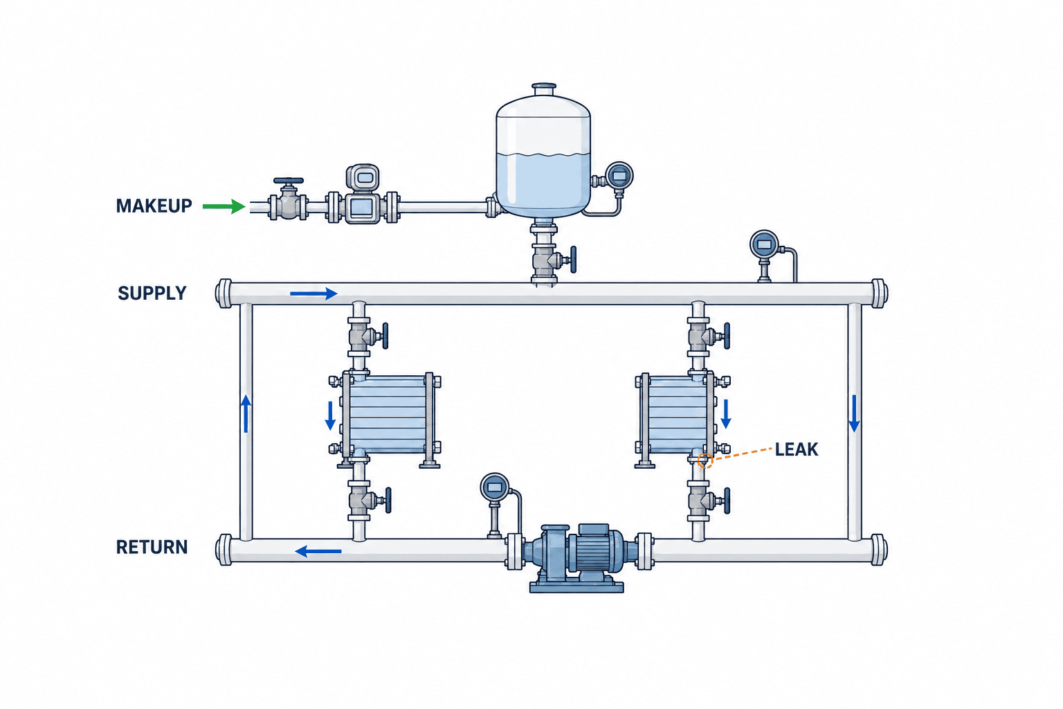
Measure closed-loop makeup before adding many flowmeters
A makeup meter observes new water entering the circuit rather than the much larger recirculating volume. Record its total, instantaneous flow and fill-valve state on a common clock. Characterize normal short filling events by frequency, duration and volume for each operating mode. Link chemical dosing and maintenance to the same event log. A weekly total will not distinguish a small continuous night leak from one planned refill. Conversely, retain data at a resolution justified by the detection time and storage needs rather than collecting every possible sample.
Survey every possible makeup entry. A second header, temporary hose, chiller connection or expansion-tank feed can bypass the chosen meter. Its position upstream or downstream of a valve also changes the monitored boundary. If the line serves another use, separate or account for that use. Mark on the measurement drawing exactly what water volume a meter includes and excludes.
Retrofitting a meter requires a method chosen for the pipe and available shutdown time. Endress+Hauser explains that clamp-on ultrasonic sensors measure from outside the pipe, while selection requires outer diameter, wall thickness, material, coating and fluid sound speed or related fluid data. Nonintrusive installation does not eliminate a site survey. For intermittent low makeup flow, check the candidate’s actual measuring range, low-flow behavior, pulse increment, temperature and installation requirements; compare its zero and totals under site conditions.
Use pressure as supporting evidence
Pressure loss can suggest leakage but does not prove it. Pump cycling, control valves, temperature, expansion-vessel gas pressure, venting and sensor elevation also change pressure. Tag the operating mode and compare like with like. When assessing supply, return and remote branches, account for elevation and calibration. Any isolated pressure-decay test must follow equipment limits and approved isolation procedures.
Coincident signals are more persuasive: frequent makeup plus a slow pressure recovery in the same mode merits investigation. A change in differential pressure during a load change without makeup may instead call for a check of pump and valve control. Synchronize PLC, gateway and server clocks and flag missing samples. Otherwise a delayed data stream can make an effect appear to precede its cause.
Decide which branches deserve instruments
Metering every branch can be expensive and may not improve diagnosis. Rank branches by leak history, pipe condition, access, consequence of downtime and prior makeup events. Group several exchangers if their combined result is actionable; isolate a critical machine if its loss would stop production. A limited pilot on the header and a few important branches is an example of staged design, not a universal meter count. Add more points only after identifying a detection scenario the first stage cannot cover.
For supply-versus-return comparisons, integrate over the same time window and align calibrations and hydraulic boundaries. A bypass, drain or interconnection between the two meters changes the meaning of the difference. If it is comparable to combined measurement uncertainty, report an inconclusive signal and cross-check makeup, pressure and local wetness. An energy-control measurement and a leak-diagnostic measurement can require different low-flow performance and response times. Our cooling-water flow monitoring guide addresses general point selection; this article focuses on a closed-loop leak decision.
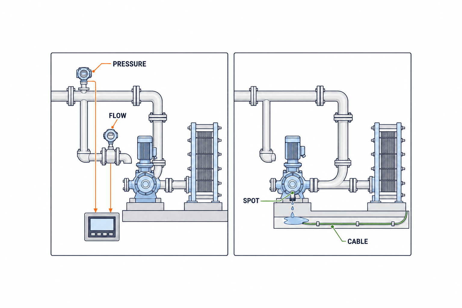
Place spot detectors and sensing cable where escaped water goes
A spot detector suits a low point, drip tray or the floor beneath a pump seal. Sensing cable can cover a longer equipment row or pipe run. Walk the floor to understand slope, drains, insulation, condensation, cleaning water and traffic. A wetness sensor often cannot distinguish cooling water from an air-conditioning drain or wash water by itself. Locate it where it protects a sensitive asset and where maintenance can inspect, clean and replace it.
An internal heat-exchanger leak may never wet the floor. It may require a separate evaluation of cross-contamination, pressure relationships, makeup and fluid quality. This is distinct from cooling-tower water-quality monitoring. Do not claim that a floor cable detects every exchanger failure. Define the leak paths that matter to electrical cabinets, product and production before counting devices.
Separate alarm detection from response
A red dashboard tile is not a response plan. Specify the asset, trigger, delay, clearing condition, priority, recipient, acknowledgement deadline and record. Acknowledging receipt should not mark the fault as repaired. Missing data, sensor failure and uncertain valve position need their own quality states rather than appearing normal. Define who the night shift calls, who may isolate a branch and who can stop production.
Derive initial thresholds from a site baseline. Candidate rules include makeup continuing during shutdown, an increased fill count in a comparable mode, or makeup coinciding with pressure loss. Exclude documented normal events. There is no universal threshold to copy from this article. During commissioning, reconcile every alarm with work records; quantify false alarms, misses and delay before approving production settings.
An automatic shutoff can prevent damage but an incorrect closure can remove cooling from production equipment. Separate circuits that may close automatically from those that only notify an operator. Approve fail position, loss-of-power behavior, manual recovery, pressure surge, emergency-stop interfaces, backflow and the valves’ true isolation boundary. Simulate unsafe accident conditions and bench-test the valve instead of creating a dangerous real leak.
Survey the plant before choosing products
During the walkdown, mark discrepancies between P&ID and pipework, normal bypass positions, makeup entries, expansion tanks, drains and sample points. Gather pump schedules, shift patterns, weekend shutdowns and cleaning dates. If no historic makeup trend exists, use a temporary meter or manual readings to establish one. Inspect condensation, old leak marks, cable routes, inspection access, spare PLC I/O, network and power. The survey report should state unknown valves and uncertain boundaries, not hide them behind photographs.
Write at least three concrete scenarios: a small flange leak in a stopped branch, water from a pump seal onto a floor, and transfer through an exchanger wall into another circuit are examples. For each, record the first expected signal, blind spots, inspection location, required detection time and responder. Only then select sensors. Without scenarios, vendors may quote instrument counts and screens while the acceptance criteria remain undefined.
At this stage, production, maintenance, quality, safety and IT should review the same drawing. Production confirms when a shutdown is possible; maintenance identifies which valves can be closed; quality decides what product to quarantine if water reaches it; safety checks whether leaked water can reach energized equipment; IT confirms how alarms reach the right person. If one department chooses measurement points alone, sensors may work perfectly while nobody can respond during a power or network outage. Record unverified piping and unassigned responsibilities as open items, and resolve them before installation.
Make the RFP a testable specification
Test coolant compatibility before specifying sensors
Do not label all circuit fluids simply “water.” Corrosion inhibitors, biocides, glycol and deionization can affect the detection method. RLE states that its conductive-fluid sensing cable supports specified propylene-glycol/water blends but cannot detect pure deionized water or nonconductive liquids. That statement describes its product, not every competing sensor. Ask each bidder to test a representative sample of the actual coolant, including any planned formulation change.
Consider cleaning and restoration as well as sensitivity. Oil, dust and detergent may reach a floor cable. Make the cable accessible for safe cleaning and replacement. A very large detection zone identifies a wet area but can slow the search; too many tiny zones add wiring and maintenance. Define zones against floor drainage and inspection routes, such as “under pump A” and “exchanger row.”
RLE also shows a controller that connects sensing cable or spot detectors to a BMS through Modbus RTU or BACnet MS/TP. Protocol availability alone does not prove that a particular PLC receives leak, cable-break, communication-failure and timestamp information as required. List those tags in the RFP and test the path at FAT. Restrict control-system write access until the isolation design is approved.
Document leaks that the design cannot detect
Every method has blind spots: a floor detector misses internal transfer, a makeup meter misses unmetered entries, pressure responds to temperature and control, and a branch difference cannot reliably resolve a leak below measurement uncertainty. Document these as design limits rather than leaving them as vague vendor defects. Provide a safe escalation path for inspection, sampling and approved isolation when the alert does not pinpoint a source; operators should not be forced into an unsafe shutdown just because an alarm appeared.
Attach the confirmed hydraulic boundary, pipe sizes and materials, insulation, coolant, temperature, shutdown windows, electrical and network conditions, and the interface responsibility matrix. Replace “real-time leak detection” with named scenarios, a detection-time requirement, normal events to exclude and a defined recipient. If requesting a false-alarm rate, define its observation period and denominator. Distinguish meter specifications expressed as percent of reading from percent of full scale; demand adequate performance in the actual low-flow region.
List sensors, mounts, wiring, panels, gateway, time synchronization, historian, display, access rights, backup, updated drawings, training, spares and support. Align tag names and data exports with the existing PLC or SCADA. If using cloud services, specify how local alarms operate during an outage and how gaps and backfilled data are shown afterward. Separate read-only data collection from writes into the control network.
| RFP item | Owner’s definition | Acceptance evidence |
|---|---|---|
| Hydraulic boundary | Makeup, drains, branches, valves and exchangers | Field-verified P&ID |
| Detection scope | Anomaly, branch narrowing or local wetness | Scenario test matrix |
| Measurement | Low flow, coolant, pipe and calibration | Calibration and field comparison |
| Notification | Shift, communications failure, recovery | Alarm log and delivery test |
| Safety | Isolation authority and power-loss behavior | Interlock record |
| Data | Clock, gaps, storage and export | Tag list and sample export |
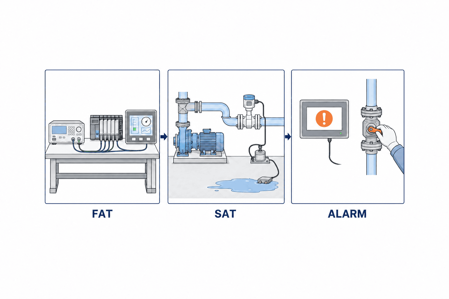
Prove the workflow at FAT and SAT
At FAT, inject simulated flow, pressure, level and fault signals before shipment. Exercise normal fills, sustained makeup, pressure loss, a disconnected sensor and a lost network link. Confirm the correct asset name, notification, acknowledgement, restoration and history. Test equations, units, time windows, clock and export. FAT cannot prove that a sensor is correctly positioned on the real site.
At SAT, check readings with the actual pipes, fluid and operating modes. Operate the makeup valve under an approved procedure and compare valve state with measured flow. Use a permitted simulated wetting test to check spot/cable response and restoration after cleaning. Match pressure trends to actual pump starts, valve changes and shutdowns. There is no need to deliberately create a dangerous leak. Production and maintenance must approve the method, including lockout, isolation and restoration where relevant. Run disruptive tests in an agreed shutdown window.
SAT acceptance means more than a lamp lighting up: record time to detection, message delivery, authority, history, reset, false-alarm handling and whether the maintenance team can perform the response. Identify internal leaks or special modes that could not be tested and assign a later inspection method. Give each open issue an owner and due date; preserve test logs as the baseline for later threshold changes.
Compare costs by coverage, not instrument count
Break cost into survey, pipe and electrical works, devices, integration, screens, tests, training and maintenance. The need to cut a pipe, availability of spare I/O and a nighttime shutdown all change the quotation. A makeup-meter pilot and a system with branch meters, pressure sensors, cable and shutoff valves do not have a meaningful single-point price comparison. Start from the equipment at risk and the tolerable discovery time; request staged options. This guide does not assert a vendor price or payback period.
For each bid, compare covered volume, scenarios detected, likely misses, shutdown work, responsibility boundary, calibration and replacement. A simple floor alarm can be sufficient for one pump room; a critical exchanger may need more than makeup monitoring to locate the problem quickly. Ask bidders to state what they do not detect. For a plant-wide water map, see our factory water-usage monitoring guide.
Avoid a single “installation package” price. Separate the device, mounting, wiring, control-panel modification, commissioning and training for each measurement point. Two pipes with the same diameter can require different work because insulation must be removed and restored, the work platform is higher, a waterproof zone must be penetrated, or an operating machine is close by. Include the right to change alarm rules, history-retention period, data export and disaster recovery in software costs. In the maintenance agreement, establish who tests sensors, what logs are provided during repeated false alarms and the promised onsite response. A cheap system that remains unavailable after a fault may fail to protect the intended asset.
A staged rollout is more than buying the least expensive option first. Stage one records makeup and operating events to find unexplained filling by time, branch or equipment. Stage two adds pressure or branch flow to distinguish candidate causes. Stage three protects high-consequence local locations with spot sensors or cable. At each stage, state what decision becomes possible because of the added measurement. A leak above an electrical cabinet, however, may need local detection immediately rather than waiting for baseline data. Rank work by potential damage and safety.
Review the first 30 days of operation
Reconcile makeup events and alarms with maintenance records daily. If normal chemical dosing triggers alerts, fix event classification rather than simply loosening every threshold. If cleaning water wets a cable, reconsider placement and guarding. If a communication outage creates a blind interval, consider local logging or an independent local alarm. Review confirmation time, time to locate the source, causes of false alarms, repair closure and recurrence rather than celebrating alarm counts.
Add simulated wetting, meter-zero and total checks, pressure-sensor plausibility, contact-list checks and backup restoration to maintenance routines. Set calibration and replacement intervals from the selected manufacturer’s instructions and site conditions. Update the tag register and detection boundary whenever piping changes. Link each sensor to its original scenario so the next operator understands why it was installed.
An incident record needs more than an alarm timestamp. Capture who first noticed it, the observed water location, pump and valve states immediately beforehand, makeup volume, isolation action, production impact, repair point and readings after restart. If photographs are attached, note the camera position so pipe numbers remain identifiable. This record helps distinguish a recurrence from a new branch problem. On screen, keep “suspected leak” separate from “confirmed leak”; do not mark a case repaired before its cause has been established.
When changing a threshold, preserve old and new values, reason, approver and effective time. A temporary alarm mute needs an asset, planned start and end, and an alternative inspection route. An indefinite mute can hide a small leak. Check whether weekends, long holidays or rainy-season humidity require a different review from the weekday baseline. After a sensor has been wetted, inspect it for contamination, damage and broken cable before returning it to service. A system that passed SAT keeps working only if its recovery procedure is practiced.
Frequently asked questions
Can circulation flow alone identify a cooling-water leak?
Often it cannot distinguish normal circulation from leakage. Combine makeup, pressure, operating state and local detection. For branch supply/return differences, account for meter uncertainty and the exact hydraulic boundary.
Can an existing pipe be monitored without a shutdown?
An external clamp-on meter and floor detector may reduce pipe work, but surveying, installation, calibration, power, communications and safe access remain necessary. An inline instrument or shutoff valve may require an outage.
Does increased makeup always mean leakage?
No. Exclude filling, venting, sampling, drains and maintenance first. Evaporation and blowdown belong to the open cooling tower’s normal balance and must not be confused with closed-loop leakage.
How much does a leak detection system cost?
The answer depends on pipe conditions, meter type, branches, PLC integration, notification and isolation scope, testing and training. Ask bidders for options against the same scenarios and acceptance criteria before comparing prices.
What is the difference between FAT and SAT?
FAT tests simulated inputs, logic, alarms and history before delivery. SAT tests the actual pipes, fluid, modes and recipients on site. Document safe isolation and conditions not tested at both stages.
Summary
A closed-loop cooling-water leak system begins with a verified circuit boundary. Use makeup and pressure to flag an anomaly, selected branches and local detectors to narrow and locate it, and an agreed response to prevent damage. Define scenario-based requirements in the RFP and prove them at FAT and SAT. Keep the open tower’s evaporation and blowdown balance separate from closed-loop loss.
If your Thai factory is still mapping measurement points, available shutdown time or the RFP scope, you can contact TOMAS TECH with a current piping sketch and the leak scenarios you want to address. A conversation before device selection is welcome.
Sources
- U.S. EPA WaterSense at Work, Section 2.3: Leak Detection and Repair
- U.S. EPA WaterSense at Work, Section 2.2 (2023)
- U.S. DOE FEMP, Distribution System Audits, Leak Detection, and Repair
- U.S. DOE FEMP, Distribution System Leak Detection
- Endress+Hauser, Ultrasonic flowmeter sensors
- Endress+Hauser, Proline Prosonic Flow W 400
- VEGA, Pump room pressure monitoring and flood protection
- RLE, Conductive Fluid Sensing Cable
- RLE, BMS-LD3Z


