


A common pitfall in selecting acoustic cameras for compressed air leak detection is making purchase decisions based solely on the detection range listed in the specifications, while overlooking factors such as factory noise, accessibility to piping, and post-repair verification methods. This article provides concrete guidance for those issuing RFQs at manufacturing sites in Thailand, covering everything from organizing survey conditions to PoC, FAT/SAT, and handover to maintenance.
For the wider repair and recurrence-prevention programme, see our compressed-air leak strategy guide. This article focuses on camera procurement and acceptance.
1. On-Site Evaluations Essential for Purchase, Rental, or Outsourcing Decisions
When introducing acoustic cameras or ultrasonic detectors for compressed air leak detection in Thai factories, the optimal choice among purchase, rental, or outsourcing (service use) depends on a multifaceted evaluation—not just initial costs or catalog specs. Factors such as actual operational practices, available personnel, maintenance structure, training, and ongoing costs must all be considered. Below are the key decision points, recommended records to keep, and concrete comparison methods.
Inspection Frequency & Site Accessibility
We recommend a planned inspection route to sustain a leak-repair program. For savings evaluation, compare pre- and post-repair flow and power under comparable operating conditions (US DOE evaluation protocol). Owning or renting a camera allows the site to choose its inspection schedule; outsourcing requires agreement on access, timing and response.
In addition, in-house inspections simplify procedures for access permits and safety training. Outsourcing requires safety orientation and entry procedures each time, increasing the on-site burden.
Staffing & Repair Structure
With ownership or rental, on-site staff often double as leak detection operators, making device usability, training costs, and skill retention critical. Operating an acoustic camera or imager requires knowledge of frequency band selection, operation in noisy environments, and distance settings (FLIR Official Guidance). Outsourcing reduces training burden since specialists conduct inspections, but your organization must still manage repair response and communication of findings on-site.
Training, Maintenance, and Repair Costs
Ownership entails initial and refresher training, firmware updates, regular inspections, and repair costs in case of device failure. In high-temperature, high-humidity, or dusty environments, the risk of equipment failure is higher. Rental often includes maintenance and repair, but for long-term use, cumulative costs may approach those of purchase. Outsourcing eliminates device management and training costs but may limit inspection frequency and coverage, making ongoing improvement activities difficult.
Key On-Site Items to Compare & Record
For effective decision-making, record and compare the following:
- Inspection frequency and coverage (flexibility with in-house, limitations with outsourcing)
- Number of staff, skill levels, training history
- Device usability, portability, on-site suitability (detection accuracy in noisy environments, weight, battery life, example specs: Fluke ii900/ii910)
- Repair and update costs, response speed
- Outsourcing service details (inspection coverage, report quality, emergency response availability)
- Status of repairs and improvements based on inspection results
It is recommended to record both quantitative data (inspection counts, number of repairs, training sessions) and qualitative data (ease of operation, clarity of reports), and use these in comparison tables or annual reviews.
Example Decision Scenarios
For small sites or limited inspection targets, spot outsourcing may suffice. For multiple sites or large-scale factories, in-house operation is more cost-effective and flexible. Conversely, if there is a clear shortage of staff or skills, outsourcing to specialists is more realistic than forcing in-house operation.
2. Detection Range and Limitations of Acoustic Cameras
Acoustic cameras have revolutionized on-site visualization of compressed air leaks, but it is crucial to understand their characteristics and limitations and to use them appropriately alongside other measurement methods.
What Acoustic Cameras Can Detect
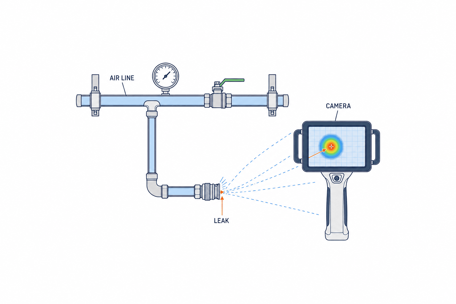
Acoustic cameras analyze the spatial distribution of sound pressure using multiple microphone arrays and superimpose leak sound sources onto images. FLIR guidance identifies 20–30 kHz as useful for separating leak sound from factory noise and 10–30 kHz for longer-distance detection (FLIR Official Guidance). High frequencies attenuate rapidly with distance, so they are best for high-precision, close-range localization.
This allows for rapid pinpointing of leaks even in complex piping or cluttered environments, and recording leak images for repair planning and reporting. U.S. DOE guidelines also recommend managing leak detection and repair records using ultrasonic detection (DOE Sourcebook).
What Acoustic Cameras Cannot Detect
Acoustic cameras directly provide only “sound source location” and “sound pressure intensity.” They do not directly measure actual leak flow rates (e.g., L/min or Nm³/h). FLIR documentation notes that leak size and cost estimates depend on distance and operational settings, and Fluke’s LeakQ estimates leak size based on sound pressure and distance. Neither provides actual measured flow rates (FLIR Manual, Fluke Manual). There is also a risk of false positives due to reflected or background noise; detected hotspots are not always actual leaks. Locating sources behind obstacles is also challenging.
Detection range and accuracy in catalogs can vary greatly depending on site conditions (noise, obstacles, temperature/humidity, etc.), and manufacturer specs are reference values under ideal conditions (Fluke Datasheet).
Differences and Complementarity with Flow Meters
Flow meters measure flow inside piping and are useful for before-and-after repair evaluations under controlled conditions. However, installation locations are limited, require construction, and simultaneous monitoring at multiple points is difficult. Acoustic cameras can non-contact scan wide areas quickly and excel at pinpointing leak locations, but cannot directly measure flow. Since their roles differ, the realistic approach is to use an acoustic camera to locate leaks, then measure details with a flow meter as needed. For details on selecting flow meters, see here.
On-Site Records and Procedures
During acoustic camera inspections, it is recommended to record the following:
- Date/time of imaging, responsible staff
- Device model, frequency band settings, sensitivity
- Leak location images (with sound source overlay), location on piping diagrams
- Imaging distance, site noise conditions (dB values, main noise sources)
- Detected sound pressure level, hotspot intensity
- Piping material, shape, presence of obstacles
- Estimated leak size and cost (clearly marked as estimates, with settings recorded)
- Additional flow meter or pressure gauge measurements as needed
The basic procedure: safety confirmation and device setup (frequency, sensitivity, distance) → scanning → hotspot recording → re-confirmation or multi-angle imaging as needed → compiling repair lists and post-repair re-inspection.
Operational Considerations
The effectiveness of acoustic cameras depends heavily on site environment and equipment structure. DOE evaluation methods require baseline and post-repair leak inspections under comparable operating conditions, combined with actual flow and pressure measurements (DOE UMP Chapter 22). Always cross-check leak and cost estimates from acoustic cameras with on-site data, and clearly indicate they are estimates.
3. On-Site Conditions to Organize Before Requesting Quotations (RFP)
When considering the introduction of acoustic imagers or ultrasonic cameras for compressed air leak detection, accurately understanding and organizing on-site conditions before issuing an RFQ is key to proper equipment selection and efficient operation. Especially for maintenance and procurement staff at Thai factories, it is important to summarize the following five points:
1. Piping Specifications, Pressure, and Operating Hours
These are site conditions we recommend gathering before the RFP. The ISO 11011:2013 abstract describes assessment of compressed-air supply, transmission and demand; it does not prescribe these RFP fields.
Example Record Items
- Piping material, diameter, length
- Pressure range (normal, maximum)
- Operating hours
- Installation location (ceiling, floor, along wall, etc.)
2. Distance and Obstacles
The distance from the camera to the piping and any obstacles (walls, machines, shelves, etc.) between them greatly affect detection accuracy. Fluke and FLIR official materials emphasize the importance of distance and obstacles (Fluke Manual, FLIR Guidance).
Example Record Items
- Distance from inspection point to piping (in meters)
- Type and presence of obstacles
- Piping height
- Accessibility (need for ladder, lift, etc.)
3. Sound Environment
Background noise in the factory (machinery, ventilation fans, etc.) affects detection performance. The 20–30 kHz band is effective under factory noise (FLIR Guidance), but be sure to record main noise sources and their time periods, and check noise conditions during planned inspection hours.
Example Record Items
- Main noise sources
- Noise occurrence time periods
- Noise level (dB value)
- Frequency band (check using analysis apps, etc.)
4. Repair and Shutdown Availability
For post-detection repairs, you must coordinate equipment shutdown dates, secure personnel, and adjust safety procedures. The DOE also recommends clarifying repair plans and schedules (DOE UMP Chapter 22).
Example Record Items
- Available shutdown dates and times
- Required personnel and qualifications for repair work
- Safety procedures and permit status
5. Data Management Policy
We recommend defining leak IDs, storage formats and links to maintenance history before requesting bids. The ISO 11011:2013 abstract addresses documentation of system-assessment findings and an estimated energy saving, not a prescribed leak-location or cost ledger.
Example Record Items
- Data storage format (JPEG, CSV, PDF, etc.)
- Storage location and administrator
- Method for linking with maintenance history (e.g., CMMS)
- Viewing and sharing permissions
Example On-Site Inventory Table
| Piping System | Material | Pressure Range | Distance | Obstacles | Noise Source | Noise Time | Shutdown Day | Data Management |
|---|---|---|---|---|---|---|---|---|
| Main Line 1 | Iron 25A | 0.7 MPa | 5 m | None | Compressor | 8:00–20:00 | 2nd Sat | Excel/Server |
| Branch Line 2 | Resin 20A | 0.6 MPa | 3 m | Shelf | Press Machine | 8:00–17:00 | 4th Sun | PDF/Cloud |
Operational Notes
Accurately understanding on-site conditions is the foundation for equipment selection, introduction, and operation. Depending on distance or obstacles, additional equipment may be needed, and ignoring noise environments increases the risk of false positives or missed detections. Always follow on-site safety rules during surveys, and never perform dangerous operations (such as loosening joints) on live piping.
Such thorough preparation is the key to optimal equipment selection and building a safe and efficient operational system.
4. Evaluation of Frequency, Distance, Noise, Reflection, and Best Practices for Field Documentation
The performance of acoustic imagers in compressed air leak detection is heavily influenced by frequency range, detection distance, in-plant noise, and reflective environments. Effective field utilization requires accurate assessment of these factors and consistent, reproducible documentation practices.
Selecting Frequency Range and Field Application
Acoustic imagers primarily detect leak sounds in the ultrasonic range above 20 kHz. According to FLIR guidance, the 20–30 kHz range is effective for distinguishing leak sounds in many industrial noise environments, but this is only a guideline—the optimal frequency range varies by site. The 10–30 kHz range is relatively suitable for long-distance detection, while higher frequencies attenuate more in air and are better for close-range evaluation (FLIR Official Guidance).
Devices like the Fluke ii900 (2–52 kHz) and ii910 (2–100 kHz) offer wide frequency ranges, allowing flexible adjustment to match site conditions (Fluke Specifications).
Detection Distance, Sensitivity, and Field Noise
Lower frequencies attenuate less in air and are suitable for longer-range detection, but overlap with plant noise increases the risk of false positives. Higher frequencies are better for detecting small leaks at close range, but detection becomes more difficult as distance increases. The Fluke official manual recommends selecting the frequency range according to site distance and noise conditions, and determining optimal settings for each site (Fluke Manual).
Leakage estimation (e.g., LeakQ) is based on sound pressure level and distance, so always record the detection distance to enable accurate comparisons and follow-up investigations under consistent conditions.
Noise Environment and Noise Filter Utilization
If plant noise from compressors or conveyors interferes with leak detection, the 20–30 kHz range is often effective, but the optimal range must be adjusted for each site (FLIR Official Guidance). The Fluke ii900/ii910 features frequency band narrowing to reduce background noise impact. It is also effective to inspect across multiple frequency bands, select the setting with the highest contrast, or perform additional checks when equipment is stopped.
Reflection and False Detection Countermeasures
Factory walls and machine surfaces can reflect sound waves, causing false hotspots. The Fluke manual recommends re-measuring from different angles to prevent false detections due to smooth surface reflections, and recording the distance and angle to the target or wall if reflection is suspected (Fluke Manual). Observing from only one direction increases the risk of misidentification; always check each location from at least two directions to eliminate reflection effects.
FOV (Field of View) and Battery Operation
The device’s field of view (FOV) determines the area covered in a single scan. Verify the FOV specified in the datasheet and develop an optimal scan plan based on the size of the site and inspection areas. For battery operation, check the official specifications for continuous run time and charging methods in advance. Prevent battery depletion during work by preparing spare batteries and a charging plan.
Example Field Documentation Items and Procedure
| Item | Example Check Content | Example Record |
|---|---|---|
| Frequency Range | Which range is optimal | 28 kHz |
| Detection Distance | Measured distance | 4.5 m |
| Noise Environment | Noise level / main sources | 85 dB / compressor |
| Reflection/Obstacles | Reflection risk, wall material, angle | Metal wall / 30 degrees / rechecked |
| FOV/Scan Coverage | Coverage per scan, number of scans | 120° / 3 times |
| Battery Level | Battery at start/end | 90% → 60% |
The recommended procedure: confirm noise environment → set frequency range → measure distance → observe from multiple angles → fill in record sheet → check battery level. This enables field personnel to conduct accurate and efficient leak surveys.
5. Reproducibility and Safe Operation of Field Survey Routes
The effectiveness and sustainability of compressed air leak surveys depend on designing reproducible survey routes and a robust documentation system. Especially in Thai factories, with complex piping networks and diverse equipment, vague survey points or routes can lead to missed leaks, record confusion, and rework during follow-up surveys.
Route Design and Tagging
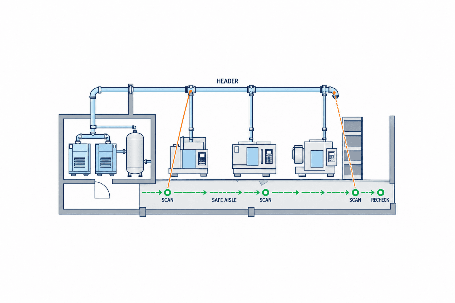
Survey routes should comprehensively follow the flow of air from compressors and headers through branch pipes to each usage point. Clearly indicate piping paths, branches, valves, and instrument locations on floor plans, assign unique IDs to each route and survey point (e.g., H1-B2-P5), and install durable tags on-site. This ensures that any operator can reliably identify the same route and survey point.
Documentation Items and Survey Procedure
Record the following during surveys:
- Route ID and Survey Point ID
- Survey date/time and responsible personnel
- Operating status (normal/stopped/partial operation)
- On-site pressure gauge reading
- Detection distance (measured by tape or laser rangefinder)
- Presence and condition of valves, filters, etc.
- Set frequency range (e.g., 20–30 kHz, see FLIR Official Guidance, Fluke Manual)
- Presence and characteristics of leak candidates (screenshots, site photos, etc.)
- Results of rechecks from two directions
We recommend preserving readings and images so the repair team can locate and recheck each defect. For energy evaluation, pair these records with comparable before-and-after flow and power measurements (US DOE protocol).
Safe Survey Operation
Surveyors must always secure a safe working position. For high places, confined spaces, or around operating machinery, obtain work permits, assign assistants, and strictly enforce access restrictions. Do not loosen operating pipes or joints to intentionally create leaks. When measuring distances or setting up equipment, consider equipment movement ranges and air blowout risks, and avoid awkward postures or working in unreachable locations.
Two-Direction Confirmation and Distinction Between “Candidate” and “Confirmed Repair Target”
Acoustic camera surveys are prone to false positives due to reflections and noise. Always recheck from different angles; only locations showing consistent responses from both directions are classified as “leak candidates.” Taking into account on-site pressure, operating status, and noise, further confirm with multiple checks or with soapy water (only in a safely stopped state) before classifying as a “confirmed repair target.”
Ensuring Operational Reproducibility
Survey route and point information must be linked to floor plans. When equipment is modified, always update IDs and tags and maintain correspondence with past records. Centralized management of survey and repair history prevents recurrence and missed unrepaired points.
6. Acoustic Camera RFP Specifications, Field PoC, and Deliverables
When procuring acoustic cameras, the RFP (Request for Proposal) must specify site-oriented mandatory requirements, PoC (Proof of Concept) testing, deliverables, and IT/support structure in detail. Go beyond catalog specs and general standards—set conditions that emphasize field verification and safe operation.
Mandatory Performance Requirements
- Frequency Range & Sensitivity: Must allow selection of frequency range suitable for the target and demonstrate performance in plant noise during PoC.
- Detection Distance, Field of View, Resolution: Must detect leaks from representative distances under actual equipment layouts and noise conditions in the site PoC (Fluke Specifications).
- Data Recording & Output: Must export leak location images, acoustic spectra, and estimated leakage/cost (FLIR Manual) in CSV and standard image formats.
On-Site PoC Test Conditions
- On-Site Testing with Actual Equipment: Verify detection capability using actual plant equipment and piping under real noise conditions, with known leak points (using permitted test fixtures only). Perform data export and analysis (DOE Evaluation Method).
- Example Test Items: Detection at representative pipe diameters, materials, and distances; check for false detections (reflections, noise sources); demonstrate data recording procedures; allow site staff to operate the device.
- Pass/Fail Criteria: No fixed numerical benchmarks; require that “known leaks can be detected and recorded under normal operating conditions in the on-site PoC,” with factory maintenance staff present for evaluation.
Options, Accessories, and IT Security
- Options: AI-based automatic classification, cloud integration, CMMS integration API.
- Accessories: Spare batteries, dedicated case, locally compatible charger.
- Data Ownership & Security: Must support data export; data ownership remains with purchaser. For cloud use, specify storage location, access rights, and return of data upon contract termination. State requirements for authentication/encryption on firmware updates and external connections, and supplier cooperation with IT department review.
Maintenance, Warranty, and Training
- Warranty & Repair: Local repair support in Thailand, loaner units, clearly stated warranty period and coverage.
- On-Site Training & Manuals: Operation training in Thai or English; user manuals in local language.
Deliverables
- Product specification sheet (including measured values)
- PoC test report (demonstrating detection, recording, and export at the site)
- Operation and maintenance manual
- Warranty certificate and support contact
- Full list of accessories
RFP Sample Clauses (For Attachment)
“`
- The proposed acoustic camera shall demonstrate leak localization in the agreed site scenarios and export images and inspection records in an agreed format. Any leak size estimate shall be identified as an estimate.
- Supplier shall conduct an on-site PoC test under normal operation to verify detection capability for representative leak points, with factory maintenance staff present.
- All recorded data remains the property of the purchaser. If cloud services are used, data location and access rights must be specified.
- Warranty, repair, and user training must be available in Thailand, with user manuals in Thai or English.
- Optional features such as AI-based leak classification, cloud integration, and spare batteries should be quoted separately.
- Deliverables include product specification sheet, PoC test report, user manual, warranty certificate, and full list of accessories.
“`
Conclusion
In your RFP, specify performance requirements focused on field PoC, data recording/export, IT and support structure, and deliverables in detail. This ensures selection based on true site suitability, not just catalog comparison. Content that balances field verification and safe operation is key to successful adoption in Thai factories.
7. Positive, Negative, and On-Site Scenarios to Verify in PoC
In Proof of Concept (PoC) for compressed air leak detection technologies, it is essential to strictly observe on-site safety and operational procedures while thoroughly evaluating effectiveness, reproducibility, and false detection risks from multiple perspectives. Notably, combining three scenarios—positive (known leak present), negative (no leak), and real on-site environments—significantly improves the accuracy of adoption decisions. Below, we explain specific points for PoC design and implementation in Thai factories.
Positive Scenario: Reproduction of Controlled Known Leaks
The positive scenario assesses whether leak detection devices can accurately detect and locate known leaks. For safety and quality management, it is strictly prohibited to manipulate live piping or joints to create leaks. Instead, always install a dedicated test jig (with holes of known size or adjustable valves) approved by the plant maintenance manager, temporarily integrating it into the compressed air supply line. Only authorized technicians, following safety procedures, should install and operate the jig, and must accurately record pressure, flow rate, hole diameter, and detection distance at the time of leak occurrence.
The site engineer should approve safe fixture aperture, pressure and test repetition based on the plant procedure. Repeat the approved tests and record detection consistency; do not adopt an unsourced universal test setting.
Reference: US DOE Compressed Air Sourcebook
Negative Scenario: Negative Control with Completely Sealed Jigs
In the negative scenario, use sealed jigs or new piping sections without leaks to verify that the detection device correctly identifies “no leak.” Conduct measurements under the same conditions as the positive scenario (pressure, distance, noise), and record in detail whether any false detections or spurious hotspots occur. This helps identify tendencies for misjudgment due to ambient noise or reflections, clarifying operational precautions.
Reference: FLIR Acoustic Imager Guidance
Actual On-Site Scenario: Field Verification in Diverse Piping Environments
Factory sites include a variety of environments, from quiet main headers to noisy production lines and complex piping with many branches and reflections. In the PoC, evaluate detection performance in the following representative on-site scenarios:
- Quiet Header Pipes: Leak sounds are clear, making it easy to confirm the basic performance of detection devices.
- Noisy Production Lines: Environments with overlapping machinery and air tool noise. Frequency settings in the 20–30kHz band can be effective for factory noise resistance (FLIR Acoustic Imager Guidance). However, the optimal band varies by site.
- Piping with Many Reflections/Branches: Higher risk of false detections due to sound wave reflections and interference; actual detection accuracy and reproducibility must be evaluated (Fluke ii900/ii910 User Manual).
For each scenario, record detection distance, frequency band, noise level, detection location accuracy, and presence/absence of false detections in detail, confirming reproducibility through multiple measurements.
Evaluation Criteria and Blind Testing
PoC evaluation criteria should be agreed upon in advance between maintenance and procurement teams to avoid subjective assessment. Clearly specify the following items, and where possible, introduce blind testing (where the detection operator is not informed of leak information) to enhance objectivity.
- Leak detection presence (True/False)
- Location error distance
- Presence of false positives
- Reproducibility (consistency under identical conditions)
Record evaluation results qualitatively as “detection successful,” “location identified,” “no false detection,” etc. Numerical pass rates and thresholds should be determined later based on on-site measured values.
Specific Items to Record
During PoC, always record the following:
- Date of implementation, responsible personnel
- Type of test jig, leak size, pressure, flow rate
- Detection device model, set frequency band
- Detection distance and angle
- Background noise level (dB value if possible)
- Detection results (presence/absence, location, false detection)
- Detection images and data files
These records form the basis for decisions on adoption and for establishing operational rules.
Summary
In PoC, always prioritize safety and combine the three scenarios of “controlled known leak,” “completely sealed control,” and “actual site environment.” Conduct objective evaluations based on agreed criteria and detailed records. This ensures reliable verification of the practical applicability of compressed air leak detection devices on site.
8. Linking Leak Volume and Cost Estimates to Investment Evaluation
Estimating the volume and cost of compressed air leaks is essential for repair planning and investment evaluation (ROI). However, “per-location estimates” from acoustic imagers must always be cross-checked with on-site data and should not be relied upon blindly. This section organizes the characteristics and limitations of estimation methods, consistency with system-wide measurements, record items, and how to link to investment evaluation.
FLIR Acoustic Camera Estimation Methods and Cautions
The FLIR Si1-LD manual lists distance, leak type, cost, specific power, utilization, temperature and humidity among the settings used for leak analysis; it does not list a user-entered pressure setting. Displayed leak rate and cost are estimates influenced by distance and settings. The FLIR selection guide discusses 20–30 kHz for separation from factory noise and 10–30 kHz for longer-distance detection as context-specific guidance.
Fluke LeakQ Estimation and On-Site Records
Fluke ii900/ii910’s LeakQ estimates a leak scale index from 0 to 10 based on sound pressure and distance (Fluke Manual). However, estimates are susceptible to background noise, distance setting errors, and reflected sounds, and values fluctuate with on-site conditions. Given the frequency band specifications (ii900: 2–52kHz, ii910: 2–100kHz), detection performance cannot be guaranteed across all sites (Fluke Datasheet).
On site, record photographs and locations, measurement distance, frequency band, background noise, camera settings such as specific power and utilization, estimates, date and inspector. Record pipe pressure separately as a site operating condition, not as a camera input.
Consistency Between Individual Estimates and System-Wide Measurements
The ISO 11011 abstract describes system-wide assessment and an estimate of energy saving. For comparable pre- and post-repair flow and compressor-power measurements, use the US DOE evaluation protocol; the ISO abstract does not prescribe a flow-meter trend baseline.
For flow meter selection and measurement methods, refer to this page.
Individual estimates are useful for prioritizing repairs and understanding leak distribution, but always confirm consistency with system-wide measured values when calculating ROI.
Evidence Chain and Investment Evaluation
For reliable investment evaluation, record the following evidence chain:
- Leak Detection: Identify leak locations with an acoustic imager (record photos, locations, and conditions)
- Individual Estimation: Record camera settings such as distance, leak type, specific power and utilization, and the estimated leak rate and cost; record pipe pressure separately as a site condition
- System-Wide Measurement: Measure flow and power consumption before and after repairs (specify conditions)
- Comparison and Consistency Check: Compare the sum of individual estimates with changes in system-wide measured values; re-examine if discrepancies exist
- Investment Evaluation Input Table Preparation: Create an input table showing supporting data
Example Investment Evaluation Input Table
| Item | Value / Record Content | Basis / Remarks |
|---|---|---|
| Flow Before Repair | e.g., 1,200 Nm³/h | Actual flow meter measurement |
| Flow After Repair | e.g., 1,050 Nm³/h | Same as above |
| Sum of Individual Leak Estimates | e.g., 180 Nm³/h | Acoustic camera records |
| Specific Power | e.g., 0.12 kWh/Nm³ | Compressor specs / actual measurement |
| Annual Operating Hours | e.g., 6,000 h | Operation records |
| Repair Cost | e.g., total parts and labor | Quotations, etc. |
| Annual Energy Savings | e.g., 108,000 kWh | Flow difference × specific power × hours |
| Annual Cost Reduction | e.g., local electricity rate × savings |
The 108,000 kWh/year figure is only the arithmetic example: 150 Nm³/h × an assumed 0.12 kWh/Nm³ × 6,000 hours. Actual power savings depend on compressor controls and load and must be checked with before-and-after power measurements.
Do not calculate ROI based on estimates alone; always evaluate using measured values, supporting data, and recorded images.
Summary
Estimating leak volume and cost leads to reliable investment evaluation when combining individual estimates with system-wide measured values and retaining an evidence chain. Accurately record the basis for each measurement and estimate, and avoid double-counting or overreliance on estimates.
9. Vendor Comparison Tables: Standardize Beyond Price
When selecting acoustic imagers or services for compressed air leak detection, it is essential to compare not just price but also on-site operability, record-keeping, support system, and total cost of ownership (TCO). Below are key points for building and utilizing vendor comparison tables (matrices) tailored to Thai factory requirements.
Comparison of Scenario Detection Capabilities
For each on-site detection scenario (e.g., under noise, at long distances, in confined spaces), document catalog specs (e.g., detection frequency band, recommended distance) and whether each model can actually handle these conditions. Frequency bands such as Fluke ii900/ii910’s 2–52kHz/2–100kHz are product specifications, but real-world usability must be a required evaluation item due to the impact of site noise and reflections (Fluke Datasheet).
Verification of False Detection and Hotspot Mitigation
Clearly state in the comparison table each model’s alert functions, filter settings, and false detection recording procedures regarding the risk of spurious hotspots caused by smooth surfaces or background noise. The Fluke official manual also describes false detection risks (Fluke User Manual).
Standardization of Recording and Export Functions
The ISO 11011:2013 abstract addresses documentation of system-assessment findings. The location, photo, export and repair-history fields below are our recommended comparison format for RFPs, not a prescribed ISO ledger. Check camera estimates against site conditions (FLIR manual).
Evaluation of On-Site Operability and Handling
Include in the comparison table the device weight, battery life, single-hand operation capability, Thai language UI, ease of short-term training, initial setup and maintenance difficulty, and local availability of consumables, all from the perspective of actual on-site work.
Local Support and Maintenance System
Clearly state the local support system in Thailand (local agents, Thai language support, repair bases, training provision, etc.), repair lead times, and availability of loaner units to visualize operational risks.
Clarification of Total Cost of Ownership (TCO)
Indicate TCO in the comparison table, including not only initial costs but also consumables, periodic calibration, software updates, and training costs. Also compare with outsourcing (external survey services), evaluating “in-house ownership” and “external outsourcing” on equal terms.
Gate Rules and Weighted Evaluation Separation
Clearly specify mandatory requirements (gate rules) such as “disqualified without local support” or “not acceptable if CSV is unsupported,” and conduct weighted score comparisons only among vendors that meet these. This ensures that on-site requirements are reliably met.
Standardization of RFP Responses
When issuing RFPs, specify the comparison table items as mandatory response items to prevent difficulties in comparison due to differences in vendor descriptions or proprietary specifications. Requiring submission of actual device demos and on-site verification results for each detection scenario as RFP requirements enables practical evaluation.
Summary
Vendor comparison tables should comprehensively evaluate not only price and specifications but also on-site operability, record-keeping, support, and TCO, and require standardized RFP responses to achieve optimal selection. Utilize a multifaceted comparison table to enhance compressed air leak detection efficiency and optimize long-term maintenance costs in Thai factories.
10. Define FAT and SAT Acceptance Criteria in Advance
When introducing acoustic imagers and related equipment for compressed air systems, the FAT (Factory Acceptance Test) and SAT (Site Acceptance Test) processes must be designed to reflect the realities of on-site operation and all agreed terms. For maintenance and procurement departments at factories in Thailand, it is essential to clarify and reach consensus on the FAT/SAT judgment criteria, procedures, and recording items in advance to avoid ambiguity regarding post-installation issues or responsibility.
Purpose and Differences Between FAT and SAT
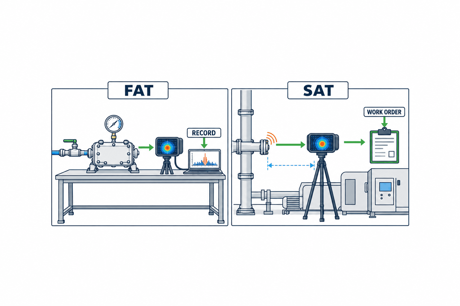
FAT is conducted at the manufacturer or designated testing facility to confirm functionality and performance. It verifies operation according to specifications, presence of accessories, and sample data acquisition capability using standard test fixtures. For acoustic imagers, this involves confirming detection and image recording at specified distances and frequency bands using representative leak fixtures, as well as data export functions. An official report is prepared, clearly stating the serial number and production lot for each unit.
SAT is performed at the actual installation site to verify that the equipment functions as expected under site-specific noise environments, piping layouts, and operating conditions. Standard fixture tests in FAT alone cannot guarantee adaptability to on-site noise, reflections, or distance conditions. SAT evaluates detection capability in real piping, noise separation performance, and reproducibility of data recording and report output in the presence of site personnel. Rights to re-inspection and evidence submission methods are also agreed upon in advance.
Why Uniform Pass/Fail Thresholds Are Not Feasible
The detection performance and estimation values of acoustic imagers are greatly influenced by background noise, detection distance, pipe material and reflection, and device settings (frequency band, sensitivity), all of which vary by site. For example, the official manuals from FLIR and Fluke (FLIR Official Manual, Fluke ii900/ii910 Manual) specify detection frequency ranges and estimation functions, but these are reference values under catalog conditions only. FLIR notes that the 20–30 kHz band is effective for factory noise environments (FLIR Official Guidance), but optimal values will vary with on-site noise and operation.
Therefore, rather than setting uniform criteria such as “signal above XX dB” or “estimation accuracy above YY L/min” for FAT/SAT, it is more practical to create an “acceptance matrix” agreed upon for each site, clearly defining judgment items, methods, and recording formats.
Example Acceptance Matrix
| Test Item | FAT (Factory) | SAT (Site) | Record/Evidence |
|---|---|---|---|
| Operation Check | Detection with standard fixture | Detection in actual piping | Images, videos, log files |
| Frequency Band Setting | Recommended setting | Optimized for site noise | Screenshot of settings |
| Distance/Sensitivity Adjustment | Specified distance/sensitivity | Test at actual installation distance/obstructions | Distance measurement record, site photos |
| Data Output | Sample data output | Export of actual site data | Output files, reports |
| Traceability ID Management | Serial number, test date record | Post-installation ID, location record | Acceptance checklist, layout diagram |
| Right to Re-inspection | Re-test procedures stated | Agreement on site re-inspection | Re-inspection record, agreement |
This matrix is to be pre-confirmed and agreed upon by site personnel, manufacturer, and procurement. For each item, pass/fail criteria and evidence submission methods are documented. For example, data output is confirmed as CSV export of sample data in FAT, and as export of actual site data in SAT. Traceability ID management is always recorded as it provides the basis for responsibility demarcation and warranty response in case of later defects.
Agreement on Acceptance Criteria and On-site Procedures
Acceptance criteria for FAT/SAT should be aligned not only in specifications and contracts but also through pre-meetings between site staff and manufacturer engineers to finalize judgment methods and recording formats. The following workflow is recommended for SAT implementation:
- Site Environment Survey: Confirm noise, piping, and inspection range; plan SAT accordingly.
- Acceptance Matrix Confirmation: Cross-check FAT records and reconfirm SAT items, methods, and criteria.
- On-site Testing: Perform leak detection, data recording, and export under actual operating conditions in the presence of responsible personnel.
- Evidence Submission and Confirmation: Immediately review recorded images/data on-site and decide on acceptance.
- Exercise Right to Re-inspection: If not accepted, follow agreed procedures for re-inspection and recording.
Thus, FAT/SAT acceptance is validated based on site-specific agreements and records, ensuring traceability and reproducibility.
11. Handover of Detection Results to Maintenance Operations
Detection results of compressed air leaks on-site must be reliably handed over to maintenance for appropriate repair and improvement, which is key to energy savings and increased reliability. Beyond merely identifying leaks, it is essential to clarify the workflow from detection to repair completion, ensuring effective execution on the shop floor.
Issuing Work Orders and Handover
After detection, maintenance staff re-checks locations recorded as “candidate points” on site. To prevent miscommunication, location information (system diagram coordinates, area names), detection date/time, responsible person, visual/acoustic images, and a bilingual (Japanese and Thai) ID number are recorded.
Confirmed leak points are “tagged,” with durable tags indicating ID, detection date, planned response date, and responsible person in both Japanese and Thai. Tags serve to link on-site and digital records.
Managing Repair Operations
For tagged leak points, repair tasks are automatically issued in the work order system. Each work order specifies:
- Repair target ID
- Repair content (e.g., retightening fittings, parts replacement)
- List of required parts/tools
- Responsible person and deadline
- Reference photos/diagrams
- Post-repair verification method (whether re-detection is required)
The parts/tools list is described in detail to prevent work interruption, and responsible personnel must confirm in advance.
Post-repair Verification and Recordkeeping
After repair, use the acoustic camera or ultrasonic leak detector again to verify that the leak has been eliminated. Record verification results along with photos/videos, device settings (frequency band, distance, sensitivity), and operating conditions (pressure, number of units running). Consistent with the US DOE’s leak-management guidance, keep repair and reinspection records (US DOE Sourcebook). Since estimated kWh savings vary by site conditions and settings, it is more important to reliably record “presence/absence of leaks” and “recurrence after repair” than to save absolute values.
Closing and Ongoing Management
Once verification is complete, the work order is closed, and photos before/after repair, work details, verification results, responsible person, and date are recorded and managed for access by all relevant parties. This enables easy history tracking and development of recurrence prevention measures in the event of future issues.
We recommend regular route inspections and baseline records to detect recurrence. The ISO 11011:2013 abstract covers system assessment and documentation but does not set patrol intervals.
Multilingual Support and Training
For sites with Japanese and Thai teams, bilingual support should be specified in the operating requirements. Work orders, tags, record formats, procedures, and training materials should be prepared in both languages, ensuring universal understanding. Regular training is also conducted so that all on-site personnel can reliably execute detection, recording, repair, verification, and handover.
12. Frequently Asked Questions
What is the detection range of ultrasonic acoustic cameras?
Detection range varies significantly depending on model specifications, site noise, leak size, and frequency band. For example, the Fluke ii900/ii910 frequency bands are 2–52 kHz and 2–100 kHz, respectively, but these are device specs; actual detection distance depends on leak size, noise, and obstructions (Fluke Official Manual, FLIR Official Guidance). FLIR lists 10–30 kHz as suitable for relatively long-range detection, but the frequency band should be selected according to the device and site conditions. During on-site inspection, it is important to consider detection range and noise components and select the appropriate frequency band. Since estimates fluctuate with distance and settings, always compare with on-site measured values (FLIR User Manual).
Can leak inspection be performed during operation?
Compressed air leak inspections can be performed while equipment is operating. Acoustic cameras and ultrasonic leak detectors allow non-contact visualization, so there is no need to stop the line. However, since background noise affects detection accuracy, it is necessary to temporarily stop or shield noise sources, adjust frequency bands, and prevent false positives through multiple measurements. Repair work must always be performed after equipment shutdown, depressurization, and safety confirmation; never perform disassembly or tightening during operation. Inspection results—including leak location, estimated leak rate, inspection date/time, noise level, and settings—should be recorded and used for repair planning and energy-saving evaluation (US DOE Sourcebook).
How should acoustic cameras and flow meters be used differently?
Acoustic cameras are effective for “locating” leak points and can scan large areas quickly. Flow meters, on the other hand, are suitable for “quantitative evaluation” of total flow or leak rates per piping section. In practice, leaks are pinpointed with an acoustic camera, and the overall leak rate and improvement effects are quantified using flow meters or compressor power measurements (US DOE UMP Chapter 22). Since estimates from acoustic cameras alone can fluctuate under site conditions, reliability is improved by combining with baseline measurements and post-repair re-measurement using flow meters. For details on selection and operation of flow meters, see here.
What should be recorded and checked in RFP, FAT, and SAT?
In the RFP phase, specify detection frequency band, minimum detectable leak rate, detection distance, data recording functions, performance under noisy conditions, maintainability, UI, and other aspects, with an emphasis on practical usability. In FAT, verify performance as specified using simulated leak fixtures and standard piping, and check accuracy by detection distance and band, as well as data storage and export functions. In SAT, confirm under actual factory conditions whether specified leak points can be detected and whether inspection procedures and recording methods are suitable for site operation, with site personnel present. Record items such as inspection date/time, location, settings, detection images, noise level, detection distance, and estimated leak rate. ISO 11011:2013 recommends comprehensive system assessment, documentation, and energy-saving estimation (ISO 11011:2013 official).
What about the price and cost-effectiveness of acoustic cameras?
Introduction cost and cost-effectiveness depend on plant scale, system configuration, leak frequency/inspection frequency, and operator skill levels. Cost-effectiveness is comprehensively calculated based on energy cost reduction through leak detection and repair, reduction in maintenance man-hours, and lower risk of sudden failures or production downtime. The US DOE guide recommends recording leak locations, leak rates, and estimated costs during leak surveys, and quantifying energy savings by re-measurement after repairs (US DOE Sourcebook). Since estimates vary with site conditions, it is essential to compare with on-site data. In the initial phase, sharing among multiple departments, incorporating into regular inspections, and establishing training systems also contribute to improved cost-effectiveness.
13. Summary
An acoustic camera locates candidate leaks. Before procurement, map safe access, actual noise, survey distance and the records your maintenance team needs. Put those site conditions in the RFP. Use an approved positive and negative test fixture plus real production scenes for the PoC. FAT should check the device and data export; SAT should check site detection and handover into repair work orders. Treat displayed leak rate and cost as estimates, and assess energy savings using comparable pre- and post-repair flow and power data (US DOE protocol).
If you are still deciding between purchase, rental and outsourced surveys, or drafting RFP and acceptance criteria for a Thai factory, you can contact TOMAS TECH at that stage.


