



When introducing conductivity monitoring for CIP cleaning in beverage, dairy, and liquid food factories in Thailand, it is essential to decide what constitutes a pass for each product, piping system, and cleaning recipe before assuming that “attaching a sensor can prove the cleaning.” Conductivity provides clues to detect transitions between water, alkaline solution, acid solution, and product, as well as detergent concentration. However, conductivity alone cannot prove the removal of microorganisms or allergens. This article serves as a guide for production, quality, maintenance, and IT personnel at factories with existing CIP systems to consolidate measurement points, judgment logic, records, and acceptance tests into a single set of requirements.
First Decision: Which CIP Cycle Do You Want to Consider “Passed”?
CIP (Cleaning in Place) is a method of circulating cleaning and rinsing liquids through product-contact surfaces such as piping and tanks without disassembling equipment. Only when fluid reaches the equipment, appropriate detergents are used, and required temperature and time are maintained, can the procedure be reproducible. Tetra Pak lists flow, temperature, concentration, and time as key cleaning factors. Therefore, even in conductivity meter projects, the deliverable should not be a single conductivity graph but a cycle record linking these four factors with the target equipment.
In the initial meeting, list “which line, after which product, and with which recipe” will be cleaned. The type and difficulty of soil differ between filling pipes for high-sugar beverages, tanks with residual milk fat, heat exchangers, and mixing valve areas. The quality department gathers hazard analyses and existing validation methods for each product to select the monitoring targets. The new monitoring layer is not intended to replace existing hygiene procedures but to verify in chronological order whether the procedures were executed as designed.
It is important not to confuse the conditions that permit switching to product with those that merely indicate the equipment has moved to the next process, even if both display “CIP complete.” Define operation completion, cleaning condition fulfillment, and quality approval as separate states. For example, when the final rinse conductivity enters a specified range, remains stable for a set time, required flow is maintained, temperature history and valve paths are confirmed, it becomes a “candidate for automatic judgment.” Then, a quality officer reviews exceptions and test results to approve “next batch use allowed,” enabling a two-step approval. Specific thresholds, durations, and approvers are determined by factory procedures and validation.
What Conductivity Reveals and What It Does Not
Conductivity measures the ease of electrical flow through ions in liquid. In CIP, it is used to detect detergent and water boundaries, detergent replenishment status, and changes in return liquid. Endress+Hauser’s food and beverage materials explain that conductivity measurement in CIP return piping and tanks helps manage concentration and phase switching. Because values vary with temperature, measurement temperature and compensation methods must be consistent for comparison. Also, the relationship between concentration and conductivity changes with detergent type and mixing state. Do not apply manufacturers’ general conversion formulas unconditionally to all recipes; verify calibration tables with actual detergent solutions and water quality used.
Conversely, low conductivity only indicates “few ionic detergents in rinse water” and does not alone guarantee surface cleanliness. Non-ionic residues, microorganisms, allergens, cleaning dead zones, and downstream stagnation beyond the sensor require separate verification. EHEDG’s CIP installation guide, which addresses hygienic design and cleaning validation, integrates user requirements, equipment design, management, and verification. 3-A also publishes acceptance practices for CIP piping, equipment installation, and procedures. Clarifying the monitoring value’s role as “process condition evidence” prevents excessive explanations during audits.
Which Phase to Judge
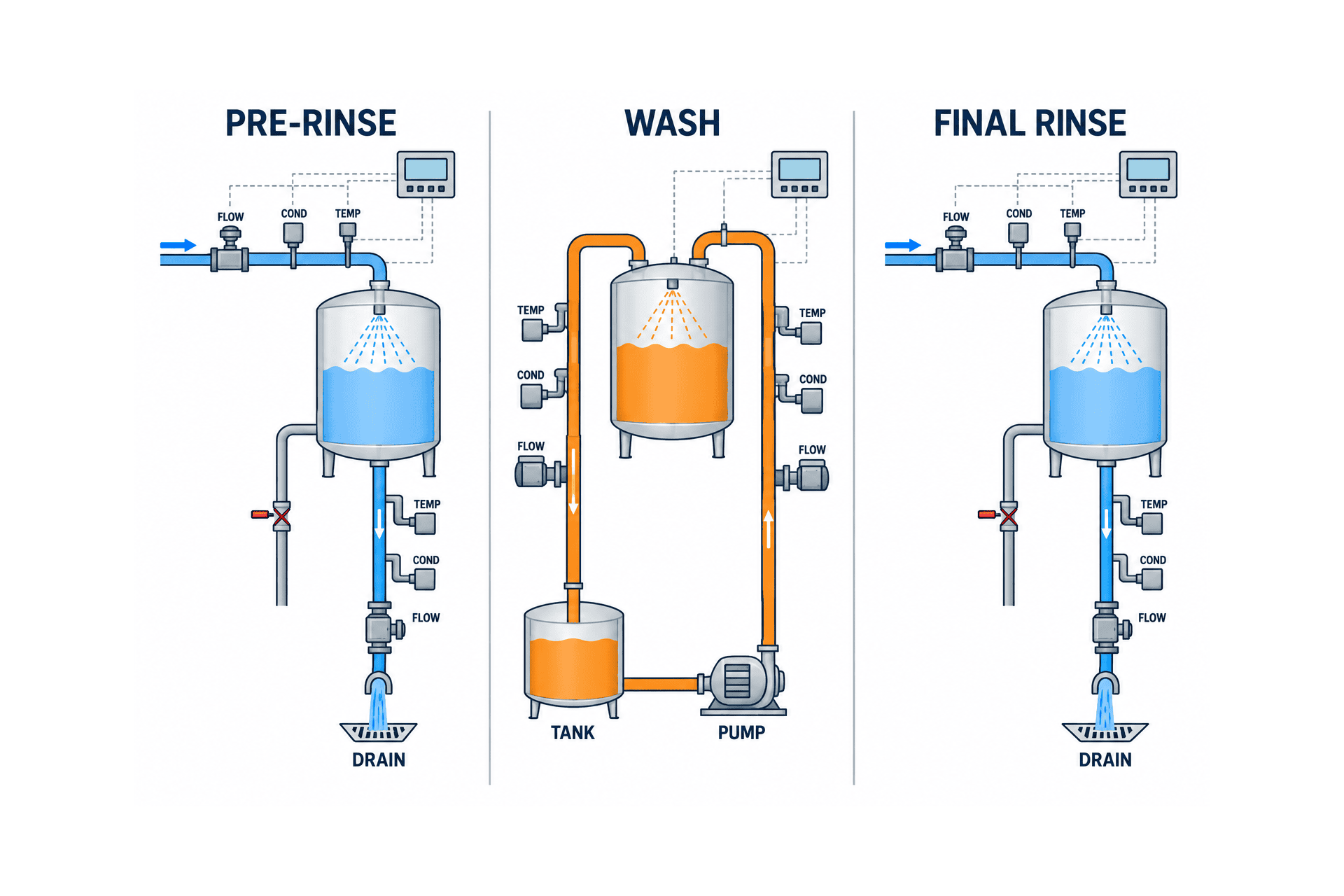
Design separates at least three phases: first, switching from product to preliminary rinse water; second, transition from water to alkaline or acid cleaning solution and maintaining circulation concentration; third, returning from cleaning solution to final rinse water. Without fixing “which piping and valve position the measurement corresponds to” in each phase, the same value can have different meanings. For example, even if the supply side reaches the specified concentration, a delayed return side may indicate the solution has not yet fully reached the entire target equipment. Decide per loop whether both supply and return measurements are necessary.
Because liquids mix at boundaries, switching valves based on a single instantaneous value risks false operations due to noise or bubbles. Write hysteresis separating upper and lower limits, continuous fulfillment over a set time, AND conditions with flow confirmation, and safe-side actions on sensor faults into the PLC specification. These are design proposals, not universal thresholds. Delaying switching increases detergent loss; switching early risks rinse or recovery quality. Confirm boundary waveforms with actual liquids during FAT and SAT to finalize settings.
Measurement Points Selected Not Only at Tanks but Also Supply, Return, and Drain Paths
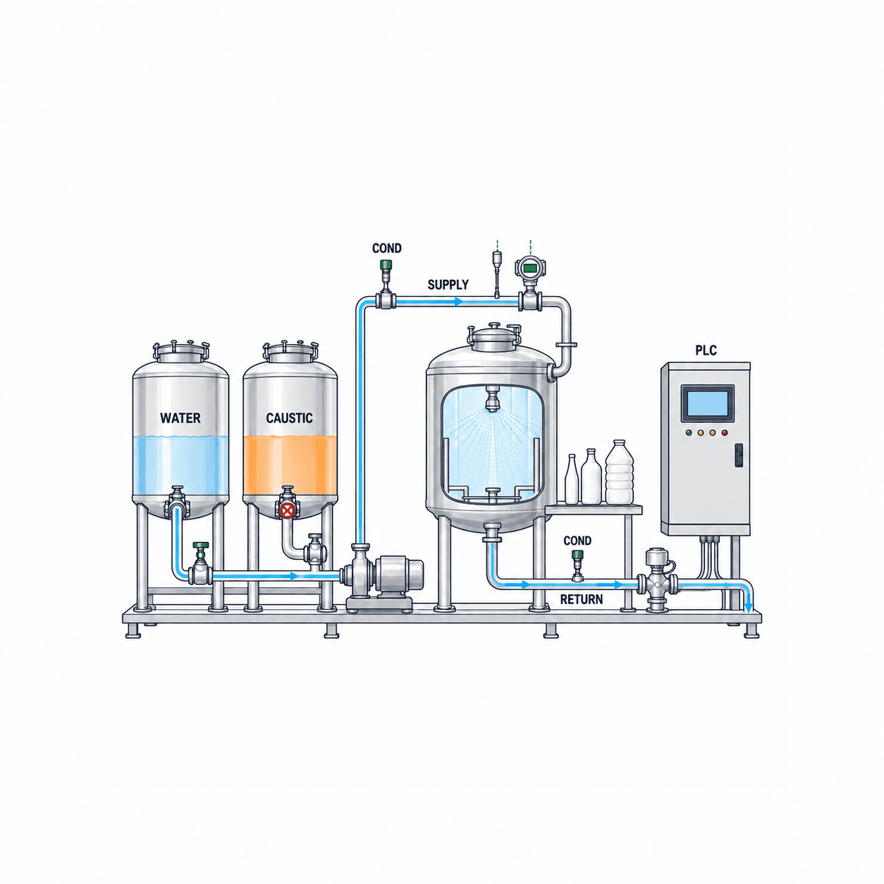
When adding conductivity meters to existing CIP, overlay CIP tanks, pumps, heat exchangers, supply headers, each target equipment, return headers, recovery valves, and drain valves on the P&ID. The location depends on the question to be answered. For detergent adjustment, measure at the tank; to verify liquid sent to the target, measure supply; to observe the actual return phase, measure return; to reduce contamination into drainage, measure before the switching valve. One return sensor may not represent all loops. At branch convergence points, valve states must identify which equipment’s return is measured.
Sensors become part of the equipment that keeps the cleaning target hygienic. Selection criteria include not only measurement accuracy but also wetted materials, connections, seals, drainage, ease of disassembly and inspection, and compatibility with temperature, pressure, and detergents. Endress+Hauser’s hygienic inductive sensors list CIP phase separation, concentration management, and product monitoring as applications and offer various process connections. This is not a mandatory product adoption. Check each candidate’s compatibility with onsite pipe diameters, flow rates, cleaning agents, and existing connections. Hygienic design personnel verify that welds or fittings do not create new stagnation points by reviewing both drawings and actual equipment.
Include temperature compensation presence, reference temperature, output units, and calibration procedures in the same specification. If the PLC receives ambiguous values—raw conductivity or temperature-compensated—the screen may appear normal but judgment bases collapse. Decide which standard liquids—reference solution, actual detergent, or factory supply water—will be used for validation during sensor post-cleaning inspection, and maintain replacement history and calibration records. Interlocks are also necessary to prevent faults such as disconnection, fixed values, communication loss, out-of-range, or unexpected rapid changes from being interpreted as “cleaning OK.”
Record Flow Rate, Temperature, Time, and Conductivity with the Same Clock
Even if conductivity is appropriate, insufficient flow rate may prevent thorough cleaning of some piping sections. If the temperature is lower than the set value, the chemical’s effectiveness conditions change, and even if phase switching is correct, insufficient holding time means the recipe is not met. Tetra Pak’s CIP unit documentation shows a configuration that automatically controls cleaning time, detergent temperature, flow rate, and concentration. Rather than directly quoting this as your own equipment’s acceptance criteria, use it as a reference for the requirement that “all four records are collected.”
In data collection, avoid the assumption that saving PLC scan values every second is always sufficient. Define the cycle that reveals short changes at phase switching, the intervals lost due to communication interruptions, and the granularity of aggregated values sent to MES. For example, the monitoring screen may display continuous waveforms, while batch records save start and end times for each phase, minimum flow rate, duration within minimum or allowable temperature ranges, duration within conductivity bands, alarms, and manual operations. These example items and aggregation methods should be adjusted according to each equipment’s validation. The retention period for raw data and correction history is also determined by quality record management rules.
Time synchronization is a subtle but critical point. If the clocks of the CIP unit, PLC, SCADA, and MES drift, it becomes impossible to reproduce whether “manufacturing started after cleaning finished.” Decide on the standard time and synchronization method within the Thailand factory, behavior after power restoration, and record retention during offline periods. Separate sensor-to-PLC as on-site control and MES as the inquiry and approval layer, so that network failures do not shift hygienic stop decisions beyond the cloud.
Verify Setpoints on Actual Liquids and Equipment Instead of Simply “Copying”
First, organize existing CIP procedures, chemical manufacturer usage conditions, past cleaning failures, swab tests, and residue inspections. Next, measure the relationship between conductivity and concentration at various temperatures using supply water and actual detergents, and collect waveform data of good product cycles on the actual target loop. Observe seasonal and supply water quality changes, deterioration of recovered liquids, and conductivity fluctuations due to product residues. Before horizontally applying a single “CIP threshold” to all products and piping, define the applicable range for each recipe and equipment combination.
Dividing judgment criteria into four layers makes operation easier. The first layer is instrument integrity—are temperature signals and communications normal? The second layer is the path—are the necessary valves in the correct positions, and are pumps and flow established? The third layer is process conditions for each phase—do conductivity, temperature, flow rate, and duration meet the recipe? The fourth layer is quality approval—have exceptions, tests, and product changeover risks been confirmed? When any layer is missing, do not simply show a “red light”; instead, define work instructions for next steps such as re-rinsing, re-cleaning, maintenance calls, or quality holds.
As one example, the final rinse completion condition can be expressed as: “The return-side temperature-compensated conductivity enters the water quality range verified at the factory, remains continuously for the specified time or longer, flow is established, and the target loop’s valve states are correct.” However, specific values for water quality range and time cannot be determined from this document alone, as they vary by food type, chemicals, piping volume and shape, and validation tests. Define bypass authority and manual approvals during abnormalities, including who records reasons and which subsequent tests are required. If manual resets without records become routine, improvement points for equipment become invisible.
Hygienic Design and On-Site Operation in Thailand Factories
In Thai food factories, applicable food categories, domestic sales or export, and customer audit conditions differ by factory. Thai Ministry of Public Health Notification No. 420 on food manufacturing, listed in the Thai FDA GMP resources, provides a GMP framework reference for manufacturing methods, equipment, and storage. However, this article does not claim that the notification mandates specific conductivity values, sampling intervals, or MES functions. Interpretation of applicable requirements should be confirmed by the factory’s quality assurance department and responsible experts, and equipment setpoints decided based on equipment validation.
On-site, attention is needed for chemical handling, high-temperature areas during cleaning, incorrect valve operations, and recovery after maintenance. Confirm that conductivity meter installation does not obstruct worker cleaning or inspection routes, and that wiring boxes and cleaning hoses do not interfere. Stabilizing phase judgment and reducing incorrect switching may be more effective than increasing chemical dosing control, but verify effects with on-site measurements. Compare water volume, chemical volume, wastewater volume, cleaning wait time, and re-cleaning frequency under the same conditions before and after introduction, and do not repurpose these figures as general sales data.
Quality personnel require screens to investigate daily exceptions, maintenance personnel want to detect instrument failure signs, and production personnel want to judge batch start readiness at a glance. Do not consolidate these three roles’ needs into one huge graph; instead, provide separate views for cycle pass/fail, cause codes, waveforms, instrument status, and approval history. Unify terminology used on-site, including Thai language. Also document in work standards which conditions correspond to screen statuses such as “Cleaning Complete,” “Usable,” and “On Hold.”
What to Pass to MES for Batch Traceability
How to Design the Granularity of Records and Correction History
A configuration that sends only “pass” or “fail” per cycle to the MES is simple, but it may be insufficient for later root cause investigations. For example, if the final rinse time is prolonged, it is impossible to distinguish whether the supply water changed, the detergent recovery valve was delayed, or the sensor response slowed down. It is practical to retain continuous values and events in the PLC, while passing summaries for each process phase and identifiers referencing the original waveform to the MES. The frequency of data storage should be determined based on the speed of phase transitions, communication capacity, and the necessity for audits and root cause analysis. Do not aim to store all tags indefinitely at the shortest cycle.
Manually entered reason codes, hold release comments, and re-cleaning instructions should be linked to the same cycle ID as the sensor values. When correcting recording errors, do not erase the original values; instead, track before and after corrections, reasons, executors, and timestamps. Distinguish between the “current judgment” displayed on the screen and the “judgment at the time” made by the logic in effect then. Designing the system so that past CIP cycles automatically change to pass simply because new thresholds are registered later complicates quality explanations. Retention periods and the need for electronic signatures should be individually determined according to the laws applicable to the factory, customer requirements, and internal quality procedures.
Clearly Define Boundaries with Manufacturing Batches
When a single CIP cycle cleans multiple pieces of equipment, record not only the overall pass/fail of the cycle but also the completion status for each target loop. Conversely, when multiple CIP processes are run consecutively on a single piece of equipment, define at which process completion point manufacturing is permitted. The cycle ID linked to the batch should be a definitive one with equipment ID, route ID, timestamp, and recipe version—not an ambiguous string like “the last cleaning immediately before.” If approval is incomplete at the start of manufacturing, design whether the MES only issues a warning or blocks the manufacturing order, based on the safety and operation of existing equipment.
Reprocessing and interrupted production are also anticipated. If the equipment is opened for inspection mid-batch and then closed again, the previous CIP approval cannot necessarily be reused as is. Record any interventions on product contact surfaces and prepare a flow where quality determines the need for re-cleaning or re-verification. Even if the equipment is the same, if allergen conditions change due to product switching, the required verification may differ. Such judgments are based on the factory’s hazard analysis and hygiene procedures, not on conductivity calculations.
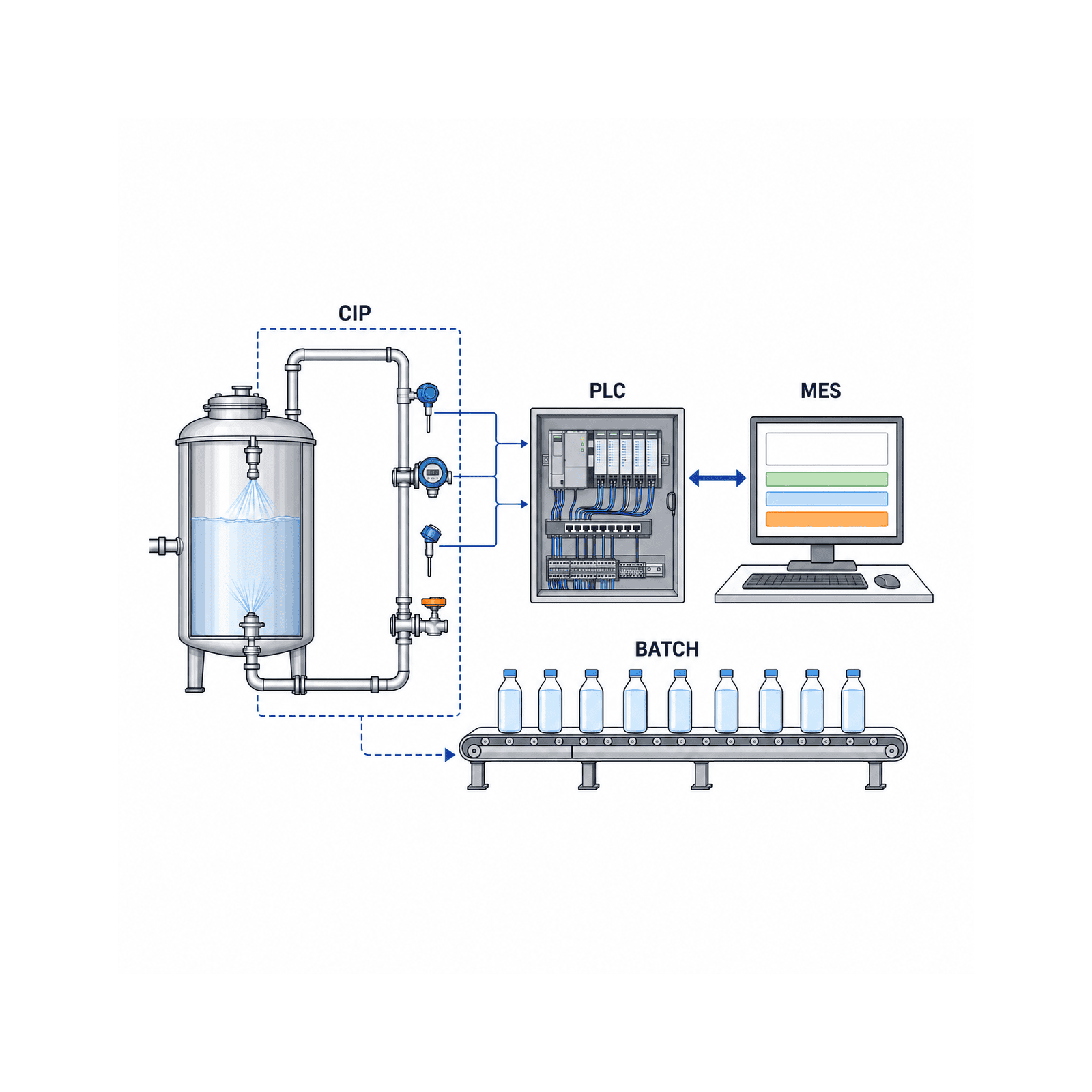
The value of CIP monitoring lies more in its connection to manufacturing batches than in standalone dashboards. Link equipment ID, target loop, CIP recipe version, cycle ID, the immediately preceding product or batch, and the next product batch processed. Also enable referencing of start and end times for each phase, the status of conductivity, temperature, and flow rate validation, alarms, manual interventions, approvers, and sensor calibration status. This allows quality inquiries to trace “which cleaning was completed under what conditions before producing this batch.” The concept of organizing lot genealogy from raw materials to shipment is also summarized in our Food Factory Traceability System Implementation Guide.
The boundary for MES integration should also be clear. One approach is for the PLC to control valves, pumps, and interlocks, while the MES handles cycle ID issuance, recipe version management, history referencing, and approvals. Before easily rewriting control logic on existing equipment, establish a stage to verify data integrity through read-only integration. If data loss occurs, define unique IDs and retransmission rules to prevent duplicate registration of the same cycle upon message resend. Include in the BCP how the PLC retains records and who authorizes production when the MES is down.
When connecting CIP to an existing production management system, first align differences in equipment lists and product master names, recipe revision dates, and lot finalization timing. Re-evaluating cycles cleaned with pre-revision recipes using post-revision settings changes the meaning of records. Fix the recipe version and judgment logic version at the time of evaluation to the cycle. For an overall view connecting production, inventory, and quality data, see also the Food Factory Production Management System Selection Guide.
Write Acceptance Criteria in the RFP Rather Than Just Instrument Model Numbers
Prepare On-Site Information to Provide to Vendors
If the P&ID is outdated at the proposal request stage, first mark discrepancies against the actual equipment in red. Confirm whether there is sufficient straight pipe length near measurement points, space to remove sensors, pipe orientation prone to air pockets, and whether cleaning temperatures and pressures differ from normal production. Without specifying the types and actual concentrations of chemicals, fluctuations in supply water, and methods for reusing recovered liquids, vendors cannot select appropriate ranges or materials. A list of I/O for existing valves and pumps, PLC model, communication specifications, time synchronization method, MES connection points, and network change request procedures also affect quotation accuracy.
Construction conditions should be treated as technical conditions. In food factories, there are limited windows to stop piping, and time is required for welding, cleaning, leak checks, and hygienic revalidation. If commissioning is squeezed just before production starts, there is no margin to calibrate values or fix issues found during SAT. Align construction schedules with production plans, and include in the RFP whether alternative lines are available, chemical procurement, and quality personnel attendance. It is important not to compare quotations solely by price between those that include such conditions and those that do not.
Scoring Sheet for Comparing Proposals
Dividing the comparison sheet into six categories—“Hygienic Design,” “Measurement Validity,” “Control and Safety,” “Data and Traceability,” “Operation and Maintenance,” and “Implementation Plan”—makes it easier for related departments to discuss. Hygienic design covers wetted materials and fittings, drainage, and inspection methods. Measurement covers compatibility with actual liquids, temperature compensation, calibration, and response time. Control covers prevention of incorrect switching and behavior on failure. Data covers cycle ID, recipe version, waveform, and correction history. Operation covers Thai-language procedures, spare parts, and maintenance contacts. Implementation plan covers downtime, FAT/SAT, training, and handover. Weighting of scores is determined by the factory’s hazard analysis and constraints of existing equipment; do not decide pass/fail based solely on manufacturer name.
If a proposal states “guaranteed X% reduction in cleaning agent usage,” verify the baseline values and comparison conditions. Designs that recover water or chemicals can be beneficial, but if premature switching poses a food safety risk, reduction effects cannot be prioritized. If the initial implementation goal is to establish quality evidence, reduction should be a secondary evaluation item. Clearly stating the primary success criteria prevents inconsistent decisions during commissioning.
The request for proposal to vendors should include the factory’s objectives, existing P&ID, target loops, target products, cleaning recipes, current recording media, chemicals and water quality, operating environment, and network configuration. Then, ask the proposer to specify measurement points, wetted materials, hygienic connections, temperature compensation, calibration and replacement, PLC signals, MES data models, operation screens, exception handling, training, and spare parts. “Complete conductivity visualization system” alone is insufficient for comparison.
Quotation comparison items should include not only initial costs but also piping downtime, scope of changes to existing control, calibration confirmation with chemical manufacturers, periodic calibration workload, spare sensors, annual maintenance, data storage, and failure recovery. There may be possibilities to use multivariate measurement from existing flowmeters without additional sensors. Endress+Hauser has published beverage factory case studies combining flowmeter and conductivity measurement. However, confirm separately whether product specifications and measurement ranges fit all phases of your process. Comparison should be based on “total cost to reproduce one CIP cycle,” not “instrument unit price.”
An example of a concrete requirement statement is as follows: “For target loop A, determine start and end of pre-rinse, alkaline wash, and final rinse; save conductivity, temperature, flow, valve status, and recipe version with cycle ID. Prohibit automatic pass on sensor failure or missing timestamp; retain reason codes and operation history. Quality personnel can view exception lists and waveforms before starting the next batch.” This is a design example, not a specification to use as-is. Revise to reflect risks of individual piping and food products.
Failure Scenarios to Confirm in FAT and SAT
Transfer Test Records to Operation
FAT test records should include simulated input/output values, expected state transitions, actual logs, evaluators, and unresolved issues. In tests changing conductivity from high to low, add noise crossing boundaries multiple times. Confirm whether switching occurs immediately when conditions are met, whether continuous fulfillment is required, and whether timers reset if values revert. Check that temperature compensation and raw values are not swapped, PLC units match screen units, and alarm disable histories are recorded. Attaching actual records is more useful later than just checkboxes on documents.
In SAT, do not approve only completion of piping work. Measure delays until liquid sent to target equipment returns, moments when recovery and drainage switch, different flow ranges per equipment, and changes in detergent concentration. Evaluate cleaning validity tests according to existing quality plans; do not substitute solely with conductivity values. Record chemical lot used, supply water condition, and calibration status of equipment and sensors. After testing, agree on who and when will close unresolved items and which items are mandatory before operation start.
It is advisable to establish a “stabilization period” after operation start during which exceptions from all cycles are reviewed daily. If false alarms are frequent, investigate causes such as foam, empty piping, wiring, temperature compensation, valve information, and recipe selection before relaxing thresholds. Only reflect revisions approved by quality department in production, and distinguish cycles before and after revision. Handover to maintenance should include calibration cycle determination, post-replacement verification, spare part models, and procedures for sensor failure.
In FAT (Factory Acceptance Test), use simulators or test liquids to input conductivity up/down, temperature anomalies, zero flow, valve position mismatches, communication interruptions, sensor failures, and power recovery; verify PLC, screen, and history behave as intended. Do not rely only on screen colors; record which input conditions transition to which states and why automatic pass was not granted. Confirm that users without approval authority cannot override exceptions and that timestamps and revision versions remain.
In SAT (Site Acceptance Test), use actual piping and liquids to confirm supply-return time differences, mixing zones, time to stabilize final rinse, and operation of recovery and drainage valves. Confirm cleaning reaches the ends of target piping by combining with cleaning validation methods adopted on-site. 3-A documentation introduces concepts for verifying spray device coverage in tanks. Even if conductivity waveforms look clean, this does not mean blind spots are eliminated. SAT pass/fail is judged by pre-agreed test methods and acceptance criteria.
Acceptance tests include not only normal cycles but also intentionally failed cycles. Reproduce detergent shortage, supply water fluctuations, low flow, incorrect recipe selection, manual valve reset omissions, MES disconnections, and immediately after sensor replacement; confirm hold and recovery flows. Since not all can be safely reproduced on actual equipment, divide into FAT simulation, SAT safe testing, and operation procedure confirmation. Test records should include executor, recipe version used, input waveforms, judgment, corrective actions, and retest results.
Implementation Sequence: Start with One System and Establish Judgment Criteria First
Criteria for Selecting the Initial Target
When selecting the target loop, it is advisable not to decide solely based on “locations where it is easy to install conductivity meters.” Confirm whether frequent product changes and missing records are delaying quality judgments, whether manual decisions remain in switching between cleaning agents and water, whether supply and return paths can be traced on the P&ID, and whether hygienic tests can be conducted on-site. The first demonstration should be important enough to measure the effect but limited to a system that can be tested without impacting the entire facility. Choosing a complex mixing pipe first may consume time just identifying the meaning of sensor values.
During the initial survey, observe how operators record the start of cleaning and who confirms its completion. When transitioning to automatic recording, it is important not to discard exceptions or equipment condition knowledge previously confirmed by personnel. For example, if experienced operators judge valve sticking or delayed drainage from a specific tank based on experience, include those events as test items and alarm candidates. At the same time, do not convert all on-site judgments into “automatic OK” but retain a place to record the decision-maker and rationale.
Review Cycle After Implementation
Even after implementation, products, detergents, water quality, piping, and sensors will change. At a minimum, a system is needed to re-evaluate set values and their validity whenever changes occur. During periodic reviews, list the number of alarms, reasons for manual overrides, re-cleaning rates, calibration deviations, sensor replacements, and quality test results. Do not conclude “no problem” by only observing normal value trends; also verify whether the absence of detected abnormalities is due to sensor malfunction. Reflect review results in the next recipe revision and maintenance plan.
When expanding to multiple lines, reuse the basic data items and screen layouts decided on the first line, while performing threshold setting and hygienic validation for each loop. Unifying naming conventions for line names, equipment IDs, recipe IDs, and cycle IDs facilitates quality inquiries and MES integration. However, differences in piping length, tank shape, and cleaning liquid return flow mean waveforms and arrival times will not be identical. Managing “templates” separately from “equipment-specific validity” reduces rework during expansion.
The first stage is understanding the current situation. Collect cleaning recipes, P&IDs, past hygienic tests, chemical specifications, required cleaning times, and reasons for quality holds, then narrow the target to a single loop. The second stage is observation: without changing existing controls, record conductivity, temperature, and flow rate on supply and return sides, and compare passing and failing cycles. The third stage is judgment design, where quality assurance, production, and maintenance approve thresholds and exception handling. The fourth stage gradually introduces PLC automatic judgment and MES integration. Finally, align FAT/SAT records and operator training before moving to actual operation.
It is also important not to leave responsibilities ambiguous. Quality handles hygienic judgment criteria and validation tests; production manages recipes and manual operations; maintenance is responsible for instruments and piping; IT/OT manages data and access rights; vendors handle design, testing, and handover. Request detergent manufacturers to confirm temperature and concentration conditions. In change management meetings, decide which changes—new products, chemical changes, piping modifications, sensor replacements, PLC updates—require revalidation. Do not treat the system as “complete” without appointing an operational manager after implementation.
Effect measurement should be conducted for both manufacturing quality and resource usage. Compare before and after implementation metrics such as time to detect exceptions, record search time for quality inquiries, re-cleaning rates, CIP cycle times, water usage during product changeover, and chemical replenishment amounts. Simple comparisons are not possible if product items or seasons differ. Evaluate after recording comparison periods, product composition, cleaning recipes, and equipment conditions. Rather than promising a uniform reduction rate by conductivity monitoring, first create operational records that can explain causes.
Frequently Asked Questions
Can Microbial Testing Be Omitted by Using Conductivity Monitoring in CIP Cleaning?
Omission cannot be decided based solely on conductivity. Conductivity mainly indicates changes in ionic components and process conditions. Methods for confirming microorganisms, allergens, residues, etc., according to products and hazards, follow the quality department’s validation. Conductivity records are useful as supplementary evidence to demonstrate that the prescribed cleaning recipe was executed.
Should Conductivity Sensors Be Installed on the Supply Side or Return Side of CIP?
It depends on the purpose. The supply side shows chemical concentration and delivery conditions, while the return side better reflects the phase of liquid passing through the target equipment. For mixing pipes, valve information is needed to identify the return source. Draw the judgment target and liquid flow path on the P&ID and select necessary points.
What Should Conductivity Set Values and Final Rinse Completion Values Be Based On?
There is no universal value. Decide for each factory recipe based on the chemicals used, temperature compensation, supply water conductivity, product residues, target piping, and hygienic validation results. Record the rationale for set values, reviser, and effective date, and review when chemicals or equipment change.
Can We Start Only with Existing CIP and MES Integration?
If the existing PLC has the necessary signals and cycle IDs, you can start with read-only historical data integration. If required signals are missing, estimate the scope of sensor additions or control modifications. MES should receive not only pass/fail of cleaning but also which batch preceded the cycle, which recipe version was used, and who approved exceptions.
What Should Be Prioritized in RFP and FAT/SAT?
More than normal operation screens, ensure that automatic pass is stopped during abnormalities and reasons can be traced later. Include sensor failure, low flow, communication loss, manual intervention, and time discrepancies in test sheets. On-site, separately verify phase switching of actual liquids and cleaning validity of target equipment.
Summary
Conductivity monitoring in CIP cleaning is a powerful method to visualize phases of cleaning agents and water, concentration management, and rinse changes. Success depends not on the mere presence of sensors but on which piping and phase are measured, how flow, temperature, time, and valve states are combined, and which validation results determine set values. In Thai food and beverage factories, consolidating hygienic design, on-site operations, quality approvals, and MES batch history into a single CIP cycle ID connects daily decisions with later explanations.
If you are considering organizing measurement points for existing CIP or combining conductivity monitoring with MES history in an RFP, please share your current piping diagrams and operational challenges via Contact TOMAS TECH. We can assist with consultations before finalizing specifications.
References
- EHEDG, Hygienic Design Requirements for CIP Installations, Guideline 50
- 3-A Sanitary Standards, Installation and CIP of Processing Equipment and Hygienic Pipelines
- 3-A Sanitary Standards, Riboflavin testing for CIP coverage
- Tetra Pak, Cleaning of Processing Equipments
- Tetra Pak, CIP unit P
- Endress+Hauser, Food & Beverage Industry Portfolio, CIP section
- Endress+Hauser, Multi-parameter measurement in CIP cleaning systems
- Thai Food and Drug Administration, GMP resources


