



A PCB AXI X-ray inspection AI implementation should begin with a quality question, not an advertised AI accuracy figure. Which hidden joints matter, what defects must be detected, what evidence makes a board pass or fail, and what happens to an uncertain result? Optical AOI cannot fully observe joints beneath some packages, including BGAs. AXI can reveal internal structures with X-rays, but obtaining an image does not by itself prove reliable defect classification. This guide takes a Thailand SMT line through scope, imaging method, proof of concept, procurement, acceptance, and operation.
This is a practical procurement guide. It is not a radiation safety design or a declaration of compliance. Confirm installation, use, shielding, interlocks, maintenance and local legal requirements with the equipment supplier and qualified local specialists.
Limit the AXI business case to joints that need X-ray evidence
AOI uses visible light to examine observable assembly features: component presence, orientation, placement, and visible solder. AXI uses X-ray transmission to examine structures hidden under a component or within an assembly. One does not replace the other in every case. They measure different physical signals, operate at different speeds, and incur different costs. Start by mapping defects already covered by AOI and the remaining joints whose required evidence is inaccessible to visible light.
OMRON’s CT AXI technology paper discusses BGAs and fillet-less components as examples whose joints are hard to inspect optically. It also compares 2D X-ray, tomosynthesis and CT imaging. Its performance claims concern the device and conditions studied. They should not be transplanted to a plant’s own board stack, copper density, double-sided assembly or product mix without testing.
Write a procurement objective as a verifiable sentence: “For BGA joints on product A, identify the agreed bridge and void conditions and record board ID, joint location, image, recipe and disposition.” This is more useful than “buy AI X-ray inspection.” A demonstration image cannot satisfy the former without a result tied to real boards and agreed defects.
Build a defect and limitation register
“Inspect BGAs” is too broad. List bridges, opens, voids, solder amount, misalignment, tilt and foreign material only where they are relevant to a specific package and product. Distinguish what the image measures from what another test establishes. X-ray appearance alone does not guarantee electrical continuity, bond strength or lifetime reliability. There is no universal void percentage that automatically proves every joint acceptable; product design, materials and customer criteria matter.
For each joint or region, record component type, board side, location, defect class, clear pass sample, boundary sample, unresolved sample, agreed disposition and final decision owner. Keep product revision, board ID, image, recipe version and timestamp with the judgement. If there are too few credible boundary samples, make collecting them and agreeing the truth criteria part of the PoC. Do not call a prototype recipe “accepted for mass production” while the limits remain undecided.
Divide responsibilities among AOI, AXI and electrical tests
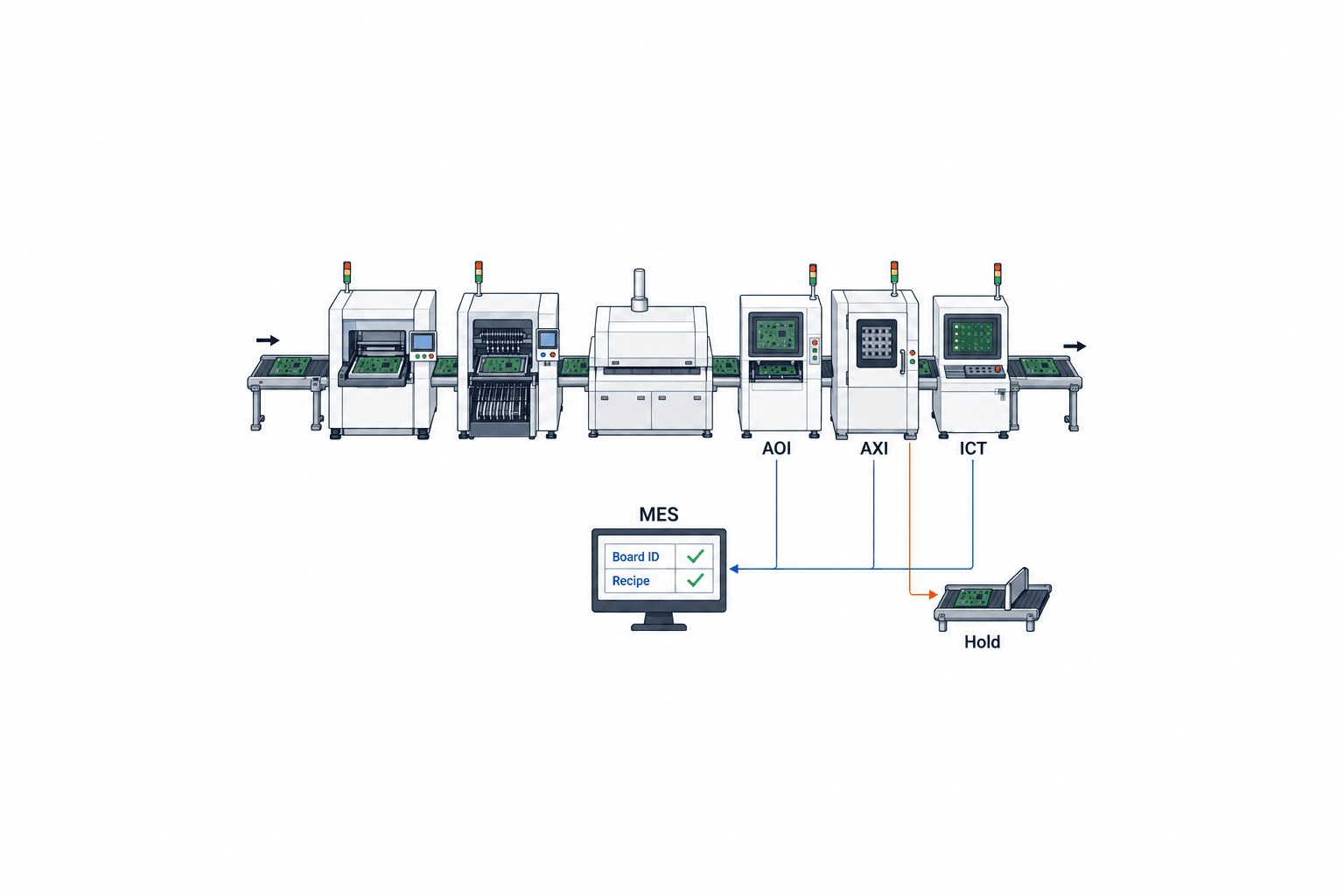
AOI can catch visible assembly issues early. AXI is useful for covered joints and structural overlap. ICT and functional testing address electrical behaviour. These methods have different failure coverage; quality assurance must show which failure mode each method can or cannot address. Our visible solder joint AOI guide focuses on optically observable joints. This article focuses on hidden joints.
| Quality question | Candidate evidence | Remaining AXI decision |
|---|---|---|
| Presence, polarity or visible placement error | AOI and placement logs | Would X-ray add a decision that matters? |
| Covered BGA joint or overlapping solder structure | 2D, angled AXI, or CT | Can the overlap be separated sufficiently? |
| Electrical connection and function | ICT or functional test | How are conflicting results investigated? |
| Strength or long-term reliability | Design validation and suitable analysis | Which claims cannot be inferred from the image? |
Map these checks to the process flow. If an AOI pass is treated as proof that unseen BGA balls are sound, a coverage gap remains. Conversely, making AXI classify every easy optical feature may waste machine time and human review. Define who holds the board when results disagree and who has final release authority.
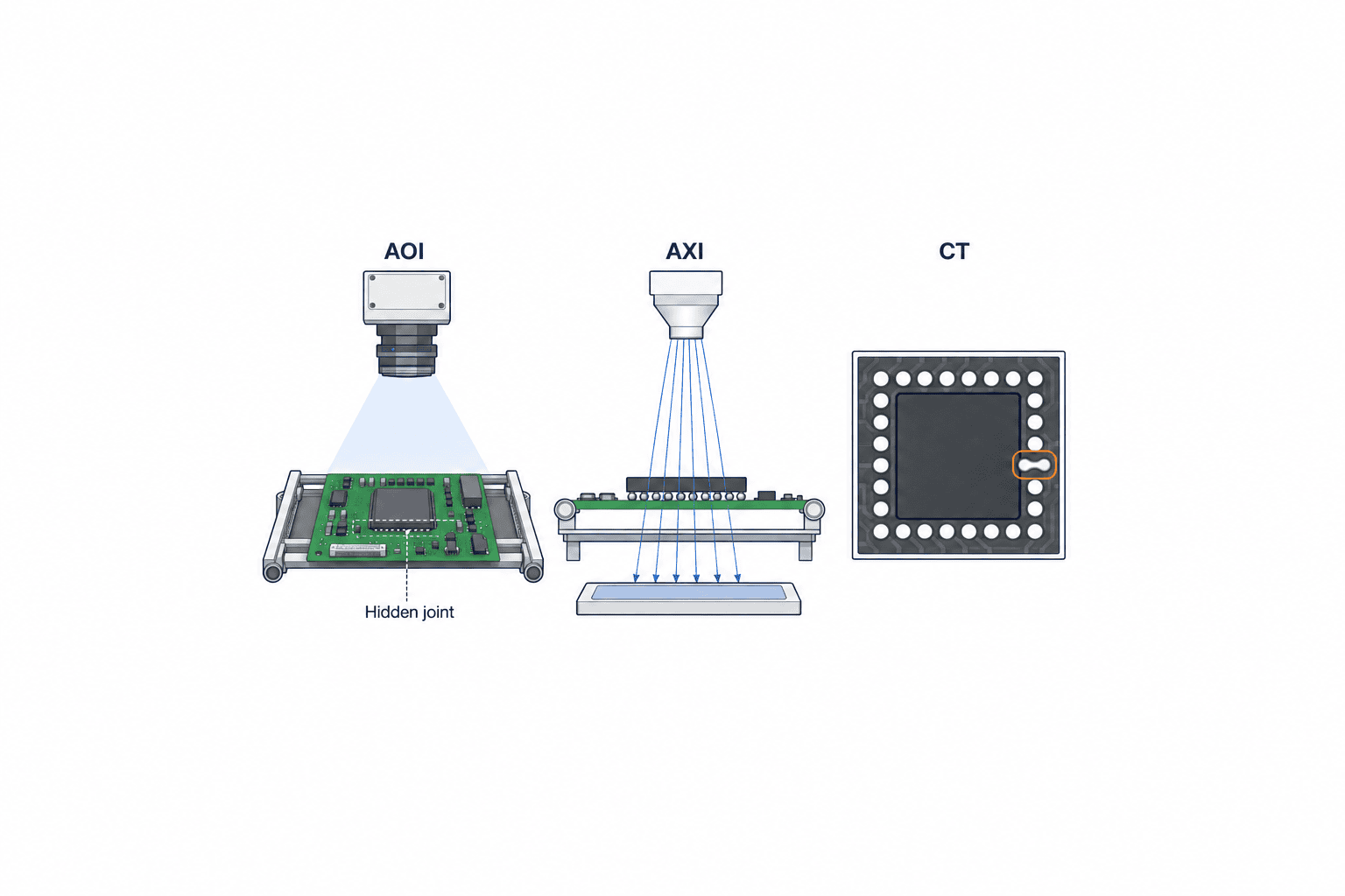
Compare 2D X-ray, angled imaging and CT on the actual product
A 2D projection superimposes structures along the beam path. It may be fast and adequate for a relatively simple stack, but traces, copper planes and components on both sides can obscure a joint. Angled views and reconstruction can help distinguish some overlaps. CT provides sectional information and can separate concealed structures, subject to image quality and throughput constraints. “CT is more precise” is not enough to select a production recipe.
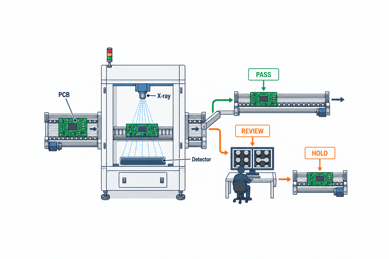
OMRON’s paper on continuous movement between CT fields of view illustrates that throughput depends on motion and image acquisition, as well as analysis. Board transfer, alignment, field movement, projections, reconstruction, AI inference, review and unloading all consume time. Compare total board occupancy at the contracted inspection scope, not only inference time per image or a headline machine specification.
Use the same difficult boards for each method: densest surrounding copper, small joints, both-sided assemblies, maximum panel size, permissible warp, repair and product variants. Record every non-evaluable location with a reason and an alternative inspection path. For mixed production, measure recipe changeovers, retries, re-imaging and queue delays. A buffer can absorb variation for a while; it cannot repair a sustained shortfall in inspection capacity. Review capacity is another bottleneck: boards may wait for an engineer even when the machine has moved on.
Define exactly what the “AI” decides
An AXI supplier may use AI to detect candidate regions, classify defects, estimate a measurement, assign an anomaly score or prioritise human review. Ask for the boundary among fixed image-processing rules, statistical thresholds, learned models and human decisions. Is an AI output the final PASS/FAIL, or an advisory flag? The answer changes the acceptance test and accountability.
Training data should cover normal product, lot, machine and imaging variation as well as confirmed defects. Keep evaluation examples separate from training and threshold tuning. Randomly dividing images by board ID may still put near-identical images from one panel or lot in both sets. Check the links among panel, lot, date, machine and repeat imaging when splitting data. If a rare defect has little evidence, report the uncertainty instead of quoting a single overall accuracy percentage.
Measure misses and false rejects separately
A miss releases a defect; a false reject consumes investigation and may hold good output. Their costs and acceptable limits depend on the product and customer. Define defect-specific denominators, the method of establishing ground truth, sample counts, treatment of uncertain cases and repeats before seeing the results. A second person interpreting the same X-ray is not necessarily independent ground truth. Depending on the defect, electrical testing, sectioning, destructive analysis, process history and customer limit samples may contribute. Keep an unresolved case unresolved until evidence supports a disposition.
Manage a model update as a controlled recipe change. Record model and training-set versions, thresholds, applicable products, approval, comparison on a fixed evaluation set and a route back to the previous version. Lower false rejects on one class can conceal new misses on another. Automatic retraining from recent shop-floor images needs confirmation of labels and a release process, not just a nightly job.
Run a PoC as an acceptance experiment
A supplier demonstration with attractive images is not a procurement trial. A PoC protocol needs a defined product, defect list, regions, quantities, imaging settings, truth method, blind evaluation, metrics and rules for non-evaluable images. Collect naturally occurring defects and good boundary cases where possible; manufactured defects alone need not reflect production. Split material into a set the supplier may use to tune the recipe and a holdout set reserved for the formal test. Any changes during evaluation must be logged and retested on independent examples.
Include the most difficult boards rather than only an average good board: dense copper, both-sided overlap, minimum relevant joint, panel variation, allowed warp, repaired boards and product revision differences. Give each image a stable ID. Keep pre-supplier truth, supplier judgement and independent adjudication separate. If product confidentiality prevents shipping boards, agree on a site-based trial or an acceptable data handling arrangement before asking for quotes.
Evaluate three dimensions. Technical: defect-specific misses, false rejects, image quality and blind spots. Operational: cycle time, review effort, retry behaviour and recovery. Safety: supplier evidence for shielding, access interlocks, installation and service; obtain local specialist advice on applicable requirements. This article cannot substitute for that assessment.
Put the actual scope in the AXI RFP
“AXI with AI” gives vendors too much freedom to quote different tasks. Fix product and defect scope first. Then ask each vendor to state imaging method, judgement process, line interface, data output, support and acceptance evidence. The broader relationship between inspection results and production analysis is covered in our quality inspection data article.
| RFP line | Required answer | Proof |
|---|---|---|
| Boards | Size, thickness, warp, panel, weight, sides and direction | Transport actual boards |
| Target joints | Package, location, overlap and defect classes | Match the defect register |
| Imaging | 2D, angled or CT per region, with reason | Compare identical samples |
| Decision | Rule, AI, reviewer, uncertain case and repeat imaging | Blind evaluation |
| Capacity | Occupancy per product, mixed flow and reviews | Timestamped continuous run |
| Data | Image, ROI, result, board ID and model/recipe versions | Export and retrieve records |
| Interfaces | PLC, AOI, MES, reject routing, time and communication failure | Simulate errors and retry |
| Safety/service | Shielding, interlocks, calibration, spares and local response | Documents and service plan |
| Acceptance | FAT/SAT steps, criteria and corrective action | Contract attachment |
Request the time breakdown for the exact scope. Better resolution can require more fields of view and longer acquisition. Never combine the best resolution from one configuration with the fastest cycle time from another and assume one machine provides both.
Split total ownership cost into five layers: machine and transport/shielding; installation and line modifications; recipe and model creation; data connection and retention; calibration, maintenance, training and future model support. Add product changes, storage, X-ray source service, on-site response, parts availability and data export on termination. Build the business case from measured present escapes, manual work, sampling, rework, scrap and downtime, rather than invented improvement percentages. Include the new review workload.
Connect judgement to board and recipe identity
At minimum, preserve board or unit ID, product revision, panel position, joint location, inspection time, machine ID, recipe/model version, defect, decision, resolution of uncertainty and an image reference. If the panel is later separated, preserve the panel-to-unit mapping. Align clocks across equipment so AOI, AXI and ICT records can actually be joined.
IPC’s CFX introduction describes a standard framework for exchanging electronics manufacturing data. “CFX compatible” alone does not prove that the needed image, location or retry fields are exposed. Test the implemented messages and fields, IDs, units, clock, missing-data behaviour, retry, security and image storage. Proprietary APIs need the same contract details. OMRON’s quality data platform paper illustrates the wider value of collecting inspection and process information. The useful end state is a traceable board story, not simply another dashboard.
Contract FAT and SAT criteria before ordering
FAT takes place before shipment at the supplier, while SAT tests the installed system at the plant. FAT should use agreed real boards and blind samples, check imaging, defect-specific judgement, recipe change, continuous operation, data export and fault recovery. SAT should repeat the relevant checks with local power, transport, upstream/downstream signals, board IDs, MES links, shifts and local review staff.
An acceptance record should contain requirement ID, preconditions, steps, expected result, observed result, evidence file, outcome, outstanding issue and approver. Define which issues permit restricted trial production and which block shipment. If defect samples are too scarce for a defensible statistical conclusion, specify post-start monitoring and further sampling instead of quietly declaring the AI “accurate.”
Simulate X-ray source stop, transport jam, missing image, unreadable ID, wrong recipe, AI-server disconnection, MES failure, clock drift and full image storage. Determine where the board stops, whether it could be released incorrectly, and whether recovery duplicates a record. Quality fail-safe behaviour and radiation safety interlocks are distinct design concerns; test both.
Operate the system as a quality process
The initial production mix may differ from the PoC in lot, product, imaging condition, ambient condition and staffing. Track defect-specific findings alongside uncertain decisions, false rejects, repeat scans, review time, downtime, model/recipe changes, customer escapes and final adjudications. An increase in detected defects is not automatically proof that AI improved; it may reflect a process shift or imaging change.
Review a board end-to-end: print, placement, reflow, AOI, AXI, ICT and rework. Use the shared board ID to decide whether a trend reflects an assembly cause or a judgement cause. Assign an owner and verify the effect of a countermeasure. Add new training examples only after their truth is confirmed and the model change has passed release control. Otherwise ad hoc threshold changes can make reported defect counts fall while escape risk rises.
Agree before go-live who diagnoses a failed source, detector, conveyor, calibration or software, which spare is available locally, and what alternative inspection and shipment decision applies during AXI downtime. This is a quality decision as well as a maintenance contract item.
A five-gate implementation sequence
- Scope: Approve products, hidden joints, defects, truth method and division with AOI and ICT.
- Method: Compare 2D, angled and CT images and board occupancy on identical difficult products.
- PoC: Use holdout samples and continuous runs to evaluate misses, false rejects, uncertainty and review work.
- Contract and acceptance: Attach RFP and FAT/SAT tables; test line, data, safety and recovery.
- Production control: Fix model and recipe versions, monitor quality and operations, and approve changes.
These gates also support a decision not to buy. If current electrical testing and process control already manage the specific failure mode, and X-ray evidence would not change a decision, improve the process first. If concealed BGA joints are a meaningful blind spot under customer requirements, the evidence for an AXI trial is clear.
Turn FAT/SAT into testable acceptance rows
Keep the numerical thresholds project-specific; agree them from the product, customer requirement and PoC before ordering. This is an illustrative structure, not a performance promise.
| Requirement | Test denominator and condition | Acceptance wording | Expected failure state |
|---|---|---|---|
| BGA bridge | Defect-specific blind set with agreed truth | Contracted maximum misses; uncertain cases separately counted | Hold physical board and ID; log release authority |
| Void boundary | Accepted/rejected limit samples and unevaluable images | Apply product-specific limit and reproducibility rule | Never turn unevaluable into automatic PASS |
| Mixed-flow takt | Continuous feed with recipe change and re-imaging | Meet agreed arrival interval and queue window | Stop upstream when hold buffer fills |
| MES outage | Test during inspection, after send and recovery | Preserve result and prevent duplicate record | Do not release an unconfirmed result as good |
Write the sample denominator, miss limits and cycle window into the signed protocol. Insufficient examples of a rare defect become an open issue with post-start sampling, not a silent pass. NIST’s voluntary AI Risk Management Framework addresses risk management across AI design, use and evaluation. It is not an AXI certification, but can inform ownership of model changes, evidence and production monitoring.
Three practical conditions that quotes often miss
Scope and recipe: A recipe checking every BGA ball differs in fields of view, images, time and storage from a selective recipe. Tie any quoted board cycle to a region list. Define who reconfigures and revalidates the system when a product revision adds joints.
Physical disposition: A “REVIEW” message on the screen is not containment if the board continues downstream. Define hold buffer, reject lane, label, electronic status and release authority. For panels, decide whether the whole panel or an identified unit is held after singulation. Verify every quality state against actual conveyor action during SAT.
Image retention and portability: Calculate storage from daily boards, image size, repeats, required retention and backup. Decide who may access images and how quickly a customer case can be retrieved. If only vendor software can open the format, confirm how records remain available after the service contract ends.
Compare vendors on equivalent evidence
Give each vendor the same board revision, defect definitions, sample composition, imaging scope and takt requirement. Count not only detected defects, but unevaluable locations, uncertainty, re-imaging and manual overrides. Review critical defects before an aggregate score; a low false-reject rate does not compensate automatically for missing a critical escape. Approve evaluation priorities before testing.
Monitor after start-up
Include new lots, night shifts, changeovers, maintenance and recipe changes in the post-SAT monitoring period. Sample AXI PASS boards with an appropriate independent method where the risk warrants it. Classify each disputed decision as an acquisition problem, board-design difference, process shift, truth error or model boundary. Fixing calibration by retraining a model would hide the actual cause.
Frequently asked questions
What does PCB AXI X-ray inspection AI cost?
There is no defensible single price. Method, board size, coverage, throughput, recipes, interfaces, image retention and local service all change it. Give vendors the same real boards and defect register. Compare machine, installation, recipe, connection and annual service separately.
Does AOI make BGA AXI unnecessary?
AOI covers optically observable features. It cannot prove a hidden joint condition merely by passing a visible image. Whether AXI is needed depends on the failure mode, customer evidence requirement, and coverage provided by ICT, process controls and other analysis.
Should we choose 2D X-ray or CT?
Compare both on the actual board. 2D may be suitable if overlap is limited and the necessary defect is clear within takt. Angled views or CT may be needed if double-sided or dense structures prevent a decision. Compare blind spots, occupancy and total cost as well as image quality.
What AI accuracy percentage is acceptable?
No universal percentage exists. Establish defect-specific miss and false-reject limits with valid truth, enough samples and rules for uncertainty. A high aggregate accuracy can conceal failure on a rare, critical defect.
Must MES store every AXI image?
It must be possible to retrieve a decision and its image from the board ID, region, time and recipe/model version. Images can live in a suitable managed store linked from MES; retention, access and export must follow quality and customer requirements.
Conclusion
PCB AXI X-ray inspection AI earns its place when it answers a defined question about hidden joints. Set the defect and truth criteria, divide coverage with AOI and ICT, compare imaging methods on real boards, evaluate AI errors by class, and contract line capacity, traceable data and local support. Then control recipe and model changes in production so inspection results remain credible.
If your Thailand plant is assessing BGA or other concealed joints, you can contact TOMAS TECH even before the defect register is final. We can help define the AOI/AXI/ICT boundary and the questions a PoC must answer.


