


Selecting a rodless cylinder by catalogue stroke and thrust alone can leave a factory with a tilting carriage, bouncing workpieces at the end of travel, or a transfer axis that misses its cycle time after the real air lines are installed. A long-stroke transfer in Thailand must be specified with its load centre of gravity, guide moments, stopping energy, air supply, controls and replacement procedure. This guide translates those requirements into a request for proposal (RFP), factory acceptance test (FAT) and site acceptance test (SAT) that a buyer can actually check.
Define the transfer duty before selecting a rodless cylinder
A rodless cylinder is a pneumatic linear actuator whose external carriage travels along the cylinder body without an extending piston rod. Festo describes the short installation length and long travel available with its product family, including strokes up to 8.5 m. This is a family description, not a promise that every model works at 8.5 m with every load, guide and speed. Parker likewise presents the OSP-P as a modular combination of actuator, guides and brakes. The particular combination must be sized from current product data, rather than from a headline maximum.
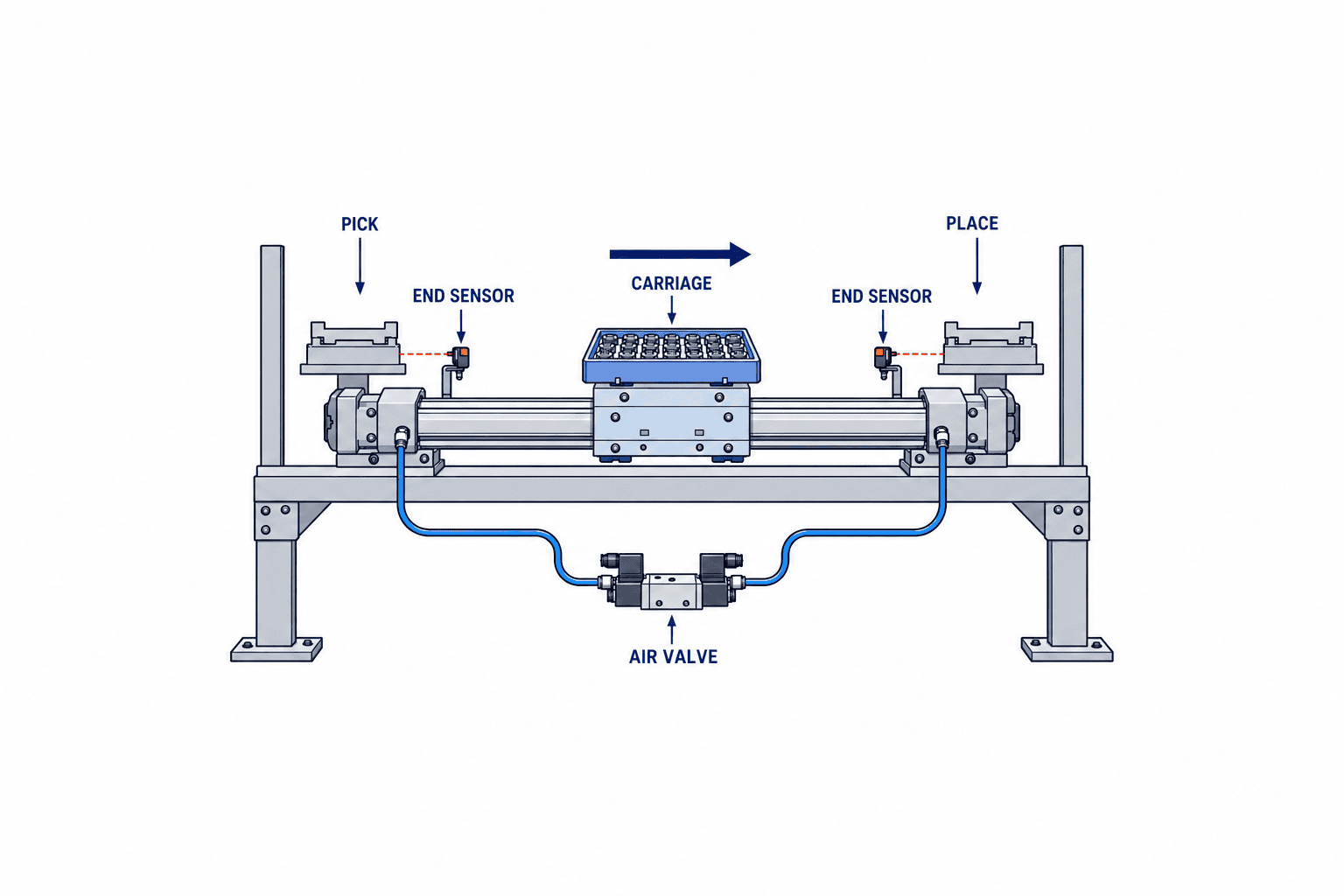
Fix the start and end of the real workpiece journey on one layout drawing. For example, a container transfer from an injection moulding machine to an inspection table needs more than the distance between machine centres. The effective stroke has to account for the carriage plate, end stops, fittings, hose bend radius and position needed for transfer. Overall installed length also differs from stroke because end caps, fittings and sensor mounts occupy space. Check the actual envelope against the guard and available maintenance access.
Next define whether the axis is horizontal, vertical or overhead; whether the return trip is loaded; whether it only needs two end positions or an intermediate stop; and what happens to the load if power or air is lost. A pneumatic two-position axis is not automatically a continuous precision positioning system or a safe holding mechanism for a heavy vertical load. If those duties matter, compare an electric actuator, mechanical restraint, brake, external guide or a different process arrangement as part of the same project.
Measure the operating installation, not just an open machine
Survey the machine with its guard in the operating position. A clearance measured only with the door open can disappear when the door stiffener or cable duct closes. Model the heaviest workpiece, the highest centre of gravity and the thickest changeover fixture separately along the full travel. For retrofits, record mounting-hole locations and the space required to remove a cylinder or slide. Where hoses move, check bend radius, wear points and places where a hose could catch.
Write the intended sequence: start permission, grip confirmation, forward movement, end detection, transfer confirmation and return. For each step, name the PLC input required to advance. A transfer confirmation or fault sensor discovered after the quotation changes the I/O count and panel work. The valve manifold and speed controller are part of the axis, too. Our guides to pneumatic solenoid valve manifold selection and pneumatic speed controller selection help define these interfaces.
Mechanical and magnetic coupling: choose by duty
In a mechanically coupled rodless cylinder, a connection through the cylinder slot transmits piston movement to the carriage, while a sealing band controls leakage. SMC’s MY1 and Parker’s OSP-P technical material illustrate this family. In a magnetically coupled design, magnetic force links an internal piston to an external slide without a through-slot; Festo describes it as a separate product category. Neither principle is always better. Compare required driving force, external forces, cleanliness, end stopping, access and service method.
Magnetic coupling can separate if an external force exceeds its specified capability. For a collision or abrupt stop, obtain the model-specific limit and test the recovery sequence at FAT. With a mechanically coupled product, inspect the sealing band, protective cover, contamination paths and replacement interval. In both designs, the application changes markedly depending on whether the load sits directly on the carriage or a separate guide carries its weight and moments.
The following is a starting comparison. Final approval still requires current model data and a test with representative loads.
| Issue | Mechanical coupling | Magnetic coupling |
|---|---|---|
| Transmission | Mechanical link between piston and external carriage | Magnetic link between piston and external slide |
| Overload review | Body, guide and mounting loads | Coupling limit and recovery after separation as well |
| Cleaning | Seal band and cover condition | Tube exterior and slide area |
| RFP question | Seal replacement, protection, guides, spares | Available force, separation condition, recoupling process |
“Rodless cylinder” may refer to an unguided basic unit, a plain-bearing guide or a precision linear guide. SMC’s MY1 data give permissible moments and load masses by configuration and require consideration of speed and end impact. Emerson’s AVENTICS RTC line also includes basic and higher-load variants. A request that merely says “one rodless cylinder” can therefore produce incomparable bids. State the guide type and the load case to be evaluated.
The centre of gravity matters before rated load mass
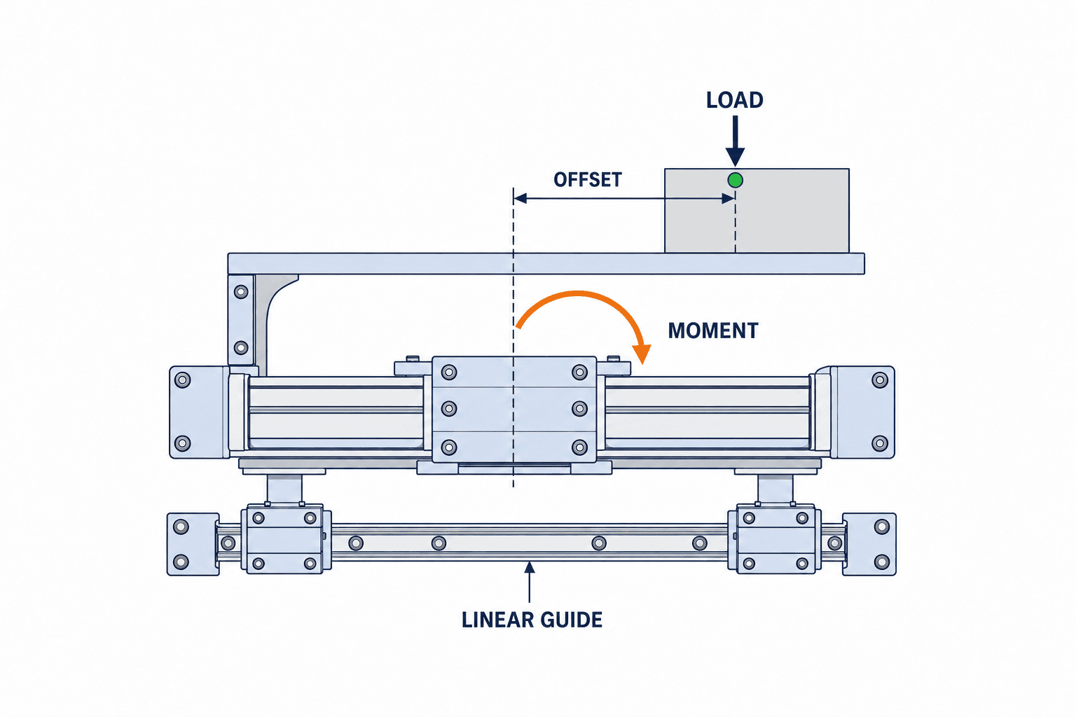
A workpiece can weigh less than a catalogue load limit yet exceed the guide’s permissible moment because its centre of gravity sits far from the carriage. Five kilograms on a long side bracket does not load the guide like five kilograms centred above it. Acceleration and deceleration add dynamic effects, particularly at the stroke end. In the RFP state the combined maximum mass of workpiece and fixture, three-axis centre-of-gravity coordinates, travel orientation, acceleration conditions and the expected position during an emergency stop.
SMC’s MY1 selection material expressly requires both allowable load and moment checks, including the dynamic moment from end impact. Do not take a static load value and apply it to a cantilevered fixture. If moments act in more than one direction, follow the manufacturer’s combined-load method as well as checking each direction. Request the supplier’s calculation sheet so an engineering change can be rechecked without reconstructing undocumented assumptions.
Watch units. Forces may be in newtons, moments in newton metres, mass in kilograms and offsets in millimetres or metres. Do not copy “5 kg” as “5 N,” use a 300 mm offset as 300 m, or equate theoretical cylinder thrust with available transfer force. Friction, pressure loss, valve flow, guide preload and orientation all affect the installed axis. Set margins using the current manufacturer’s sizing procedure and the factory’s design rules; a universal safety factor stated in a blog would be misleading.
Choose the mounting and guide arrangement
For a horizontal axis, check tipping and carriage roll. For overhead installation, check fastener retention and dropped-object risk. For vertical installation, examine what happens when air is lost. A long axis also needs its own support and deflection review. Even where a catalogue permits installation in any orientation, the bracket and support spacing must be verified against the model drawing. Parker’s catalogue shows dimensions for different cylinder-guide combinations. If support differs from published conditions, request written supplier confirmation and a physical test.
An integrated guide can reduce the number of components. Where a machine already has a stiff linear guide, it may be sensible to use the cylinder only for driving force. Two parallel guides, however, can bind if their alignment is wrong. Specify the reference face, parallelism, floating joint or compliance, thermal expansion allowance and assembly measurement method. “Adjust on site” is not a sufficient drawing note.
Specify stroke, speed and stopping together
Calculate effective stroke from transfer positions, workpiece and gripper protrusion, homing allowance and mechanical position tolerances. Extra stroke is not free: it increases overall length, air consumption and potentially cycle time. Check standard stroke increments, special-length lead time, future adjustment needs and spare-part availability. Record both effective travel and the machine’s maximum allowable installation envelope.
Catalogue maximum speed is not the cycle-time answer. Distance divided by target time gives an average; the actuator also accelerates, decelerates and waits for the grip, valve, end sensor, transfer and vibration to settle. The loaded forward stroke may differ from the unloaded return. Define the overall machine cycle and the exact timing points. AVENTICS publishes model-level speed, pressure and cushion data; a limit shown in such data is not an unconditional performance guarantee for a particular line.
Review built-in air cushioning alongside external shock absorbers and mechanical stops. Does the adjustment range cover the heaviest and lightest workpieces? What must happen on emergency stop or power loss? Will residual oscillation trigger a downstream sensor falsely? If position repeatability matters, measure mechanical datum repeatability separately from sensor triggering repeatability. Where many controlled positions are needed, reconsider the actuator and control method rather than assuming a two-position pneumatic cylinder will achieve them.
Include the real air supply in the equipment specification
Thrust and speed change if pressure falls at the actuator. Undersized branch piping, long hoses, restrictive fittings, an undersized valve or a blocked filter often appear only during site commissioning. State the working pressure range at the axis inlet, where it will be measured, which other air users operate simultaneously and the required air quality. Measure pressure while the axis moves; the compressor outlet gauge is not the same measurement.
For a high-cycle machine, estimate air consumption across operating hours, but do not equate a catalogue per-cycle volume multiplied by cycles with a guaranteed utility bill. Leakage, idle blowing, set pressure, compressor efficiency and pipe loss must be accounted for separately. Festo offers selection support and air-consumption calculation tools. Use the calculation as a start, then verify it with an on-site flow meter or operating record.
Safety is a system property, not a cylinder label
Even a small actuator can move a fixture into a pinch point or cause collision and falling-object hazards. ISO 4414:2010 covers general rules and safety requirements for pneumatic fluid power systems and components on machinery. Do not infer that a mark on an individual cylinder completes the machine’s risk assessment. Link the air circuit to the guard, stop system, residual-pressure release and restart prevention. The project owner must establish the applicable Thai requirements and customer standards for the specific installation.
For vertical and overhead axes, physically check load behaviour as pressure decays. If a load must remain in place, consider a mechanical fall-prevention device; do not treat friction in the air circuit as a safety-rated holding function. Document states for guard opening, emergency stop, power loss, air isolation and repressurisation. Avoid unexpected movement on return of pressure. Restart should require confirmation that people are clear of the hazardous zone.
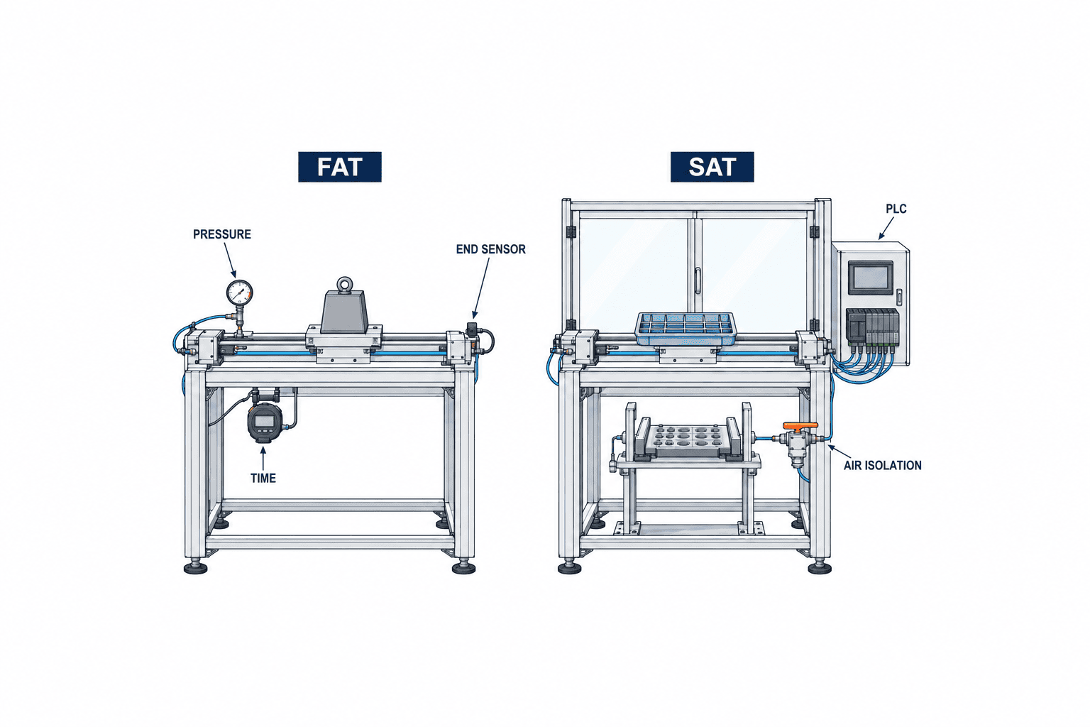
Residual air needs special attention during maintenance. Check valves and isolated volumes can retain pressure even after an upstream valve is closed. Match circuit drawings to isolation points and produce lockout and tagout instructions in the language technicians use. FAT should verify the intended circuit; SAT should test the installed main valve, exhaust path, indications and actual maintenance position.
Put comparable requirements and evidence in the RFP
“One rodless cylinder” is not enough for a comparable quote. Give each supplier the same load case and timing duty, then ask for a sizing calculation. Specify performance, environment and verification method before fixing a model number. If a value is unknown, state that it will be fixed by a named site measurement rather than leaving an apparently optional blank.
| RFP field | Buyer-supplied condition | Supplier evidence |
|---|---|---|
| Transfer load | Maximum mass, dimensions and centre of gravity of workpiece and fixture | Load drawing and permissible-moment calculation |
| Axis | Horizontal, vertical or overhead; effective travel | Envelope drawing and support spacing |
| Timing | Forward and return time, settling, timing points | Sequence and speed/cushion sizing |
| Air | Pressure at inlet, quality and simultaneous users | Force and valve/fitting/pipe flow calculation |
| Controls | PLC signals and grip/end/transfer checks | I/O list, circuit and fault-state table |
| Safety/service | Guard, pressure release and replacement space | Risk review, service procedure and spare list |
| Acceptance | Real workpieces, pressure, speed and pass criteria | FAT/SAT plan, measurements and corrective records |
Clarify scope: is the price only for the body, or does it include guide, brackets, sensors, speed controllers, solenoid valves, piping, PLC changes, guard, installation and commissioning? Mark each line as included, separate or buyer-supplied before comparing totals. Ask about local availability and lead times for seals, slides and sensors. If a Thai plant cannot afford an overnight stoppage, recovery time and the spare supply route matter as much as purchase price.
Avoid choosing a low bid with a missing guide
Break differences down by guide, cushioning, sensor count, tests and warranty. If one bid includes an integrated guide and another only an actuator body, the lower price still leaves guide engineering, installation and maintenance. Show capital cost, stoppage for installation, spare parts, compressed air and recurring checks on separate lines. State the assumptions behind projected labour savings, uptime and changeover frequency; a pre-installation estimate is not a measured return.
Score technical compliance as meets, conditional or fails. Price the extra test needed for each conditional item. Deferring actual-workpiece or safety tests to recover a short lead time can turn into a failed SAT. If model substitution is permitted, require evidence of equivalence for permissible moments, envelope, I/O and spare parts.
What to measure at FAT and SAT
FAT at the supplier checks the contracted configuration before shipment. SAT at the Thai plant repeats the essential checks using local power, compressed air, PLC, workpieces and operator routes. Neither test replaces the other. Use the same requirement identifiers in both test sheets so a buyer can trace a result back to the RFP.
At FAT, match the nameplate, stroke, ports, sensors and guide to approved drawings. Use a fixture representing maximum mass and centre-of-gravity offset. Record loaded and unloaded travel time, stopping behaviour, settling, detection and the state after an emergency stop. On a long axis, inspect midspan deflection, looseness at supports and hose snags. State the measured pressure and speed conditions instead of accepting “fast” or “quiet.” Keep instrument IDs, calibration status, tester and sample workpiece references with the result.
At SAT, include a pressure close to the plant’s lowest normal operating condition and a period with other air users active. Check whether pressure variation changes movement, cushioning or PLC timeout. Perform a real maintenance replacement once and record guard-removal time, post-replacement alignment, leak checking and restart. Confirm that Thai work instructions and field labels agree with the circuit drawing.
| Test | FAT evidence | SAT evidence |
|---|---|---|
| Stroke and clearance | Dimensions, travel ends, dummy workpiece | No interference throughout the real machine travel |
| Load and stop | Video, timing and position with maximum load and offset | Repeated results with actual workpiece and site air pressure |
| Fault state | Power loss, emergency stop and air isolation | Installed main valve, guard and PLC response |
| Maintenance | Removal procedure and required tools | Access, locally stocked parts and recovery time |
Agree the sample count and pass/fail limits in the contract. Ten successful empty strokes do not establish performance with normal variation, yet an arbitrary enormous no-load endurance test is also weak evidence. Build a matrix from required cycle rate, product variants, supply pressure and load. Include the heaviest load, lowest planned pressure and hardest stopping condition. Define how a failed test is corrected and repeated, including deadlines and responsibility.
Installation and maintenance in a Thai plant
Specifications and the technicians who maintain the machine may use different languages. Handing over only Japanese design notes can mean waiting for a vendor every time a cushion is tuned or a sensor replaced. Document model, settings, exchange order, safe state after a fault and the restart check in the operating team’s language. Keep initial values and change history so a post-maintenance check has a baseline.
In hot, dusty or chemically washed areas, do not assume generic catalogue ambient conditions apply. Match the manufacturer’s temperature, seal, cover and corrosion limits to measured site conditions and cleaning procedures. Check that an added cover does not block servicing and that dust will not obstruct a sensor slot. For cleanroom or hazardous-area use, verify a purpose-specific product and certification with the manufacturer rather than extending a standard model by analogy.
“Stock one whole cylinder” is not the only spare strategy. Ask which seal, sensor, fitting, hose or guide components can be replaced in the field. Some units require supplier adjustment after disassembly, making a complete spare unit the faster recovery option. Separate locally available components from imported ones and size inventory against lead time and tolerable downtime. Clarify which parts, cycles and maintenance practices the warranty covers.
Build a realistic implementation sequence
Separate site survey, specification freeze, quotation, design approval, material order, FAT, shipment, installation, SAT and production ramp-up. For a retrofit, reserve the available line-stop window first and complete as much piping and wiring as possible at FAT. An unbuffered plan fails when a sample workpiece is late or an as-built drawing differs. Include sample delivery dates, approvers, stoppage window and the due date for local-language procedures in the schedule.
Run a small real-workpiece trial before freezing the model
When drawings and catalogue ratings do not settle the choice, run a short trial with actual production parts. Do not test only the heaviest part. Include a thin part that may oscillate, a part with an offset centre of gravity and one with a compliant grip surface. Choose the most demanding orientation for adjustable fixtures. Record mass, centre of gravity, gripping method and mounting so results can be compared quantitatively as well as on video.
A vendor’s test rig and the production line may have different air supplies and hose lengths. Separate vendor-standard, normal Thai-plant and expected low-pressure conditions. Identify which pressure was measured at the actuator inlet; do not confuse it with a compressor gauge. Measure not only travel time but also the time from arrival until the load is stable enough for the next process to receive it safely.
Observe carriage binding, noise near the seal, guide play, bracket flex, workpiece slipping and sensor chatter. If any occur, lowering speed alone does not establish the root cause. Check guide capacity, centre-of-gravity offset, cushioning, air flow and support stiffness. Recheck fastener condition and leakage after the run. A trial with real parts finds installation problems that a catalogue sizing chart cannot reveal.
If the trial changes the model or bracket, record a drawing revision. State in the RFP that the production configuration must match the tested one and that substitutions require an equivalence calculation and, where needed, a repeated test. Success with temporary piping, provisional sensor positions or a high test-lab supply pressure is not proof of production-line performance.
Provide traceable samples and request traceable results
Identify each sample with part number, mass, centre of gravity, surface condition and allowable marking. For multiple variants, select representative limits for weight, shape and grip position and document why. Request the supplier’s sizing sheet, test conditions, results, video, recommended model and residual risks under the same revision number. A bare pass/fail statement will not tell the plant whether a new product variant fits six months later.
A workpiece trial does not replace safety engineering. Return access and stop behaviour to the machine risk assessment and repeat the relevant checks at FAT and SAT. In a test room, hoses may be exposed and easy to see; within a production guard, the same hoses can be inaccessible during service. Acceptance should check safe inspection and replacement as well as successful travel.
Preserve failed attempts, too. A run that missed the end position at low pressure, tilted a workpiece or required long manual recovery is useful evidence. Keep every test condition and result, not only a successful average; repeat the same challenge after a correction. Record the approved workpiece and speed envelope in the operating procedure and require reassessment for variants outside it. Keep initial stopping time and air pressure as a maintenance baseline. Share the baseline with production engineering and quality as well as maintenance. If travel time drifts, investigate leakage, filtration, valves and guide resistance before simply raising pressure. Record the reason and owner for any setting change so later defect investigations can reconstruct machine conditions.
Frequently asked questions
How should rodless cylinder costs be compared?
Compare the same scope: actuator, guide, sensors, valve, speed control, piping, PLC work, guarding, installation, tests and spares. Compare mechanical and magnetic coupling only against the same duty. Public prices vary by configuration, country and time; obtain formal Thai-market quotes against one RFP rather than treating a web price as a project budget.
Can a rodless cylinder handle any long stroke?
No. Festo and AVENTICS describe long-stroke families, but each model has limits for load, support, speed, pressure and environment. Provide effective travel, overall envelope, centre of gravity and stop duty. A family maximum is conditional, not an installed-machine guarantee.
If load mass is within the rating, can we skip guide calculations?
No. An offset load, acceleration and end impact can exceed permissible moments even when mass is within a simple limit. SMC’s sizing guidance requires both mass and moment checks. Obtain the supplier’s calculation and use a representative severe load case at FAT.
Should safe stopping be checked at FAT or SAT?
At both. FAT checks the planned circuit and basic response to air isolation and emergency stop. SAT tests the installed PLC, guard, main valve and real work area. Vertical and overhead axes need particular attention to dropped-load prevention and unexpected movement when air returns.
What should a retrofit survey measure first?
Measure travel, clearance with guards shut, maximum workpiece and fixture mass and centre of gravity, dynamic pressure near the axis, available PLC I/O, line-stop window and space for replacement. Choosing a model before these are known often causes late piping, guarding and sensor additions.
Conclusion: select for the real loaded stop
A rodless cylinder can deliver long linear travel in a compact installation. The purchasing decision, however, is whether the real load and fixture can move within the required time, stop safely and be restored by the local team. Compare coupling principle, guide moments, air supply, stopping and service in one specification, and bind the requirements to FAT and SAT evidence.
If you are considering a long-stroke transfer or a retrofit at a Thai factory, contact TOMAS TECH while the workpiece, layout and cycle assumptions are still being defined. We can help turn site conditions into a practical RFP and acceptance plan.


