


Selecting a control panel cable gland is easy to reduce to a thread size: “Use M20 everywhere.” That shortcut can leave a gap around the cable jacket, an unsealed panel face, excessive load on a terminal, or a broken shield connection. Humidity, washdown, rain, dust and vibration also vary between Thai production lines. This guide connects the cable schedule, enclosure opening, required protection, RFP, FAT and SAT into one specification that a supplier can build and an owner can verify.
In brief: Check the gland’s entry thread and its cable clamping range separately. Then verify the panel-side gasket, cable jacket, strain relief and, where needed, EMC shield termination. A product’s IP marking alone does not establish the ingress protection of a modified, assembled control panel.
1. Define the boundary of control panel cable gland selection
A gland does more than pass a cable through sheet metal. It seals the penetration, holds the outer jacket so that pull is not transferred directly to the terminals, and in some designs connects the screen to a conductive enclosure. IEC 62444:2010 addresses construction and performance requirements and tests for complete cable glands for electrical installations. Citing the standard is useful, but it does not select a product or confirm its installed condition.
The subject belongs within overall control panel design and FAT. This article concentrates on the panel penetration. Conductor termination is treated separately in our terminal block selection guide, and enclosure heat management in the cooling fan guide. A gland cannot compensate for a poor terminal connection or solve a heat problem.
Select by individual entry, not by panel. Motor power, encoder, sensor and Ethernet cables differ in outer diameter, movement, screening and replacement needs. Build a cable schedule with cable part number, nominal and measured outer diameter, tolerance or approved substitutes, jacket material, screening, entry location and maintenance frequency. Measure a real cable where practical: a conductor cross-section or a nominal catalogue size is not an adequate substitute for jacket diameter.
What counts as acceptance?
Acceptance means that the stated cable and gland fit within the product’s published limits, that both sealing interfaces are assembled to the manufacturer’s instructions, that the cable is supported as designed, and that required ingress and EMC conditions can be checked. State which assembled condition will be inspected and by which test or observation. “The cable fits through the hole” is not an acceptance criterion.
2. How to interpret a cable gland IP rating
IEC 60529 classifies the degrees of protection provided by electrical enclosures using the IP code. The first characteristic numeral concerns access to hazardous parts and ingress of solids; the second concerns water ingress. A gland’s advertised rating applies to the product under its stated test conditions. Manufacturers may state particular pressure, depth or duration. Do not assume that the same “IP68” marking establishes suitability for every washdown, outdoor or immersion scenario.
The finished panel adds other leak paths: hole diameter, damaged threads, coating and flatness, gasket or sealing washer, cable jacket damage, unused openings and door seals. Rittal’s gland-plate data illustrates that protection is conditional on correct installation. Write the product rating and the required rating of the finished assembly as separate requirements.
Describe the environment before choosing a number: indoor dust and wiping, occasional splash, hose cleaning, rain exposure, condensation, oil and chemicals. Record the direction, pressure and frequency of cleaning and whether temperature changes make condensation likely. A humid Thai factory does not automatically call for an IP68 gland; the whole enclosure needs an appropriate protection and thermal strategy.
Three checks before accepting the IP claim
First, verify the exact part number, clamping range, accessories and test conditions in the manufacturer’s data. Second, verify that panel thickness, entry hole, thread engagement and gasket match the installation instructions. Third, define the finished-assembly inspection or test in the project specification. Visual inspection and a client-defined water test serve different purposes; do not label a panel “IP68 equivalent” without a defined method.
3. Cable diameter selection: measure the outside jacket
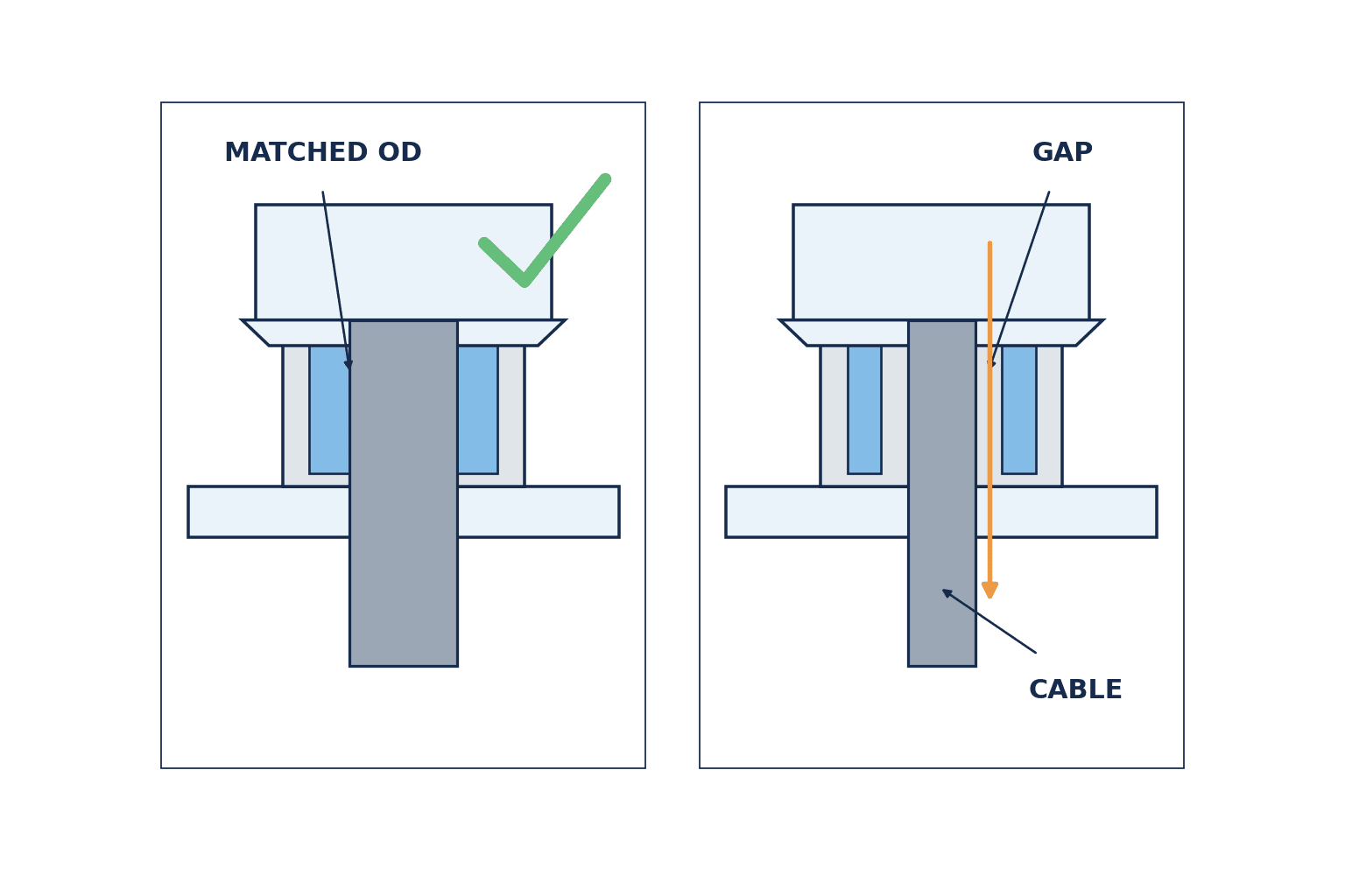
Conductor area and core count do not determine the gland size. A four-core 2.5 mm² cable may have different outer diameters depending on insulation, shield, jacket and manufacturer. The sealing insert normally bears on the outer jacket, so record that diameter. LAPP’s sizing guide explains measurement and matching to the stated clamping range. Phoenix Contact’s catalogue shows that the same entry thread can be offered with different clamping ranges.
M20 × 1.5 describes the panel-entry thread; it does not uniquely describe a sealable cable diameter. For one specified LAPP SKINTOP ST-M range, the guide lists an M20 × 1.5 product for cable outer diameters from 6 to 13 mm. This is a product example, not a universal rule for all M20 glands. Put the exact gland part number, its clamping range and the actual cable diameter in the approved schedule.
A nominal diameter on the edge of the permitted range can move outside it when a cable supplier or production lot changes. Check tolerances and replacements. Avoid treating “the middle of the range” as a guarantee: flat cables, multi-entry seals and special inserts have their own compatibility rules. Grip and sealing must both be checked without damaging the jacket.
| Cable-schedule field | Example | Purpose |
|---|---|---|
| Entry ID and destination | C-01 / motor M1 | Connect drawings, photos and tests |
| Cable part and jacket | Exact part / oil-resistant PVC | Control substitution and compatibility |
| Outer diameter | Nominal plus measured value | Compare with clamping range |
| Screen | Braided / none | Determine EMC entry needs |
| Panel entry | Thread, opening, sheet thickness | Check mechanical fit |
| Environment | Water, oil, UV, vibration | Choose materials and protection |
| Gland assembly | Part, washer, nut, blank | Buy and maintain the same assembly |
Do not push several round sensor cables through a standard seal intended for one cable. Use a purpose-designed multi-cable entry and matching inserts. Record each cable diameter and how unused holes are blanked. A future spare opening should be sealed with the manufacturer-approved plug until used.
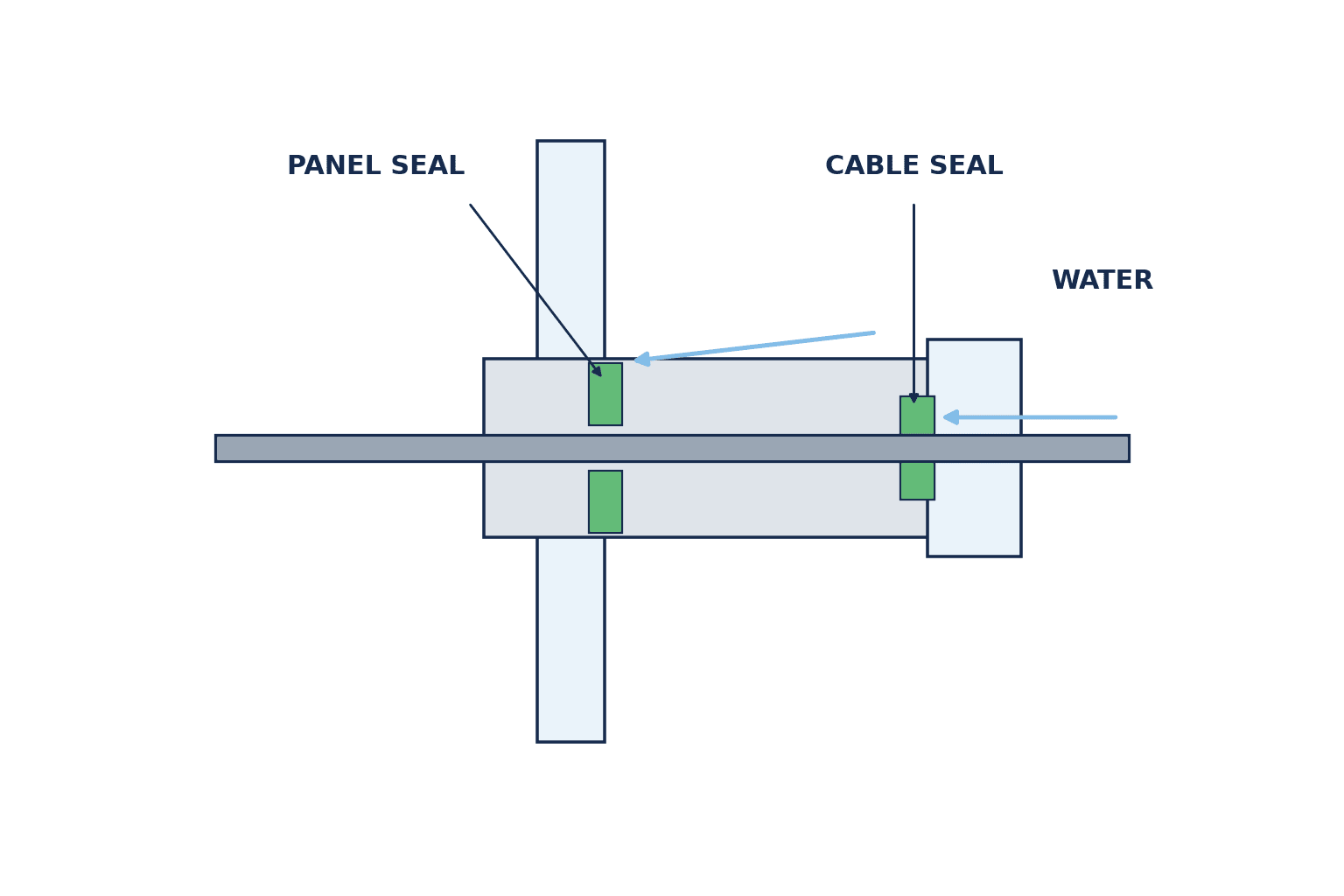
4. Water protection has two sealing interfaces
There are two important interfaces: gland to panel, and seal to cable jacket. A perfect cable seal cannot fix a damaged panel-side gasket; a perfect panel joint cannot fix an undersized jacket. Trace the possible water path in section view, including water running down the cable toward the entry.
At the panel face, inspect hole diameter, burrs, coating, surface flatness, sheet thickness and effective thread length. Include the specified washer, O-ring or locknut in the bill of materials. Do not force a metric gland into an existing PG thread: the thread forms are not interchangeable. If an adapter is used, check every added sealing interface and the manufacturer’s stated protection conditions.
At the cable, inspect the jacket for cuts, flattening and chemical deterioration. More torque is not automatically better: excessive tightening can deform the insert or jacket. Use the model-specific installation instructions for tools and torque; a single generic torque value across products is unsafe. Provide a suitable external support point so that the terminal is not the mechanical anchor. A fixed gland also cannot by itself qualify a repeatedly moving cable: assess the cable’s flex rating, bend radius and support separately.
Entry location also matters. Where possible, avoid an upward-facing panel surface on which rainwater collects, and route the cable so that rain or wash water does not run toward the entry. Maintain the specified bend radius. Assess the gland’s strain-relief ability separately from an external cable clamp or support point so terminals do not serve as anchors. For a cable subject to vibration or repeated motion, evaluate its flex rating and fixing points as well as the fixed gland.
Choose material from the actual environment
Polyamide, nickel-plated brass and stainless steel each suit different conditions. Compare oil and cleaners, UV, temperature, corrosion, mechanical load, EMC and local spare-part availability. Food or chemical washdown may impose additional surface and material needs. Confirm chemical compatibility with the manufacturer; test or seek product-specific advice when the fluid is not covered by the data.
5. An EMC gland needs a complete shield path
Motor-drive and sensitive signal cables can lose shielding continuity at the cabinet entry. An EMC gland provides a contact mechanism between the cable screen and a conductive enclosure. Rittal’s EMC gland data identifies cable and minimum shield diameters and explains its conductive locknut arrangement. Those statements describe that product, not an unconditional result for every painted or plastic panel.
Specify where braid is exposed, how the gland contacts it, and how the gland reaches the enclosure’s conductive reference. If coating or a plastic wall interrupts that path, follow the manufacturer’s prescribed connection method. Some products specify distinct permitted diameters for cable jacket and screen; verify both. Follow the drive and cable manufacturer’s EMC instructions for the termination geometry. Do not confuse a functional screen connection with the protective-earth conductor.
6. Compare offers by missing requirements before price
If one supplier quotes a bare gland, another includes a gasket and locknut, and a third includes EMC parts and installation, their unit prices are not comparable. Request the exact product data, installation instructions, accessories, environmental limits, certificates where applicable, local lead time and spare parts. Separate design entries, spare openings and maintenance stock.
| Criterion | Product-document check | Site check |
|---|---|---|
| Thread and opening | M/PG/NPT, size, sheet limit | Measured opening and seating face |
| Diameter | Published clamping range | Measured cable jacket |
| Ingress | IP marking and test conditions | Assembly requirement and acceptance method |
| Materials | Body and seal composition | Oil, cleaning fluid, sun and temperature |
| Relief | Product retention claims | Supports, vibration, terminal load |
| EMC | Contact design and shield range | Ground path and braid preparation |
| Maintenance | Disassembly and spare parts | Local stock and tools |
“IP68, M20, stainless” is not an adequate technical approval. Confirm that every submitted value belongs to the offered part number rather than to a family-level catalogue example. For Thai sourcing, define which substitutions are allowed and who approves them. An apparently similar local item can have a different seal material, diameter range or EMC function.
Continuity of supply in Thailand matters. A gland imported for the original build may be unavailable during a later machine shutdown, especially if its matching seal or locknut is not stocked locally. The purchasing schedule should record the manufacturer part number, permitted-equivalent criteria, substitution approver, separate seal and locknut part numbers, and lead time. Do not leave “equivalent allowed” unexplained: compare cable OD range, thread, IP test conditions, material, EMC function and installation instructions before approving a substitute.
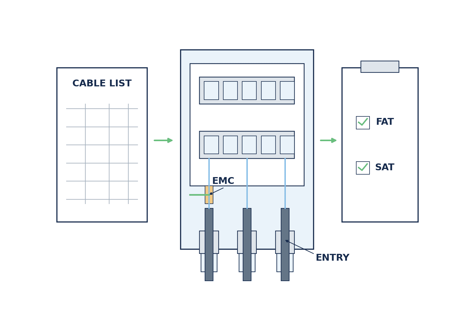
7. Put cable glands in one RFP–FAT–SAT traceability table
An RFP should join each entry ID to the cable, hole, gland and acceptance method. Use the same ID on the drawing, cable schedule, BOM, assembly photograph and test record. See the wider control-panel procurement guide for responsibility boundaries.
An example row is: “C-01; approved cable part and measured OD range; M20 × 1.5 panel entry; exact gland and accessory part numbers; required IP condition; installation instruction revision; FAT dimensional and visual checks; SAT check after actual field cable installation.” This is a format example, not a recommendation that every project use M20 or any particular IP rating.
FAT: evidence before shipment
Compare approved drawings, entry positions, opening dimensions, product labels, cable schedule and BOM with the built panel. Check burrs, damage, gasket and nut presence, unused-entry closure, jacket fit and the recorded assembly method. For EMC entries, document the shield contact and conductive path. Approve the scope and pass criteria of any test before performing it. If the actual field cable is unavailable at FAT, label final cable-fit verification as a SAT item rather than treating a temporary cable as final evidence.
SAT: evidence after field installation
Repeat the critical checks with the actual cable and routing: diameter, jacket condition, bend, supports, water path, maintenance access and unexpected pull on terminals. A new hole drilled at site is a design change: approve machining, gland, inspection and as-built drawing together. Keep spare entries sealed.
| Item | FAT record | SAT record |
|---|---|---|
| Position and product | Approved drawing, BOM, photographs | As-built drawing and photographs |
| Cable fit | Part and range cross-check | Actual cable measurement and assembly |
| Panel face | Hole, gasket, locknut check | Recheck any field modification |
| Relief and EMC | Planned support and connection | Actual routing and conductive path |
| Unused holes | Blank-off record | Final closure after additions |
8. Four common failure situations
Diameter inferred from conductor size. A cable may pass through but fail to compress the seal. Measure the actual jacket at an undamaged point and select a specified range; buying an oversized gland is not a safe default.
Opening and thread confused. An old PG entry is not made compatible with a metric gland by force. Check thread type, pitch, hole and sheet thickness on the actual panel; use an approved adapter if suitable.
Only the gland has a high IP marking. An open knockout, damaged door seal or poor routing can still admit water. Find the leak path across the finished enclosure before replacing all glands.
Unapproved local substitution. Two M20 items may differ in clamping range, seal or shield capability. Require design approval, revised drawing and updated inspection items before installation.
9. A practical decision sequence
Start with the panel environment and cable list. Agree the required protection and acceptance method for the assembled panel. Freeze cable part numbers and diameters, then the location and thread of each opening. Compare exact product data and installation instructions, including washers, nuts and blanks. Review EMC with electrical engineering, hole machining with mechanical engineering, service access with production engineering and continuity of supply with purchasing. Finally, keep the RFP, drawings, BOM and FAT/SAT records at the same revision and update the as-built set after field changes.
Ask whether a different technician could select, install and check the same part six months later. If the diameter, panel interface, seal components, installation instruction or acceptance criterion is missing, resolve it before purchase. Small component cost does not mean small rework cost once dozens of entries are installed.
Pre-purchase review example: an illustrative case to adapt
Imagine a washdown packaging line with one motor cable and four sensor cables entering a control panel. Ordering five “IP68 M20” glands immediately would overlook the difference between the motor cable and the much smaller sensor cables. List each exact cable part and outer-diameter range, then measure representative physical cables. Compare five individual glands with a purpose-designed multi-cable entry for the four sensors, considering available panel space and maintenance. If using the multi-cable option, check the selected product’s instructions both with unused insert holes and with all four cables fitted. The cable counts and arrangements here are hypothetical, not a recommended configuration for a specific machine.
Ask site staff exactly how cleaning is done. “Water is used” does not distinguish wiping from a directed hose. If a cleaner is applied, record its name, concentration and temperature, whether power is isolated during cleaning, and the direction of exposure. Where published data do not establish compatibility of the gland body and seal with that chemical, ask the candidate manufacturer. Set the required protection of the complete enclosure and the site test method from customer, equipment and applicable project requirements; do not derive them backwards from a component catalogue claim.
If the motor cable is screened, transfer the drive manufacturer’s wiring instructions into the drawing. Review where the screen is exposed, whether the gland contact touches the braid, and how a conductive path is created through a painted panel. Some sensor cables are unscreened, so every entry need not use an EMC gland. Conversely, buying an EMC gland does not eliminate the need to prepare the shield termination. Classify each cable-schedule row as standard or EMC and support that choice with the part number and assembly drawing.
At FAT, photograph burr removal and gasket placement while these details remain visible during panel manufacture. At SAT, inspect actual routing, spare length, supports and cable OD. If the cable part number changes on site, compare its OD again with the installed gland’s clamping range and reselect the gland if the range is exceeded. Record the substitute cable part, OD, affected entry ID and approver in a field change notice so later replacements do not repeat the error.
Ambiguous wording to remove from a specification
“Use waterproof glands” does not define water exposure or acceptance. “Approximately M20” confuses entry thread with cable diameter. “Local equivalent allowed” gives no equivalence criteria. “Installer to decide” leaves conformity ownership unclear. Replace those phrases with an entry ID, exact gland and accessory parts, accepted cable OD range, panel machining conditions, product test conditions, installation instructions, substitute approval and inspection record. The RFP need not be long: consistent columns in the cable schedule and notes for exceptions are easier to compare than vague prose.
The same discipline applies to replacements. A store-bin label reading only “M20 cable gland” can mix standard and EMC versions or products with different clamping ranges. List the manufacturer part, gasket, locknut and blanking plug separately in the maintenance BOM. When a source changes, approve the replacement against the original functions and permitted ranges, not by appearance. Selection is complete only when design information reaches the maintenance team.
When drawings and the installed panel disagree
In retrofit work, the recorded opening location or thread may differ from the physical panel. Buying against the drawing alone encourages field improvisation such as enlarging holes or moving spare glands to other openings. Before work, give every entry a numbered photograph and measured dimensions. Mark surfaces that cannot be measured as “unverified” and add a pre-start check. If an existing cable cannot be removed, identify its jacket and part number and plan a measurement during a shutdown.
Adding or enlarging an opening affects enclosure protection as well as strength and wiring space. Put machining approval, burr removal, coating repair, sealing surface, part installation, inspection and drawing revision on one change record. Check that coating repair and the EMC conductive connection can coexist. After fitting the part, reassess the whole panel, including unused openings. Give maintenance the latest as-built drawing and parts list matched to local spares.
When an entry fails acceptance, classify the cause instead of simply tightening again. An out-of-range OD needs a different product; a missing gasket needs the part and assembly procedure corrected. A deformed sheet or oversized hole needs a repair designed for that interface. Poor shield contact requires inspection of coating and screen preparation. Correct the cause and record retesting under the same entry ID so FAT and SAT evidence remains useful during maintenance.
10. FAQ: cable gland selection
Is the gland’s IP rating the panel’s IP rating?
No. Product testing and finished-enclosure performance involve different assemblies. The panel includes holes, gaskets, doors, unused openings and cables. Define the acceptance condition and verify the installed assembly; do not confuse IEC 60529 classification with a manufacturer’s particular test claim.
Which cable diameter should I measure?
Measure the outer jacket where the gland seal will grip. Record nominal and measured diameter and tolerance, then compare with the exact product’s clamping range. Core count and conductor area alone are insufficient. Flat or multiple-cable entries require purpose-built seals.
Does an M20 gland fit every M20 opening?
Confirm thread form and pitch, hole, panel thickness and sealing face. M20 does not specify cable diameter. Existing panels may have PG threads or damaged openings; inspect the actual part before ordering.
What should be checked first when water enters at a cable entry?
Trace the path: panel-to-gland joint, gland-to-jacket seal, unused openings, door seal and routing. Identify the cause before changing all parts. Follow electrical isolation and site safety procedures during inspection and testing.
What is the minimum cable-gland content for RFP, FAT and SAT?
Use the entry ID, exact cable and OD, panel opening, gland and accessories, IP/EMC requirements, installation instructions, inspection method and pass criteria, and change approval. If the final cable is unavailable at FAT, reserve its fit check for SAT.
Conclusion
Select the gland by cable and entry, not by thread alone. Confirm jacket diameter against clamping range, panel-side seal, environmental IP condition, strain relief and any EMC path. Carry one entry ID through RFP, drawings, FAT and SAT so that the installed result can be checked and maintained.
For a new or modified Thai factory control panel, TOMAS TECH can help organize the cable schedule and entry conditions even while panel drawings are still being developed. Site photographs and the water, dust, vibration and EMC requirements are useful starting inputs. Contact TOMAS TECH.
Primary references
- IEC 62444:2010 — construction and performance of cable glands.
- IEC 60529 — enclosure IP classification.
- LAPP cable-gland sizing guide (2026) — measured OD and product clamping ranges.
- Phoenix Contact control cabinet accessory catalogue — thread and range examples.
- Rittal EMC gland SZ 2843250 — shield contact and dimensions.
- Rittal KX gland plate SZ 1581200 — installed-condition qualification.
Verify the latest product data, installation torque, chemical compatibility and project-specific requirements for the selected items before purchase or testing.


