


Selecting a pneumatic speed controller by fitting size alone can leave a machine that extends too fast, changes speed when a workpiece is added, or jumps on restart. First define the movement in each direction, which air path will be throttled, and how performance will be measured with the actual load and piping. This guide covers circuit choice, flow data, installation, an RFP, and FAT/SAT evidence for a factory in Thailand. A speed controller adjusts normal motion; safety functions require a separate risk assessment.
Specify the movement before choosing an adjustment knob
A one-way flow control valve combines a throttle and a check valve. It restricts air in one direction and provides a freer path in the reverse direction. Festo distinguishes exhaust-air and supply-air versions. Both can adjust advance and return speed when applied to a suitable pneumatic drive. Thread and tube sizes alone do not identify the throttled direction, flow characteristic, or usable adjustment range.
Record cylinder bore, rod diameter, stroke, orientation, tooling and workpiece mass, guide friction, target cycle, required extension and retraction times, normal and reduced supply pressure, and the models of the directional valve, tube, fittings and silencer. State whether each direction requires its own speed. SMC’s technical material explains that actual speed depends on the combined effective areas of tubing, fittings, directional valves and silencers as well as the controller. An undersized component elsewhere in the circuit can dominate the result.
| Specification item | What the buyer should provide | Acceptance evidence |
|---|---|---|
| Motion | Extend/retract, horizontal/vertical, load cases and contact point | Video and machine log |
| Timing | Separate limits for each direction and any endpoint dwell | Repeated measurements under the same conditions |
| Air circuit | Cylinder, valve, fittings, tube, silencer and pressure range | Circuit drawing, bill of materials and pressure record |
| Adjustment | Meter-out/in choice, location and locking method | Installed flow direction and setting record |
| Abnormal conditions | Air loss, pressure drop, emergency stop and restart | Risk assessment and test record |
Meter-out versus meter-in: choose for this actuator and load
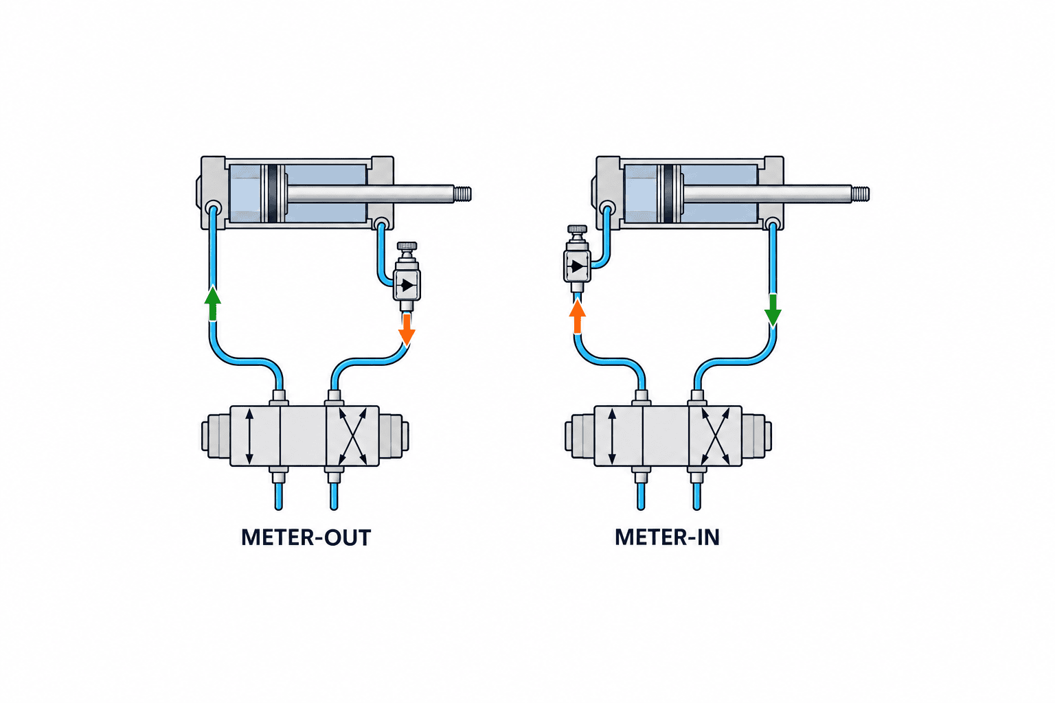
Meter-out restricts air leaving the cylinder, while incoming air flows more freely through the check path. Festo describes a piston moving between air cushions with free supply and throttled exhaust, which can improve motion as loads change. An SMC manual for a particular cylinder family also describes meter-out as the usual arrangement. These statements make it a useful first candidate, not a rule that guarantees stability for every machine.
Meter-in restricts incoming air and leaves the exhaust path freer. It can be considered where an actuator manufacturer’s circuit example or a specific application calls for it, including certain single-acting or low-speed arrangements. Air compressibility and an assisting external force can make motion unstable. The SMC CA2 manual cautions that its cylinder can operate unstably with supply-side throttling. This is a reason to test the proposed arrangement under the actual load, rather than claim that every meter-in circuit is unsafe or ineffective.
Extension and retraction are separate movements. During extension, the rod-side chamber exhausts; a meter-out controller on that exhaust path governs the extension. During retraction, the cap-side chamber exhausts. Identify ports and flow direction on the circuit drawing, and label the corresponding movement at the machine. A note that merely says “right-hand knob = extend” becomes unreliable after a cylinder is reversed or piping changes.
Vertical loads and safety stop need their own design
Gravity assists motion in one direction on a vertical axis. Air loss, a disconnected tube and residual pressure have to be considered. A speed controller is a normal-running adjustment component. It is not by itself proof of load holding, fall prevention or an acceptable emergency-stop distance. Whether a rod lock, mechanical catch, stop, receiving tray or another measure is necessary follows from the risk assessment and the approved equipment design. ISO 4414:2010 sets general rules and safety requirements for pneumatic systems and components; citing the standard does not certify a particular circuit.
Restart is also a distinct state. One chamber may retain pressure when supply is restored, allowing unexpected motion. SMC publishes a dedicated extension-prevention product example, but it still requires application-specific checking. In FAT and SAT, test loss and restoration of air, reduced pressure and a loaded restart through procedures permitted by the risk assessment. Do not use normal cycle-time results as a substitute.
Select flow by the complete circuit, not nominal size alone
A valve with high maximum flow is not automatically the easiest one to adjust. It may offer too little resolution in the needed low-speed region. Conversely, a valve may be fully open and still fail to reach the target speed. Start with stroke-time and maximum-load requirements, narrow candidates with the manufacturer’s sizing material, then test or model the valve, tube, fittings and silencer together.
Catalog flow data have test conditions. One Festo document defines a standard nominal flow condition with 6 bar inlet, 5 bar outlet and 20°C. That number cannot simply be treated as the same as another vendor’s value or as cylinder speed on the production machine. SMC separately plots needle opening against flow and against cylinder speed. A comparison should state units, inlet and downstream pressures, whether the figure is controlled or free flow, and the measurement method.
Worked example: define what must be measured
For an illustrative requirement of a 100 mm stroke, 0.50 s extension and 0.80 s retraction, the endpoint-to-endpoint average speeds are 100 mm / 0.50 s = 200 mm/s and 100 mm / 0.80 s = 125 mm/s. These are averages. They are not peak speeds, impact speeds, or air consumption. Cylinder and rod dimensions, pressure, compressibility and restrictions elsewhere in the circuit are still needed to estimate flow. It would be misleading to turn 200 mm/s into a universal controller L/min rating.
Measure the two directions separately with no workpiece, a normal workpiece and the maximum specified workpiece. The buyer must define timing tolerance, allowable workpiece movement, endpoint impact and interference with other axes. A 0.50 s stroke does not establish either machine safety or actual line throughput.
Adjustment resolution matters as much as maximum flow
SMC describes an equal-percentage flow characteristic that can make fine adjustment easier in a low-flow region. The same technical document notes that a linear characteristic can be preferable under certain low-speed conditions. Neither profile is universally best. Compare repeatability in the actual operating region and document knob turns or indicator position. Indicator-equipped and lockable models may make replacement and setup more consistent, but an indicator is a setting reference, not an independent measurement of motion. Confirm actual stroke timing after locking.
Observe more than average speed
Evaluate mid-stroke motion and endpoint deceleration separately
An actuator can meet the total stroke time while pausing partway and then moving too fast near the end. It can also travel quickly at first but spend too long near the endpoint. Divide observation into start, a defined intermediate position and the endpoint. If using video, fix the camera angle and scale. If using sensor timestamps, state exactly which physical event each sensor detects. Different reviewers should be able to interpret the same measurement in the same way.
Do not assign all endpoint impact control to one speed controller. A cylinder cushion, external shock absorber, mechanical stop and workpiece contact surface have different functions. Slowing the entire stroke may reduce impact but may compromise cycle time or the opposite direction. Read the cylinder manufacturer’s allowed kinetic energy and cushioning instructions, then inspect the real workpiece and mounting at the endpoint. A quieter stroke does not rule out side loading of a fixture or guide binding.
Raising air pressure to compensate for slow movement affects component ratings, thrust, endpoint impact and energy use. If pressure and throttling are changed together, the cause of any improvement becomes unclear. Limit the variables changed in one comparison and keep a setting history that allows a return to baseline.
Distinguish single-acting, double-acting and two-speed requirements
A double-acting cylinder often permits separate settings for extension and retraction; a single-acting one behaves differently because a spring or external force participates. Festo publishes distinct examples for single- and double-acting circuits. Do not mechanically copy a two-valve, double-acting layout into a single-acting circuit. Before assuming the return can run faster because it carries no workpiece, assess interference during return, worker access and downstream timing.
If motion must be fast in transit and slow immediately before contact, one knob that throttles the entire stroke does not fully specify the requirement. Position sensing, switching valves or a dedicated two-speed circuit may need to be included. SMC shows a dual speed-controller product that adjusts inlet and exhaust simultaneously, but that product description does not prove suitability for every two-speed profile. Define the required speed profile, switching position and power- or pressure-loss state first.
At very low speed, friction and load variation can interrupt smooth travel. Observe stopping, restarting and small fluctuations at the opening actually used, not just maximum catalog flow. Consider checks after warm-up rather than accepting a single trial immediately after commissioning. If the required repeatability is difficult to achieve with the selected pneumatic arrangement, review the guide, load and drive method as well.
Separate leakage and contamination from a setting problem
Gradually changing speed does not necessarily mean the knob moved. Small fitting leaks, damaged tubing, clogged filters or silencers, altered solenoid response and changing slide friction are other candidates. Record supply and running pressure, setting and load, and compare them with a known-good state. Follow manufacturer instructions and the machine’s safe procedure for leak checks and cleaning. Opening the throttle to hide the symptom may cause excessive speed when the load later changes.
After maintenance replacement, even the same part model can be accompanied by different tube insertion, thread sealing or routing. Compare measured motion before and after replacement; if the difference is material, inspect the circuit as well as the setting. A useful maintenance record prevents both premature conclusions that “the valve has worn out” and repeated replacement of a healthy valve.
Record four decisions before placing the order
The purchasing review should record more than a tick against a catalog number. First, state which airflow is throttled during extension and during retraction. Second, state timing and endpoint quality requirements at normal and maximum loads and across the allowed pressure range. Third, explain why the candidate has a useful adjustment range with the installed tube length, fittings, directional valve and silencer. Fourth, name the owner of the separate assessment for stopping, pressure loss, restart and vertical-load holding. If any point is uncertain, measure it or ask the manufacturer before fixing the model.
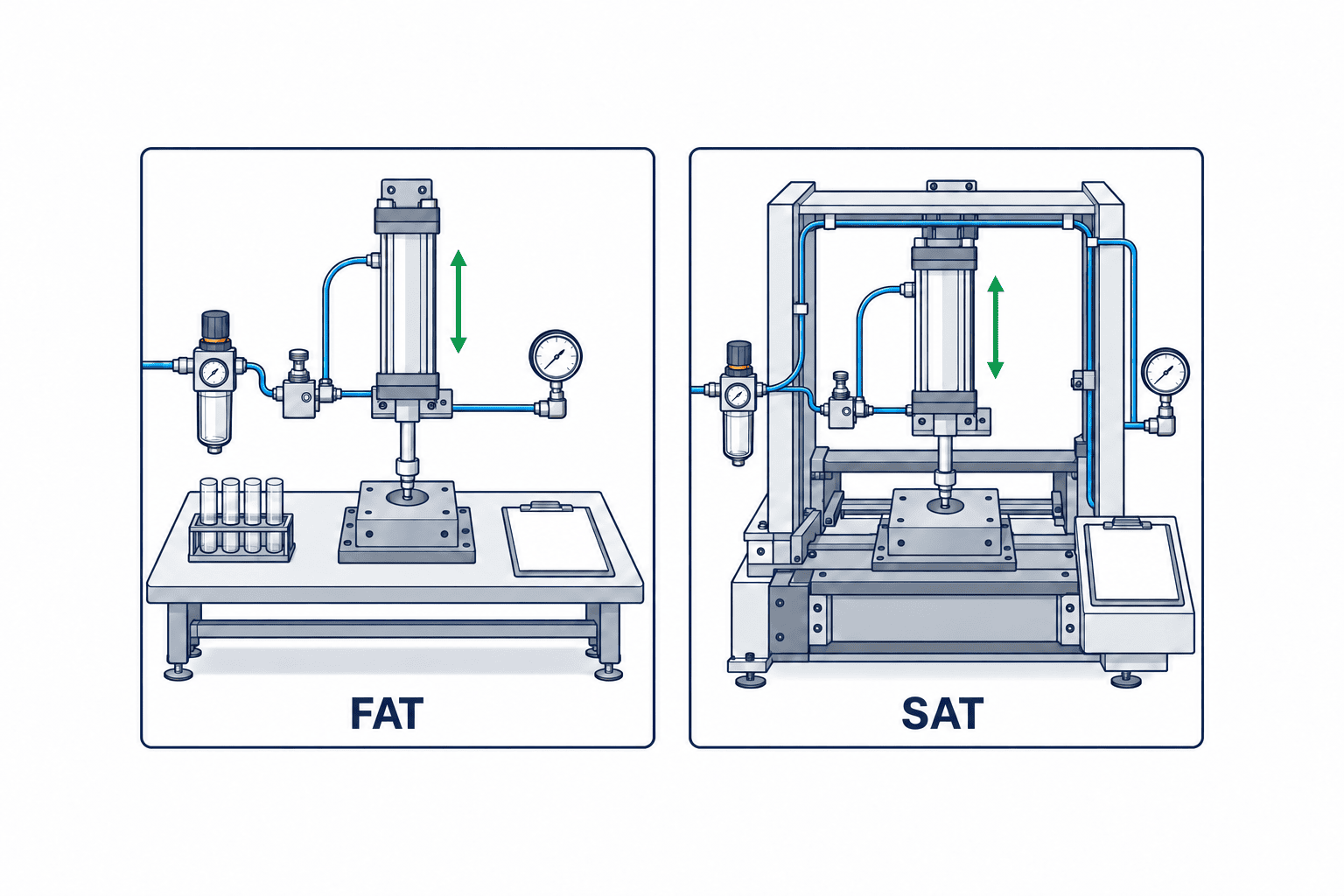
Separate what is known from what cannot be confirmed until SAT. If FAT cannot reproduce the installed tube length, a factory acceptance result must not be described as proof of final on-site speed. Agree who will decide the cost and schedule of reselection, repiping or controls changes if the installed machine misses tolerance. When FAT and SAT conditions do match, retain the test as a basis for a future identical machine. Save workpiece orientation and pressure with each time value so later projects do not reuse a number under different conditions.
Include installation and surrounding components in the specification
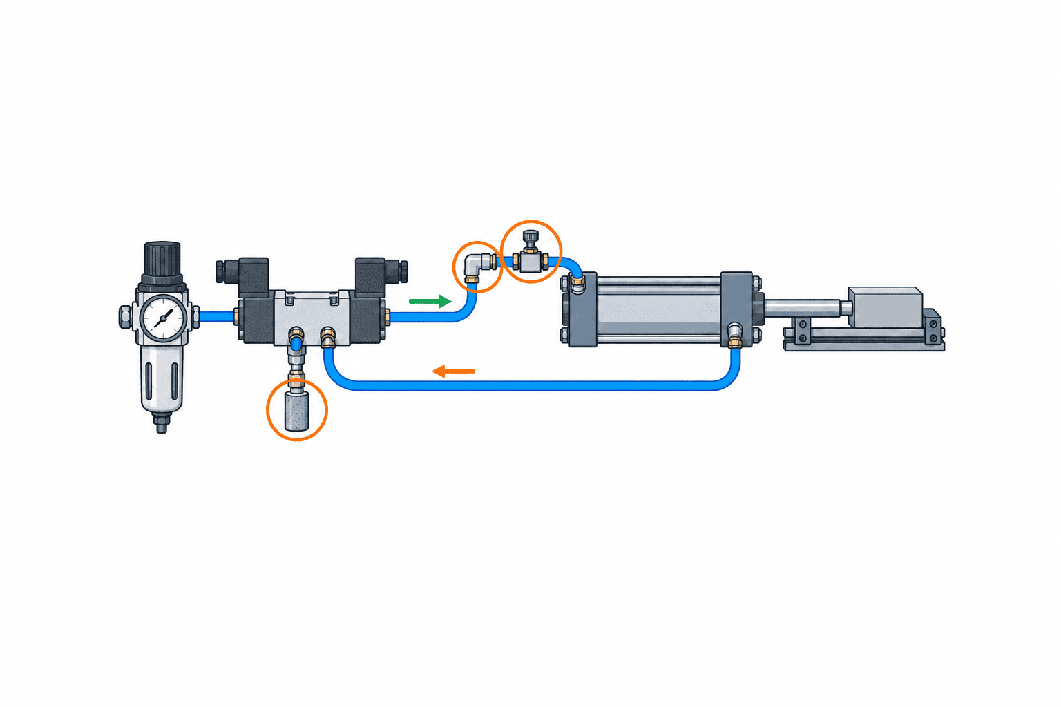
Mounting at a cylinder port and mounting in-line can change the air volume between the controller and the actuator. Show the chosen position in drawings and parts lists. Follow the specific product manual for flow direction, thread installation, seals, tube insertion and service access. Do not assume that an unchanged knob position will yield the same speed after relocating a controller.
Long or narrow tubing, small fittings and a restrictive or clogged silencer can all become the controlling restriction. If FAT uses short temporary tubing but SAT uses longer installed tubing, repeat the speed test. The same applies after changing a valve manifold or exhaust arrangement. “Free flow” through the check path also has finite resistance; inspect the product’s data for both directions. Pressure measurements at suitable points can help distinguish a restriction from an incorrectly oriented component, although permanent test points must be reviewed for leakage and extra air volume.
Actual Thai site conditions, not a countrywide assumption
For a hot, wet, washed-down or dusty installation, pass measured local conditions and cleaning practices to the supplier. Check operating temperature, media, materials, corrosion resistance and mounting protection against the selected part’s specifications. Thailand alone does not define one temperature or humidity. Maintenance should also check the availability of matching local tube and fitting sizes, spare models and a usable setting record. Air quality and contamination can influence throttles and check valves, so address filters and drying in the overall pneumatic design rather than masking a supply-air problem with a different controller.
Make the RFP a motion and test specification
Ask bidders for the part number, throttled direction, flow-curve test conditions, mounting method, compatible tubing, adjustment lock, environmental limits and spare part. Give them the movement and load cases against which their proposal will be tested. Prices only compare meaningfully if circuit scope, testing and maintenance provisions are equivalent.
| RFP field | Buyer requirement | Supplier response |
|---|---|---|
| Axis | Cylinder model, stroke, orientation and load range | Suitability and exclusions |
| Speed | Extension/retraction targets, tolerance and measurement points | Calculation or equivalent test basis |
| Circuit | Valve, pressure range, tube length/diameter and silencer | Circuit drawing and flow data |
| Control mode | Meter-out/in and independent direction control | Throttled direction for each model |
| Installation | Port or in-line position, space and environment | Dimensions, manual and replacement method |
| Safety | Responsibility for stop, restart and pressure-loss design | Risk assessment and separate components |
| Acceptance | FAT/SAT load cases, repetitions and records | Test plan and pass/fail sheet |
Meter-in and meter-out throttle different flow directions. Compare the configuration and usable range needed by the circuit, not merely the cheapest component. Mechanical design owns load and endpoint contact; electrical design owns valve commands and interlocks; pneumatic design owns pressure and residual air; maintenance owns replacement and readjustment. Name the person or organization that records each acceptance test.
FAT: verify motion, repeatability and recovery
FAT should use production-equivalent piping, silencer and load where feasible. Where production conditions cannot be reproduced, mark that item as unverified and carry its criterion to SAT. Confirm the part number and flow direction against the drawing. Record pressure, load, workpiece position and guide condition. Take repeated extension and retraction times between stated measurement points. Check whether target speed can be set and remains within tolerance after locking. Observe endpoint impact, workpiece shift and interference. Repeat at the allowed pressure and load limits. Finally, test the approved air-loss and restart sequence according to the risk assessment.
Acceptance limits must come from the machine requirement; there is no universal stroke time for a controller. A PLC timer from output ON to an end sensor includes valve response and sensor position, so define exactly what is being measured. Video or displacement evidence beside the PLC log makes deviations easier to explain.
SAT: remeasure after installation
SAT covers the installed machine with its actual tube lengths, pressure variation, valve position, silencer, workpiece and guide friction. Use the FAT setting as a starting reference, repeat the agreed tests and record adjustments. A large difference needs diagnosis; simply rewriting the setting value hides the reason. Keep the part model and identifier, location, controlled direction, locked setting, measured timing, load, pressure, date and tester in the maintenance record. Recheck motion even if a replacement controller is returned to the same knob position.
| Symptom | Check first | Decision |
|---|---|---|
| Too slow fully open | Pressure, valve, silencer, fitting, tube and load | Inspect the complete circuit before upsizing one part |
| Small turn causes a speed jump | Low-flow characteristic, size and lock | Select for the useful adjustment region |
| Extend and retract differ | Exhausting port, two settings and rod-side area | Measure each direction separately |
| Load changes motion | Orientation, gravity, friction, guide and pressure | Review motion and safety design |
| Restart causes a jump | Residual pressure, repressurization, valve and holding device | Prioritize stop/restart risk assessment |
Run a controlled comparison before changing control mode
For an existing machine, preserve baseline measurements before replacing a meter-in controller with a meter-out model or vice versa. Record extension and retraction time, workpiece displacement, impact and supply pressure with normal and reduced allowed pressure. Compare the manufacturer-approved circuits under the same load and measurement method. Changing the exhaust restriction may improve one stroke but affect back pressure and the return stroke. Record both the improvement and any deterioration. After choosing a circuit, revise drawings, parts lists, settings and replacement instructions together.
A faster cylinder does not always improve line throughput
Sensor confirmation, gripping, vacuum establishment, robot readiness and downstream permission may dominate the cycle. Saving 0.1 s on one stroke does not improve line capacity if another operation remains the bottleneck. Higher speed may also increase workpiece shake and impact. Evaluate axis time, machine cycle, product quality and maintenance separately. In some machines, sequencing or piping matters more than a larger valve; decide from measurements rather than a generic claim.
Hand over the reason for each setting
The maintenance instruction should say which load and stroke-time requirement a setting satisfied, not just “three turns.” Include safe isolation and residual-pressure steps from the machine procedure, model verification, leak check, gradual low-speed readjustment, motion measurement and approved restart test. Fix throttled direction in the spare part record as well as thread and tube sizes. Similar-looking meter-in and meter-out parts are not interchangeable. Label the physical adjustment with “EXTEND” or “RETRACT” where useful and map it to ports on the drawing.
Compare local spare availability, replacement time, compatible fittings and technical support when buying for Thailand. A lower unit price can be offset by repiping and downtime. An indicator offers little benefit if the target operating point lies at the extreme edge of its adjustment range. Quote the valve, fittings, brackets, installation, tests, spares and post-replacement setup separately; calculate actual cost for the specific machine.
Related reading and FAQ
If the cylinder bore or pneumatic-versus-electric choice is still open, start with our air-cylinder selection guide. For valve ports and PLC connections, read the pneumatic solenoid-valve guide alongside this article so the exhaust path is not overlooked.
Is meter-out always stable?
No. It is a useful default candidate, but actuator design, load direction, guide friction, pressure and piping can alter the result. Check the manufacturer’s circuit example and measure both strokes under load. Meter-out does not replace holding or a safety stop.
Can stroke time alone determine the required flow rating?
No. Stroke time gives an average travel speed. Cylinder and rod dimensions, pressure, air compressibility and circuit restrictions are also needed. Compare catalog ratings only with their test conditions and verify on the machine.
Can an in-line and a port-mounted controller share a setting?
Not as a general rule. Relocation changes piping volume and may change motion. Remeasure after installation changes.
Does locking the knob replace FAT/SAT?
No. Locking limits accidental adjustment; it does not prove stroke speed or restart behavior. Record both the setting and measured motion.
Conclusion
Pneumatic speed controller selection joins the throttled direction, separate load cases for extension and retraction, the entire air path, adjustment resolution and stop/restart behavior in one specification. Compare flow values using their stated units and test conditions. Prove the proposed circuit at FAT and remeasure it after installation at SAT. Treat vertical load holding and safety stops as separate risk-assessed design requirements.
If a cylinder on your Thai production line changes speed with the load, or you are preparing an RFP for a new machine, the current cylinder, valve and piping details are enough to start a useful discussion. Contact TOMAS TECH while requirements are still being defined.


