


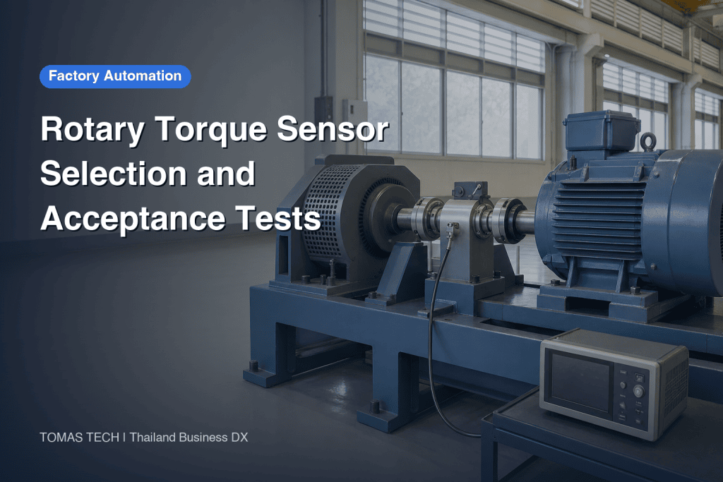
Choosing a rotating torque sensor from its rated torque alone is unsafe. For a sensor installed in a drive shaft, the specification must cover normal load, start and stop peaks, speed, side loads caused by misalignment, the event duration to be observed, and calibration scope. This guide helps engineers in Thai factories compare candidates, prepare an RFP, and define factory and site acceptance tests (FAT and SAT) for motors, gearboxes, assembly equipment and conveyors.
Start with the decision the torque reading will support
A development test bench and a production line need different measurement systems even when they measure the same shaft. A bench may need to preserve short transients. An inline system must also support uptime, maintenance access, vibration and contamination resistance, and PLC integration. Requirements differ again when the value decides product acceptance rather than merely indicating a maintenance trend. Write one sentence that identifies the shaft, operating mode, and decision to be made. “Measure torque” is too vague for a purchase order.
For gearbox efficiency, acquire input and output torque with speed on a common time base and hold test conditions constant. For fastening, inspect the torque peak in relation to angle. For a mixer, track steady load and abnormal peaks as viscosity changes. If the goal is machinery protection, distinguish the sensor’s own overload limit from the setting of a torque limiter. A torque sensor is not a protective device.
Show the measurement location on a drawing
Mark the proposed position on a shaft layout showing motor, bearings, couplings, driven machine and guarding. Check shaft and connection geometry as well as removal clearance, added rotating inertia, bearing span and the stationary cable path. Adding a sensor and couplings may alter shaft length, stiffness and natural frequencies. At high speed, critical-speed analysis can be necessary. HBK’s selection guide includes rotational effects, critical speed and extraneous loads among the dynamic issues to consider. Reviewing the mechanical drawing early avoids buying a sensor that physically cannot be installed. HBK selection guide
Separate sensor mechanics from signal transmission
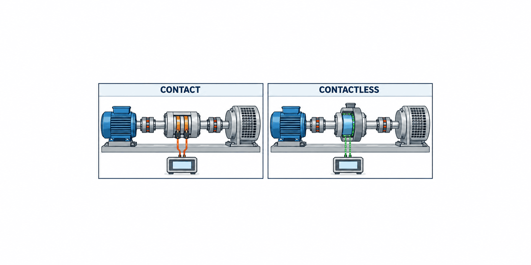
A rotary transducer measures torsion in a rotating shaft. A reaction transducer measures torque transmitted to a stationary mount, such as a motor housing. Both are useful, but they have different mounting, bandwidth and calibration conditions. Rotary designs also differ in how power and signals cross the rotating interface. Interface describes slip rings, rotary transformers, rotating electronics and radio telemetry. Here “contactless” normally describes transfer between rotor and stator; torque still passes mechanically through the shaft. Interface Torque Measurement Primer
| Approach | Questions for procurement | Potential fit |
|---|---|---|
| Contact transmission, including slip rings | Brush wear and replacement, cleaning, noise, rated speed | Limited-duty tests with planned maintenance |
| Contactless power and signal transfer | Rotor–stator clearance, electromagnetic environment, outputs, spare parts | Continuous or fast rotation, depending on model |
| Reaction transducer | Mount stiffness and torque load path | A design that does not require inline shaft insertion |
Contact transmission is not inherently the wrong choice. Existing mV/V instruments, budget and short tests may favor it. Interface says slip-ring sensors are usually not recommended for continuous or high-speed operation because brush wear produces dust and signal noise, and periodic cleaning and replacement are needed. Plan those tasks into line downtime or compare life-cycle cost with a contactless design. Conversely, “contactless” does not mean maintenance-free: check bearings, stator restraints, connectors and calibration for the proposed model.
For applications involving linear motion rather than a rotary shaft, see our electric-cylinder selection guide. Shaft torque and linear thrust cannot be treated as the same quantity without examining transmission geometry and efficiency.
Size the range for steady load, transient peak and usable resolution
Two common mistakes are sizing only for a low normal torque and oversizing so heavily that the useful low-load signal is lost. Record minimum, typical and maximum torque for normal operation, then consider startup, shutdown, rapid reversal, jamming, emergency stop and manual setup separately. Decide whether the peak must be measured accurately or merely survived. HBK notes that a short spike can damage a sensor without appearing in recorded data if response is too slow. Rated torque, maximum service torque and ultimate limits are different specifications and vary by model. HBK selection paper
In the RFP, state normal torque, expected peak, peak duration and whether torque reverses. If the peak is unknown, use temporary measurement or a justified upper-bound estimate before fixing a safety margin. Do not substitute a generic overload percentage for a model data sheet. A very large full-scale range can make low-torque signal-to-noise ratio and resolution inadequate. Request the uncertainty at the minimum operating point as well as at rated torque.
Read accuracy terms carefully. A percentage of full scale is not a percentage of reading, especially at the bottom of the range. Compare linearity, hysteresis, repeatability, temperature effect and zero shift using the same definitions. An isolated claim of “0.1% accuracy” is not a complete specification. HBK distinguishes nominal torque from maximum service torque, where declared measurement-property limits may no longer hold. The actual data sheet and calibration report should determine acceptability. HBK glossary
When two ranges may help
A machine with a large startup transient but small normal load may be difficult to cover with one range. Compare a dual-range model, exchangeable sensors on a bench, or a different measurement location. Two ranges do not automatically have equal uncertainty. Specify changeover behavior, calibration for each range and handling of a lost signal. Include low- and high-range points in the acceptance record.
Account for axial force, radial force and bending during installation
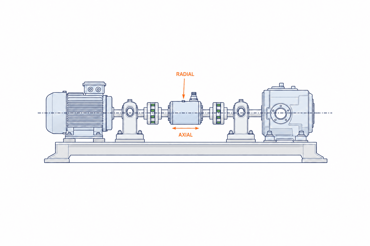
Loads other than torque arise from shaft misalignment, thermal growth, assembly tolerances, couplings, belts and gears. Do not compare axial force, radial force and bending moment with individual limits in isolation. HBK explains that permissible limits must be reduced when parasitic loads occur together. Ask the manufacturer for the permitted combination and the effect on measured torque. Even if the torque display appears normal, an unsupported side load may shorten life or distort the reading. HBK glossary
Select couplings to reduce the effects of residual misalignment. HBK states that parallel radial offset creates radial force and bending; angular offset creates bending; axial offset creates axial force and bending. Flexible couplings therefore do not eliminate the need for alignment. Check cold and operating-temperature positions, support stiffness and vibration. A fixture that worked on a bench can behave differently on a production floor exposed to heat, washdown and neighboring machinery. HBK coupling guide
State alignment tolerance for the entire assembly, including sensor and bearings, rather than copying a coupling catalogue value. Confirm that the bearing layout does not pass unintended force through the sensor, that the stator restraint does not pull it out of position, and that connectors remain accessible behind guards. Kistler’s rotating-shaft information likewise calls for accurate alignment even with flexible couplings. Record the as-installed alignment using the supplier’s recommended method. Kistler shaft sensor
Check the space required for retrofits
Measure the actual machine, not just its old drawing. List sensor and coupling lengths, extraction clearance, permitted shaft machining, guarding interference and cable bend radius. If the motor or gearbox must move, include machining, realignment and downtime in the quotation. Separate signal wiring from inverter power cabling according to the vendor’s instructions. A sensor that fits on paper but cannot be removed for service is a poor installation. HBK’s installation guide treats handling, driveline design, alignment, wiring and electrical setup as related tasks. HBK installation guide
Specify sampling from the event you need to see
Sampling rate alone does not ensure that a transient is recorded. Review mechanical response, sensor filtering, telemetry, converter bandwidth, DAQ sampling, PLC scan time and any data decimation as one chain. Define the shortest event, relevant frequency content, acceptable amplitude and phase errors, and required stored output. Interface recommends checking measurement bandwidth or sampling rate in rotary-transducer data sheets. Interface primer
The Nyquist condition requires sampling above twice the highest frequency of interest, but it is not itself a guarantee of adequate waveform accuracy. Leave engineering margin for anti-alias filters, peak capture, synchronization and storage. A one-second average used for condition monitoring cannot also describe a short fastening pulse. Decide whether operators need a complete waveform, peak hold, or interval statistics, and confirm the actual saved file at FAT.
When mechanical power is inferred from torque and rotational speed, align timestamps. A sensor may also output angle or speed, but resolution and delay differ by model. Kistler describes contactless power and signal transfer and optional speed or angle measurement for certain shaft sensors; those features must not be assumed for every model. Treat the PLC trend and the high-rate DAQ record as separate products while giving relevant events a shared time reference. Kistler shaft sensor
Distinguish sensor calibration from the complete measurement chain
A calibration certificate is useful only when its scope matches the application. Was only the transducer calibrated, or were amplifier, converter, cable, display and DAQ verified together? Compare calibration points with the operating range, direction of torque, temperature needs and range switching. Do not choose a universal recalibration interval without evidence. Combine the vendor’s guidance with use intensity, criticality, overload history and audit requirements. Add routine zero checks, comparison with a reference instrument, and recalibration after a damaging event.
Traceability is not a logo on a certificate. It concerns a documented measurement result, uncertainty, reference standards and an unbroken chain. NIST explicitly says that results, rather than instruments in the abstract, are traceable. Kistler describes traceable calibration of both reaction and rotating-shaft sensors; verify the scope, points, issuing laboratory, turnaround and cost for the selected model. Do not misapply ISO 6789 for hand torque tools as a blanket standard for a rotary transducer. NIST traceability FAQ / Kistler calibration
Check the certificate for model and serial number, units, date, references, points, direction, results and uncertainties, environmental conditions and issuing body. A generic data-sheet value is different from an actual certificate result. Recheck chain configuration if an amplifier is replaced. An internal functional check is useful, but whether it substitutes for external calibration depends on required accuracy and the quality system. Link calibration due dates and inspection history to the asset record.
Write different RFPs for bench and inline use
A bench emphasizes repeatable measurement and flexibility: fixture changes, speed sweeps, synchronized drive and load channels, waveform archives and planned stops for calibration. It also requires an assessment of shaft-system resonance. Specify an alignment procedure for each fixture change and include DAQ, software licensing, storage and fixtures in the quotation. If a wide range is necessary, compare sensor exchange or range switching under defined conditions.
Inline measurement adds availability and process safety. Decide what happens if the sensor fails: stop the line, hold quality decisions, or follow an approved alternative route. Define PLC output, loss-of-signal detection, communication-loss state, alarm hysteresis, retention, guarding, cleaning, dust and temperature. If the value accepts or rejects product, separate measurement-system variation from process variation. Do not transfer a bench data-sheet accuracy claim directly to the installed production line.
| Decision | Test bench | Production line |
|---|---|---|
| Main use | Understand behavior and compare designs | Monitor process, quality and maintenance |
| Key data | Synchronized waveform, peaks, speed and angle | Stable decisions, fault history and PLC state |
| Installation | Repeatability after fixture changes | Alignment stability and service access |
| Failure | Stop a test and assess data | Stop, isolate or use an approved alternate process |
| Acceptance | Known inputs and waveform repeatability | Process-specific decisions and fault behavior |
Twelve fields for a comparable torque-sensor RFP
Ask suppliers to answer the same fields: (1) objective and measurement point; (2) steady and transient torque and direction; (3) speed and acceleration; (4) uncertainty at the minimum usable point; (5) bandwidth and output data; (6) axial and radial forces and bending; (7) shaft, couplings and alignment; (8) environment and electromagnetic interference; (9) power, communications, PLC and DAQ; (10) calibration and recalibration; (11) spare parts, downtime and warranty; and (12) FAT/SAT responsibilities and pass criteria. Explain why any item is genuinely inapplicable.
Require data-sheet references, a configuration and mounting drawing, lead time and exclusions instead of a bare “compliant” answer. Separate the transducer, amplifier, couplings, cables, converter, software, installation and calibration into quoted lines. Local service, English or Thai procedures, and spare-part lead times can dominate life-cycle cost. Allocate responsibility for mechanical integration before orders are placed.
If the transient peak is unknown, a vendor promise of “safe operation” is insufficient. Ask the machine supplier and sensor supplier to document assumptions and missing values, and plan how to bound the peak before FAT. Shaft bearings, couplings, critical speed and guarding cannot be determined from the sensor sheet alone. Attach the machine layout and operating states so competing proposals are normalized to the same requirements.
FAT checks the specified system and failure behavior
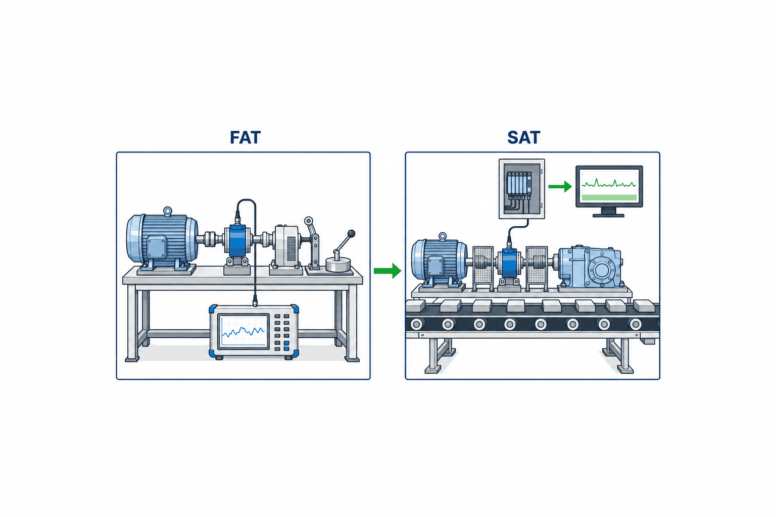
At factory acceptance, match the actual model, serial number, range, output, certificate, software version and accessories to the RFP. Apply known reference inputs at multiple points, including zero and both directions when relevant. Check range switching, speed input, scaling, timestamps and stored files. For transient requirements, record a representative event through the full sensor-to-DAQ chain under the agreed bandwidth and filter settings. Repeating a catalogue accuracy figure in a report is not FAT evidence.
Simulate communication loss, sensor power loss, threshold exceedance, stopped or reverse rotation, and restart. Check the action associated with each PLC alarm, not just the alarm bit. If the signal participates in a safety function, a qualified safety designer must approve that use; ordinary measurement capability alone is insufficient. Every FAT item needs a criterion, measured result, file reference, witness and retest rule. Document any item deferred to SAT and the conditions for provisional acceptance.
SAT verifies the installed drive train
Site acceptance is not a second copy of FAT. Verify actual alignment, couplings, bearings, rotation direction, cable routing, grounding, inverter noise, temperature and guards. Begin with safe low-speed operation and watch for sound, vibration, heating and zero drift before reaching representative duty. If a waveform degrades only on site, investigate parasitic loads, resonance, wiring, filters and PLC acquisition in an orderly sequence. Define who authorizes a stop, realignment and restart.
For production decisions, test good, boundary and deliberately abnormal samples. Look beyond short-run agreement to shifts in temperature, shift, speed and load. If necessary compare a reference device and verify that records connect the value to product, lot and time. When product variation and measurement variation cannot be distinguished, analyze the measurement system and stabilize test conditions before release. Collect final settings, calibration and alignment records, sample waveforms, fault procedures and spare-part lists at handover.
Compare the full cost, then choose
The purchase price excludes couplings, shaft work, cabinet changes, DAQ, software, calibration, spares, installation and downtime. Contact transfer brings brush maintenance; contactless transfer has model-specific electronics and mounting demands. Neither means zero upkeep. Compare total ownership cost at the same duty cycle and separately assess uncertainty and the cost of line stoppage. Where a single failure can halt a line, define replacement time and spare strategy before purchase.
A short pilot on the real shaft can reveal installation effort, noise and service access that a catalogue does not show. Run candidate sensors under the same waveform, speed and temperature conditions. A pilot cannot establish long-term reliability by itself, so distinguish performance verified at FAT/SAT from performance monitored after release.
Frequently asked questions
Is contactless always the best rotating torque sensor choice?
No. It is attractive for continuous or fast rotation when brush wear matters, but compare accuracy, bandwidth, outputs, space, maintenance and price. A contact-transmission device may suit a short bench test or existing instrumentation. Specify duty and data quality before choosing the method.
Does a flexible coupling remove the need to align a rotating torque sensor?
No. A coupling reduces the consequences of residual offset but does not eliminate parasitic forces. Check the sensor–coupling combination, bearing layout, thermal growth and load limits, then record alignment and a low-speed trial after installation.
What sampling rate is required for torque measurement on a rotating shaft?
There is no universal number. Start from the shortest event and required waveform fidelity, then review sensor and converter bandwidth, filters, DAQ rate and stored-data format. Ask the supplier to show an example of the final saved output.
Does a calibration certificate guarantee inline decision accuracy?
No. Check its range and uncertainty alongside amplifier and DAQ settings, parasitic installation loads, temperature and decision logic. Verify the complete installed chain at SAT.
Where should a torque-sensor RFP, FAT and SAT begin?
Begin with the decision, shaft drawing and operating-state table of torque, speed and side loads. Turn that into comparable RFP fields. Verify the instrument and signal at FAT and the installed drive train and control response at SAT.
Conclusion
Selecting a rotating torque sensor requires more than rated torque. Connect the measurement decision to steady and peak load, contact or contactless signal transfer, axial and radial parasitic force, couplings and alignment, chain bandwidth, calibration and the difference between bench and inline operation. Make the RFP comparable across vendors, verify instruments and waveforms at FAT, and confirm the installed machine at SAT. Final limits must come from the current data sheet for the specific model and the actual machine conditions.
If you are still choosing a measurement location, range or FAT/SAT checklist, contact TOMAS TECH. We can help define the mechanical, control and data requirements from your machine drawing and target event.


