


The difficulty in selecting vacuum suction pads lies not in the catalog-listed suction force, but in the actual condition of the surface in contact with the workpiece. Even parts with the same mass will behave differently—whether it’s a smooth metal plate, textured resin molding, or a powdered bag, the air leakage and release characteristics differ. When outsourcing robot transport or pick processes at a Thai factory, you should define not just the pad diameter for quoting, but also workpiece variation, contact marks, and actual transport attitude. This article focuses on the “contact interface” of pads, covering material, shape, arrangement, on-site trials, and confirmation steps from RFP to FAT/SAT.
Selection of Vacuum Suction Pads Starts with “Where to Touch,” Not Just “What to Hold”
When selecting a robot hand, one compares mechanisms such as mechanical, vacuum, and soft grippers. But even after choosing vacuum type, it is the pad’s lip that actually holds the workpiece. Schmalz positions suction pads as parts connecting the workpiece to the handling device, and lists material, dimensions, surface, temperature, acceleration, and transport attitude as selection items. In other words, increasing the pump or ejector’s capacity alone will not fix interface mismatches.
Begin by gathering not only “easy-to-pick” representative parts but also the “difficult ones.” Record dimensions, weight, center of gravity, possible suction surfaces, flatness, roughness, irregularity, oil, powder/dust, moisture, temperature, flexibility, surface finish, print location, and allowed contact marks. If these vary by lot, supplier, or production conditions, indicate their ranges. In practice, combinations of the heaviest, most warped, or roughest parts tend to determine the design rather than the lightest. However, do not collapse these into an “all-worst” item: maximum weight and maximum leakage may occur in different varieties, so split test samples accordingly.
Potential suction surfaces are determined not by whether they “look flat” but by where the pad’s lip can maintain continuous all-around contact. Overlay holes, grooves, embossing, burrs, steps, seals, label edges, creases, and curvature changes on drawings. Thin sheets or films can deform upon suction, causing the lip to rise or inadvertently picking up two at once. Even transparent trays can’t be judged by outline alone—check ribs and gate traces in person.
The scope of suction pad review is one level below what is outlined in Robot Hand and Gripper Selection. This article deals not with brand comparisons of vacuum sources, but with the conditions under which pad–workpiece contact is established.
How to Choose between Flat, Bellows, and Special Lip Types
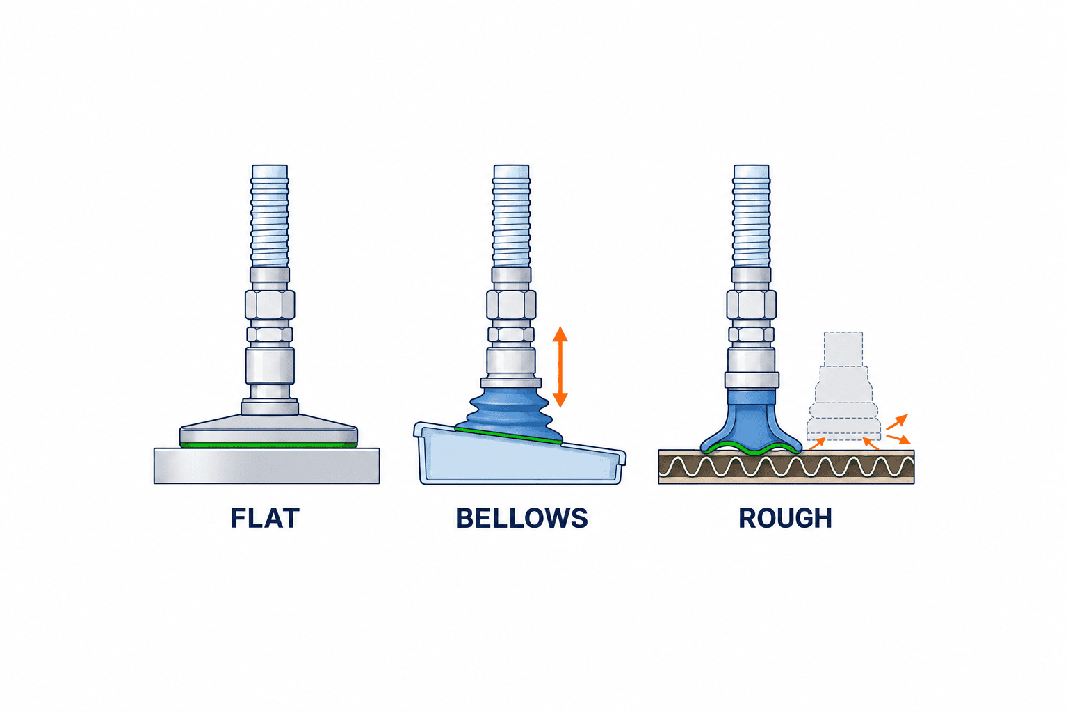
According to selection guides from Schmalz and SMC, flat pads are mainly for planar, relatively rigid surfaces, while bellows types are for absorbing differences in height or tilt. However, simply saying “use bellows for steps” is simplistic—pad collapse and return time may then limit the cycle. Flat types tend to have smaller internal volume, evacuate faster, but have a narrower tolerance for contact height. Bellows types offer compliance but require attention to side load, sway, positioning accuracy, and return upon detachment.
| Contact Condition | Primary Choice | What to Check in Real Life |
|---|
Smooth, hard horizontal surface | Flat/low lip | Lip seal continuity, contact marks, slip during acceleration |
Multiple workpieces at differing heights | Bellows, or buffered flat pad | Compression, tilt, seating delay, sway |
Light curved/uneven surfaces | Compliant lip | Match of curvature to lip perimeter, local leakage |
Rough, porous, cardboard | Specialized lip or foam candidate | Leakage flow, dust, repeated degradation |
Thin film, bag | Small diameter, multiple points, shape retention as needed | Wrinkles, double picking, residual adhesion, scratches |
This table does not specify products. Piab states that rough, textured, or corrugated surfaces increase perimeter leakage making stable suction more difficult. Therefore, shape selection is based not on “did it work once” but on whether workpieces with variation can be handled repeatedly at the required speed. If flat pads leak on rough cardboard, review the lip design and contact position before raising the vacuum setting.
When using multiple pads on a single workpiece, not all will seat simultaneously. Warpage, table flatness, robot posture, and pipe length can mean some pads seal first while others float. If a floating pad disrupts a shared vacuum line, design must include zoning, check valves, flow control, and position adjustment. More pads do not always equal safety; increasing pad count also increases management of contact variation.
Material Selection Narrows by Workpiece Contamination, Wear, and Temperature
Material name alone does not determine superiority. Schmalz lists wear resistance, oil resistance, and food suitability as material selection criteria; SMC adds consideration of effects on the workpiece, surrounding environment, and conductivity. NBR, silicone, polyurethane, EPDM, etc., are candidate starting points; check manufacturer/grade specs, use temperature, chemical compatibility, and food contact certifications.
Color transfer from black rubber to white resin, possible silicone effects in later painting or bonding, scratches on soft film, and lip wear due to sharp edges should all be separate pass/fail items from suction strength. For electronic components where conductivity/ESD measures are crucial, check not only pad material but grounding path of the joint and machine. For food/medical use, don’t assume suitability based on color or material name—link approved part numbers to documentation.
For high-temperature workpieces, differentiate the post-removal peak temperature from time spent in contact during cycle stops. If material is chosen only for short-term peaks, you may overlook deformation or hardening during long-term stops. State oil, mold release, and cleaning agent presence—not just presence/absence, but also concentration, application location, and cleaning frequency. Don’t decide by broad tropics-related generalizations (such as “hot, humid Thailand”); present measured local conditions and real workpieces.
Interchangeability is part of material selection too. Pads are consumables, and sealing changes with wear or hardening. Factor part numbers, replacement units, lead time, local stock, tool needs, and re-positioning after replacement into your estimate. Designing a system for planned, consistent replacement is often easier to manage than simply chasing the “most durable-looking” material.
Calculating Suction Force is Only the Start—Leakage and Side Loads Require Measurement
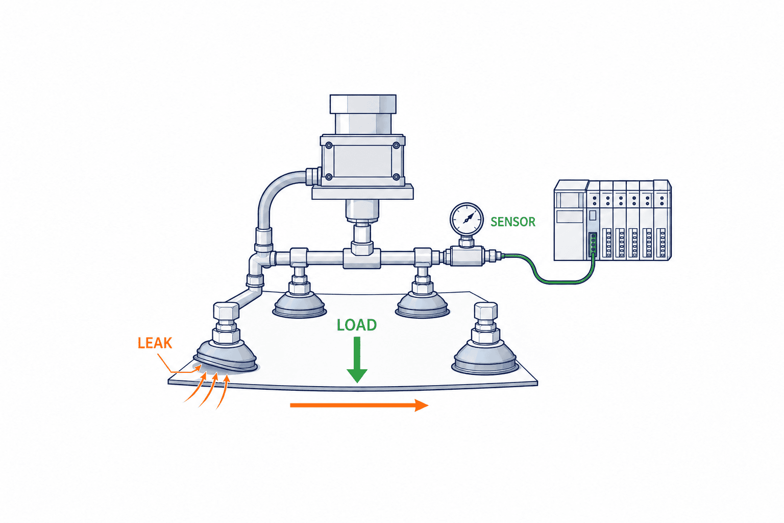
The basic vacuum suction formula is F = Δp × A. F is the theoretical holding force perpendicular to the surface, Δp is the pressure differential between atmosphere and pad, and A is effective suction area. Schmalz lists not only this theoretical value, but also shear force (in-plane), peel-off force, curvature, stroke, and internal volume separately. Crucially, catalog “suction force” does not equal usable force in all directions and conditions.
For example, assuming a perfect 30 mm diameter circle and 60 kPa pressure differential, nominal area is about 707 mm², and the calculated vertical force about 42 N. But this is just a geometric illustration—in reality, effective area changes with lip shape, and air leakage from the workpiece reduces pressure differential. It’s dangerous to translate 42 N directly as “can carry about 4 kg.” Also evaluate acceleration, tilt, slippage, offset, suction misalignment, piping loss, and safety margin separately. Even manufacturer data clarify that catalog values are under specific vacuum—do not include safety factors.
Calculate in this order: derive necessary force from workpiece mass, determine load direction from transport attitude and max acceleration/deceleration, estimate each pad’s share per layout, measure actual vacuum, leakage, and slippage with real workpieces, then verify operational conditions and margin. If the workpiece is tilted, distance from suction point to center of gravity creates a moment. Even with symmetrical four-point layouts, curved workpieces rarely distribute load equally. Confirm how few points can really hold, or what happens if one branch leaks.
Leakage cannot be explained by “what is the vacuum level?”. Record achieved vacuum, rise time, in-hold variation, and recovery after drop, all from the same sensor point and flow setup. A shared manifold pressure can hide local leakage at a single pad. In trials, if needed, log branch pipe pressure or flow, work detect signals, robot position, and cycle result chronologically. Set vacuum threshold and timeout based on actual test distributions, and maintain these after product changes.
SMC’s FAQ advises: calculate theoretical lift, then test with actual equipment for go/no-go decisions. “We’ve calculated, so we can skip real trials” is not their advised approach. Note assumed workpiece states in calculation sheets, and temperature, dirt, part number, and cycle speed in test data.
Selection Tests Should Not End with Only Good Samples
The goal is not to record only successful demos, but to find failure boundaries. First, classify workpieces by type, lot, surface state, and deformation. Next, for each pad candidate, lock suction point, compression, vacuum threshold, wait time, route, and accel/decel for comparison. Varying several at once makes it impossible to tell what worked. Note failure types: did not pick up, dropped after lifting, slipped in transfer, hung on release, double-pick, left marks, or left position offsets—each calls for a different remedy.
If candidate A is fast on average but repeatedly times out when handling dirty workpieces, it is weak as a mass-production option. If candidate B is slower to suction but stable under worst conditions and easy to replace, overall downtime may remain low. Don’t base this evaluation only on hardware cost; include pad change rates, cleaning, local inventory, air consumption, retry, and scrap. Decide figures by in-factory measurement—don’t copy another company’s success rates as your own guarantees.
Validate at minimum in these four steps: (1) Check seating and leakage in static condition. (2) Check dynamic transport at planned speeds and position changes. (3) Run boundary tests with contamination, warpage, temperature, and supply variation. (4) Test repeatability after cleaning/replacement. In all, do not pass based only on “didn’t drop.” Log time to suction complete, vacuum pattern, position accuracy, contact marks, retries, and operator recovery steps.
If the feeder-side has large positional variation, don’t try to compensate fully on the pad side. Reconsider guides, stoppers, alignment mechanisms, and detection. It’s often cheaper to stabilize supply orientation than to add expensive compliance mechanisms. Conversely, if supply variation is unavoidable, spell out its range in the RFP to define design responsibility for pads, buffer, and sensors.
What “Contact Interface” Requirements Should Be in the RFP?
Case 1: Oily Pressed Parts
In thin stamped steel after pressing, oil film thickness and spread can vary even for the same part number. If you pick a pad based on dry prototypes alone, slippage or double picking may occur in volume production. First fix possible contact regions in drawings, eliminating areas near burrs and holes. Next, for dry, normal, and heavily oiled samples, run identical-path tests from pick through transport, attitude change, and release. To distinguish whether failure is due to oil or to lip lift from bending, log suction position and vacuum profile.
When changing pad materials during testing, avoid changing shape or diameter simultaneously. Changing one factor at a time will help separate oil resistance, lip compliance, and slippage effects. For final candidates, have the quality team assess surface scratches and oil transfer. If holding is possible but downstream washing or painting is affected, disqualify that candidate. Separately evaluate recovery after long stops or emergency stops while holding.
Case 2: Corrugated Cardboard Carton Tops
Even if box size is identical, humidity, loading, carton tape, and lid creases all change the contact area. A single large-diameter pad at the box center might overlap tape edges or creases. While several small pads can better avoid such zones, seating variation per site increases. Specify not just number of pads but allowable tape position range, maximum box bulge, supply position, and box rotation. Adjust supply orientation on the conveyor if needed so the vacuum hand isn’t overloaded.
Cardboard leaks both from the surface and through material. Holding one box for a long time after successful pickup doesn’t check evacuation time or dust accumulation in rapid cycles or long runs. Compare new, used, wet, and dented boxes, and vacuum profile before/after filter cleaning. If relaxing sensor thresholds to increase success, specify how much margin for fall detection remains.
Case 3: Thin Edges of Formed Trays Only
With formed trays or blister packs, when contents, printing, seals, and steps must be avoided, only a narrow edge may be available for suction. Even if pad nominal diameter is small, lip outer diameter and contact width are separate—check that the contact ring fits the edge. If tray base sags and edge angles shift when lifted, static contact photos are not enough—shoot video of deformation and placement accuracy in transit.
Here, supporting jigs or distributing load across multiple points is sometimes more effective than stronger vacuum. Ensure the support doesn’t scratch the product or hinder cleaning, with approvals from quality/maintenance. If lip positions require adjustment for new variants, include scale, reproducibility, and error-proofing in acceptance specs.
An RFP stating only “vacuum suction hand, complete” is too broad. Test coverage and component composition will vary per vendor, making price comparison meaningless. At minimum, include the workpiece list, allowable and forbidden suction areas, weight and center of gravity, surface variations, supply state, transfer attitude, max cycle, cleaning schedule, contact marks, and dropped-work risk. Sample sets should include not only good parts but also most warped, roughest, dirty, and those showing seasonal or supplier variation.
| RFP Item | Specification | Acceptance Evidence |
|---|
Workpiece scope | All types, materials, surfaces, weights, variation range | Sample registry, test records |
Suction area | Allowable/forbidden areas, mark acceptance criteria | Position diagrams, appearance check photos |
Pad specs | Shape, material, part number, quantity, replacement method | Drawings, parts list, local stock |
Vacuum check | Sensor position, threshold, timeout, abnormal actions | Log data, PLC signal table |
Operation | Posture, accel, speed, cycle requirements | Test logs, video |
Maintenance | Cleaning, inspection, replacement schedules | Procedures, post-replacement retest log |
You don’t need to lock in manufacturer part numbers from the start, but you do need to specify material and dimensions for evaluation. If alternates are accepted, conditions should include lip design, material compatibility, and passing tests on actual workpieces—not just dimensional interchange. Quantities, sourcing, and consumption responsibility for spares must be clear.
When comparing multiple quotes, align the scope for design, testing, installation, acceptance, and maintenance as per Automation Quote Comparison Scope Standards. Even if pads are cheaper, if on-site testing, spares, sensors, or error-handling recapture costs are extra, total price may not be low.
What to Distinguish in FAT and SAT
Decide the Recording Format in Advance
Test records must enable later condition reproduction, not just a table marked “OK.” Link workpiece number, lot, pad part and run time, suction point, vacuum source setting, sensor point, threshold, robot program version, speed, temperature/humidity, tester, and failure details in a single register. Specify how and when to log vacuum profiles. If setting thresholds change by product, log old and new values, reasons, and signoff.
If the pad was changed during acceptance, you can’t meaningfully average success rates before and after. Either confirm post-wear performance or break up test sessions at replacement points. Ditto for lots: loading all easy lots dilutes failure rates where hard lots were less tested. Tabulate results by part/state, not just overall average. If some types were excluded from testing, record reason and plan for mass production handling.
Include Abnormal-Event Behavior in Pass/Fail
Define robot action for cases where vacuum sensor failed within allotted time—retry, or halt line? If vacuum is lost in transfer, check by which signal, where the stop occurs, and what steps operators take to recover. Power failure, air pressure drop, hose detachment, or missing pads are rare but serious. Handle within overall equipment safety and reflect in site retraining.
If pad wear is checked on scheduled inspection, avoid ambiguous “looks still usable” judgments. Specify objective signs—chipped lips, hardening, cracks, marks, vacuum time change—as criteria for replacement. Standardize post-replacement vacuum confirmations or short-batch test transport. For on-site equivalent pads, maintenance staff also need the acceptance-test standards, so sourcing doesn’t substitute just by dimension.
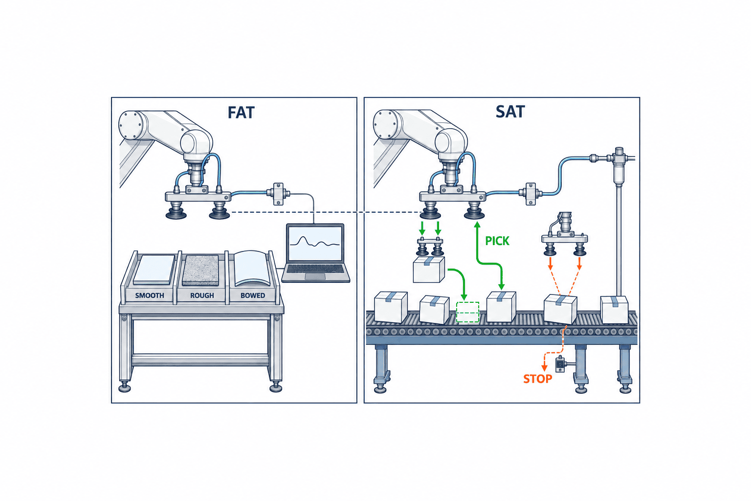
At FAT (factory acceptance test), check suction position, vacuum profile, in-transfer retention, drop, abnormal reset, with the agreed samples and test conditions. Log serial numbers for test pieces, include difficult workpieces. If you only search for “success settings” and reduce speed, you can’t validate contract performance. Record and judge pass/fail versus speed, acceleration, vacuum threshold, pad state, piping and sensor positions used.
At SAT (site acceptance test), add actual supply, factory air, pipe lengths, temperature/humidity, dust, operator, and setup change conditions. Even parts that passed FAT may fail more at site from supply shake or air pressure drift. If local conditions are changed, log reasons and differences from design. It’s also SAT scope to swap new pads or check post-cleaning threshold stability.
Pass/fail shouldn’t just be “N out of N passes.” Define results for each variant, failure modes, product damage, maximum suction time, recovery time, and safety status at error stops. If drop can hit workers or key equipment, assess loss-of-vacuum action, redundancy, and mechanical drop prevention as risk controls. Don’t conflate component-level suction success with full-equipment safety confirmation.
For gate acceptance responsibility and evidence management, also see Selecting Robot SIers in Thai Factories. Clarify beforehand who rules on pass/fail of actual trials, who preps workpiece samples, and who reevaluates for new variants to minimize disputes after handover.
Frequently Asked Questions
Is a larger pad diameter always safer?
Not necessarily. A larger diameter increases theoretical area, but any holes or steps in the contact region break the seal. For soft workpieces, deformation and marking increase; with multiple pads, layout flexibility may drop. Always measure effective area and vacuum, and check for transport attitude and workpiece impact.
Can bellows pads absorb all warping or height differences?
They function within limits, but involve trade-offs with stroke needed, sway, positioning, and evacuation time. Consider not just max warpage but its direction, difference at each suction point, and simultaneous multi-point seating. If needed, use buffers, separate vacuum circuits, or guides on the supply side.
Can you pick porous cardboard or rough resin?
It is possible, but you must test for lip leakage, leakage through the material, dust, or lot variation. Try dedicated shapes or foams, measure not just achieved vacuum but leak flow and suction time. If the product itself conducts air, simply using a larger “airtight” pad won’t solve the problem.
Should I choose NBR or silicone pad material?
It depends on application and manufacturer grade. List out actual requirements—oil, temperature, wear, color transfer, painting/bonding steps, and food contact—and compare specs and test results. Do not approve based on generalities like “silicone is good for heat” or “NBR is general-purpose.”
Can SAT in Thailand be skipped if FAT passes?
It should not be skipped. On-site supply position, piping, air, the environment, and operator setup alter performance. FAT checks in design conditions; SAT checks after installation. Using equal workpiece IDs, measurements, and pass criteria in both lets you track and explain any differences.
Three Changes to Watch For After Introduction
In the first few weeks after starting operation, do not judge solely by the pick failure rate. First, look at the distribution of vacuum attainment times. If the time gradually increases even for the same product type, suspect lip wear, filter clogging, pipe loosening, or changes in the workpiece surface. Second, check for misalignment at placement and the detachment time. Even if suction works, if the workpiece remains when placing or bounces at the moment of release, it will affect the quality of subsequent processes. Third, observe reproducibility during maintenance. If you need to adjust the suction position or sensor thresholds each time after pad replacement, it indicates a lack of standardization in parts and installation criteria.
These three metrics should be recorded by identifying the product type and lot. Even if the overall success rate is the same, deterioration may occur only for specific product types. If you link vacuum data and equipment stop logs, it becomes easier to distinguish whether the issue is with the pad itself, a change in supply orientation, or a change in the workpiece material. Also, determine the initial response when values fluctuate. Clearly define the range where operators can clean the pad surface and retest, where maintenance replaces parts, and where the quality department isolates the workpiece. If only the threshold is relaxed on the shop floor to keep operating, abnormalities may be missed.
Rather than simply determining pad lifespan by elapsed days, it may be more rational to combine the number of contacts, suction time, appearance, and vacuum waveform. However, if there are too many monitoring items, the system may not remain operational. First, identify one or two changes that led to defects or stoppages and reflect those items in the inspection form. When new product types are added later, do not reuse old thresholds—verify with the new product’s surface and transport conditions instead.
Summary
One-Page Order for Selection Reviews
In meetings, before comparing catalogs, it’s best to answer in this order: (1) Which kind, and exactly which surface, will be held? (2) How do those surfaces vary? (3) What counts as a failure? (4) Who approves results of on-site testing? For (1), list forbidden contact areas too. For (2), don’t just add drawing tolerances, but account for real-world dirt, warping, temperature, and lot variation. For (3), include not only drop but also offset, marks, double-pick, failure to release, cycle delay, and maintenance frequency. For (4), assign clear roles to quality, engineering, maintenance, and the SIer. Only then do candidate comparison tables become meaningful.
Comparison columns should go beyond “product name” and “nominal suction force”: fill out minimum suction surface size, lip OD, needed push-in, material compliance, vacuum dwell time, leakage variation, side load, contact mark, replacement time, sourcing, and spares costs under unified conditions. If unknowns remain at contract, specify who, when, and on which trial will confirm them. If ordering with untested ranges, link the unconfirmed scope to design change provisions, or dispute will arise later around cost and delivery.
Selection doesn’t end after mass production starts. If workpiece supplier, packaging, coating, or molding conditions change, update interface checks and retest if needed. If vacuum profile or pick failures shift, check not only the pad but also workpiece change, supply position, filter, piping, and sensors in order. Managing the interface as part of process conditions underpins stable operation.
Selecting a vacuum suction pad means defining the contact surface of the workpiece, narrowing down shape and material candidates, and verifying leakage, slippage, and contact marks with actual samples, calculation serving as only the starting point. RFPs should include boundary, not just representative items, and FAT/SAT tests should match conditions. By comparing not only unit price but retention margin, post-replacement consistency, and recovery from error, you build specs that survive mass production.
If you handle various workpiece surfaces and variants at your Thai factory and want to organize pad candidates or acceptance conditions, feel free to share your sample lists and current failure examples for discussion. Please contact us via Contact TOMAS TECH and share your target workpieces and process conditions.
References
- Schmalz: Selection Aid for Vacuum Suction Cups — Selection criteria: weight, surface, contamination, temperature, acceleration, transport attitude.
- Schmalz: Technical Data of Suction Cups — Differentiates vertical theoretical force, shear, volume, etc.
- Schmalz: Suction Cup Shapes — Characteristics of flat and bellows styles.
- Schmalz: Material Overview — Wear, oil resistance, environmental suitability.
- SMC: Vacuum Pad Model Selection — Technical materials on pad selection and practical verification.
- SMC: Vacuum Pad FAQ — Recommends practical suction tests after calculation.
- Piab: Suction Cups for Textured and Rough Surfaces — Leakage issues with rough/corrugated surfaces.


