


Introduction: You Chisel-Test Parts Every Day, but the Welds in Between Remain Unknown
This article is written for plant managers, production engineers, quality assurance and maintenance staff at factories in Thailand who are considering introducing spot welding monitoring. On many body-part and chassis-part lines, one to several parts are broken with a chisel every day to check the welds. But that only tells you about the welds on the parts you broke. Whether the welds on the hundreds or thousands of parts that ran before the next check were good is something nobody can explain without records.
A customer asks, “Please send us the weld current values for the parts that ran during this time window.” You open the welding controller screen, only to find the data has been overwritten and is gone. New EV parts bring more high-strength steel and coated steel sheet, and electrode tips wear faster than before. If these situations sound familiar, this article is for you.
Note that the scope here is monitoring the data of each resistance spot weld and linking that record to the part. Inspecting arc welding beads with cameras and AI is a different process and a different system; for that, see our article on AI quality inspection of weld beads.
Here is the conclusion up front. Spot welding monitoring is not about “adding equipment.” It is about first deciding which welds’ data you keep, against which part numbers, and for how many years. Judging from manufacturers’ announcements, many current welding controllers can already handle per-weld data such as current and weld time. The first things to do are these 3:
- Decide which welds to control (key welds)
- Collect data from your existing controllers and link it to part IDs
- Record tip dressing (reshaping the electrode tip) and electrode life
Upgrading to external monitors or adaptive control is something to consider afterwards, limited to the key welds. Also, destructive tests such as the peel test and chisel test do not go away when you introduce monitoring. Changing their frequency requires customer approval.
This article does not recommend or rank specific products. Product features are presented as manufacturers’ announcements. The cost-benefit analysis in the second half is a model calculation built on illustrative figures prepared for this article.
Why Thai Factories Should Revisit Spot Welding Monitoring Now
First, let us look at where Thai automotive production stands. Figures are given with their source and scope as published; we do not add them up or apply them to any particular company.
- According to the Federation of Thai Industries (FTI) announcement on September 28, 2026, four-wheel vehicle production in August 2026 was 124,646 units, up 10.9% year on year. Growth was led by passenger BEV production (up more than 77%) and pickups for export (up more than 18%).
- Cumulative production for January to July 2026 was 834,595 units, and July growth was reported to have been supported by BEV, PHEV and HEV production.
- On the other hand, according to a report on July production, FTI had earlier forecast full-year 2026 production to fall by 3.33%. June production was down 7.55% year on year, and month-to-month swings remain large.
- Full-year 2025 production was 1.455 million units (FTI announcement on January 28, 2026). Among passenger cars, ICE vehicles fell 29% year on year to about 248,000 units while BEVs more than doubled to 71,000 units, a major shift in the mix.
- Krungsri Research (August 3, 2026) projects 2026 to 2028 production to grow 0.5 to 1.5% per year, at 1.49 to 1.51 million units per year. The same report states that Japanese manufacturers account for an estimated 80% of domestic production capacity.
EV policy also matters to parts plants. According to the Thailand Board of Investment (BOI) announcement in December 2024, under the EV 3.5 scheme, 2 locally produced vehicles are required for every imported vehicle in 2026, and this ratio rises to 3 in 2027. Under the November 2025 revision, subsidy payments became directly tied to meeting local production targets, with reductions if targets are missed. As carmakers expand local production, launches of new materials and new part shapes will come to parts plants.
Near-term risks also need attention. According to a report on October 8, 2026, an embankment collapse caused flooding in Zones 7, 8 and 9 of the Amata City Chonburi industrial estate, and more than 10 automotive parts plants stopped operations. The impact was reported to fall mainly on Japanese companies, particularly Toyota, and industrial losses were put at about 6 billion baht as a provisional estimate. When equipment stops and is restarted, whether you have records showing that “we are welding under the same conditions as before the stoppage” affects shipping decisions after recovery.
On the people side, in May 2026 TWI Thailand and the Department of Skill Development (DSD) of the Thai Ministry of Labour signed a memorandum of understanding, starting a move to incorporate CSWIP welder certification into the national skill development framework. Systems for proving welding skills are taking shape, but for spot welding done in large volumes every day by robots and stationary machines, per-weld records carry weight as evidence of quality, in addition to personnel qualifications.
What Determines Spot Weld Quality, and Why You Cannot Know Without Breaking the Part
Spot welding (resistance spot welding) clamps overlapping steel sheets between upper and lower electrodes, applies force, passes a large current, and joins the sheets using the heat generated by electrical resistance at the contact area. The main factors that determine quality are these 4:
- Welding current: Determines the amount of heat. Both too high and too low lead to defects
- Weld time: How long the current flows. Even at the same current, heat input changes with time
- Electrode force: The force with which the electrodes press the sheets. It affects contact resistance and containment of the molten metal
- Electrode tip face diameter: The area through which current flows. As the tip wears and the face spreads, current density falls even at the same current
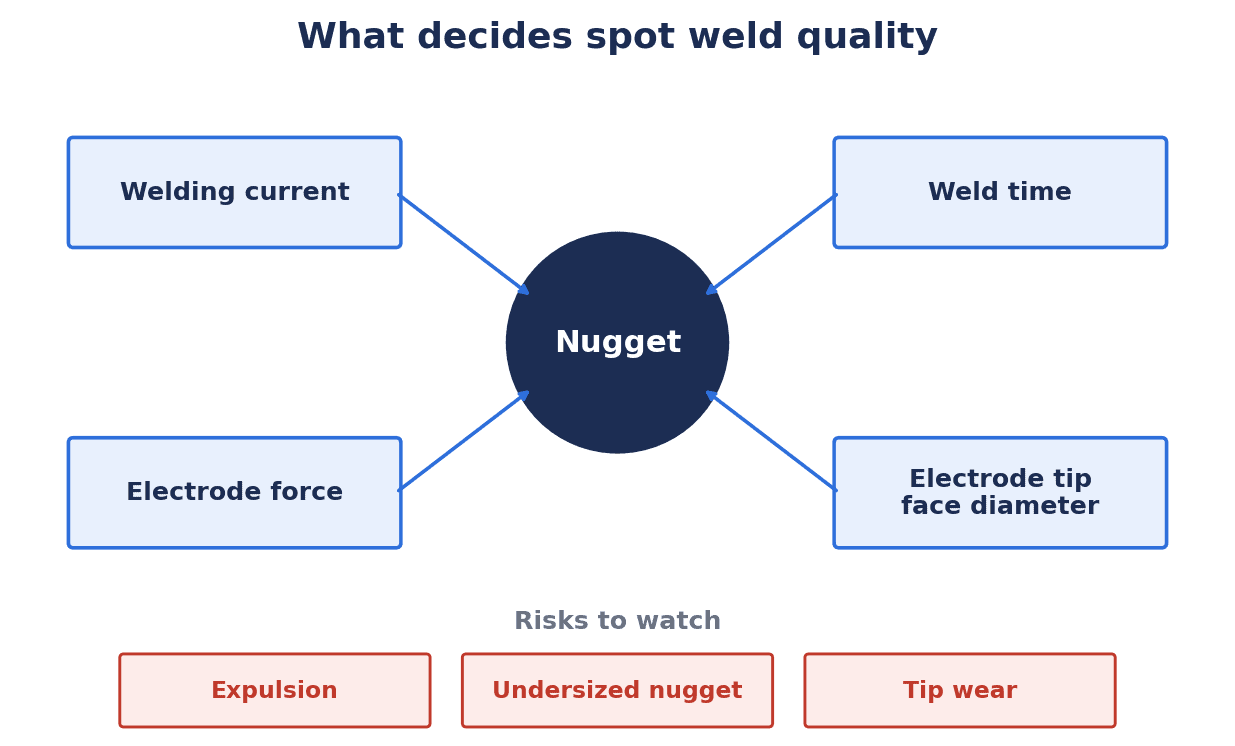
When these conditions are right, a nugget (the joint that has melted and solidified) forms between the sheets. If heat input is insufficient, the nugget becomes small and strength is not achieved. If heat input is too high or electrode force is insufficient, expulsion (ejection of molten metal) occurs, which can leave the nugget thinner or affect appearance and downstream processes. In addition, electrode tips wear with each weld, and the tip shape gradually changes.
To align terminology, ISO 17677-1:2021 (Resistance welding — Vocabulary — Part 1: Spot, projection and seam welding) is a useful reference. It compiles terms and definitions for spot, projection and seam welding, with English and French as the official languages. If Thai staff, Japanese expatriates and overseas equipment makers use different words for “expulsion,” “nugget” and “tip,” their accounts will diverge as soon as an abnormality is reported. Aligning your in-house glossary with the English terms in this standard also makes communication with vendors easier.
Acceptance criteria for nugget diameter are generally set as a minimum diameter according to sheet thickness, defined in standards or customer specifications. The AHSS Insights guidelines on spot welding conditions for advanced high-strength steel (AHSS), referring to AWS C1.1, show that there are 2 kinds of nugget diameter: the “minimum diameter considered a satisfactory weld” and the “initial target diameter.” The idea is to set conditions with a margin rather than placing the target right at the minimum diameter.
The problem is that the nugget sits between the sheets and cannot be seen from outside. A weld can look clean while the nugget inside is small, and conversely, a weld with expulsion may still have sufficient nugget diameter. That is why plants have been breaking parts every day to check. Monitoring is a way to record, without breaking anything, whether the conditions for every weld were on target, and its role differs from tests that break parts to check them. Section 10 sets out this difference in detail.
Comparing Spot Welding Monitoring Methods
“Monitoring” covers several methods, and what you can learn differs by method. Here are 5 representative ones.
| Method | What it tells you | What it does not tell you | Prerequisites and cautions |
|---|---|---|---|
| (1) Controller built-in recording and constant current control | Per-weld current, weld time, program number, and the judgment output by the controller | How much external factors (poor fit-up, shunting, etc.) affected the nugget | Need to check the communication functions and storage capacity of existing units |
| (2) External monitor (current coil, voltage, electrode force, displacement) | Secondary-side measured values, waveforms, trends in electrode force and displacement | Nugget diameter cannot be judged directly from measured values | Sensors must be installed and calibrated |
| (3) Dynamic resistance monitoring | Signs of change due to electrode wear, setup, surface contamination, etc. | Does not by itself guarantee strength | Both voltage and current must be acquired |
| (4) Adaptive control | Records of current and electrode force adjusted in response to changes during the weld | Handling of abnormalities that cannot be compensated differs by model | Often involves a controller upgrade |
| (5) AI-based quality prediction | Predictions of expulsion and nugget diameter have been reported at the research stage | Reproducibility on production lines must be confirmed case by case | Requires ground-truth training data (destructive test results, etc.) |
On (3) dynamic resistance, a study by Summerville and colleagues at the Australian National University (Welding Journal, 2017) states that by extracting information from the dynamic resistance waveform during welding and monitoring variations such as electrode wear, setup and surface contamination, defects can be detected quickly without removing parts from the line. The abstract does not give numerical performance figures.
On (5) AI, we present the research together with its scope in Sections 12 and 16.
Here are product examples, presented as announcements by manufacturers (or distributors).
- For Bosch Rexroth’s PRC7000, according to the manufacturer’s announcement (January 2022), it adjusts weld quality on a millisecond basis and uses patented electrode force feedback to read the thermal expansion of aluminum and adaptively control electrode force and current. It is stated to store up to 10,000 welding programs.
- Also for the PRC7000, the manufacturer’s announcement (August 2023) states that a new function, “Adaptive Position Regulation,” combines electrical and mechanical process variables, and that the “IoT Connector” and “Weld Spot Analytics – Insights” enable automatic recording for quality assurance.
- For AMADA WELD TECH’s WM-R100A, according to the manufacturer’s product page, it can measure current, voltage, electrode force, displacement and shielding gas flow, and claims it can monitor any resistance welder.
- For the same company’s MG-300A, according to the manufacturer’s product page, it measures current, voltage, time, power, energy and resistance, higher versions also handle displacement, velocity and force, and it can generate limits from SPC calculations.
- For Harms+Wende’s Genius HWI, according to a distributor’s listing page, it has secondary constant current control (CCR) and electrode management functions, and the adaptive feedback “IQR” is standard on the higher-end PRO and optional on lower versions.
- For ARO Welding Technologies’ MFDC controller, according to the manufacturer’s product page, adaptive welding compensates for differences in sheet material and thickness, electrode tip wear, adhesives, poor fit-up and shunting.
All of these are manufacturers’ descriptions, not presented as results of third-party verification. Whether the same effect appears on your own line must be confirmed individually. The purpose of the comparison is to understand “what each method tells you,” not to rank models.
What to Record: Per-Weld Data Items (Weld Parameter Recording)
Half of monitoring’s success is decided by the design of what to record. The more items you add, the greater the data volume and communication load, so we divide them into “required” and “recommended.”
| Data item | Content | Category |
|---|---|---|
| Weld ID | Weld number on the part drawing (e.g. identifier of a key weld) | Required |
| Welding program number | Condition number in the controller | Required |
| Measured current | Welding current for each weld | Required |
| Weld time | Actual time current flowed | Required |
| Electrode force | Set value, and measured value where available | Recommended (required for key welds) |
| Voltage / resistance | Used to calculate dynamic resistance | Recommended |
| Judgment result | OK / NG from the controller or monitor | Required |
| Expulsion detection | Flag for presence of expulsion | Recommended |
| Tip weld count and dress count | Welds since last dressing, cumulative number of dressings | Required |
| Gun number | Which welding gun made the weld | Required |
| Controller ID | Which controller made the weld | Required |
| Timestamp | Date and time of the weld (synchronized time) | Required |
| Part ID | Serial number or lot number | Required |
| Operator / robot | Operator for a manual gun, robot number for a robot | Recommended |
What matters most here is not the current or time values themselves but 3 items: “part ID,” “weld ID” and “timestamp.” Even if the values are recorded perfectly, they cannot serve as evidence for the customer if you cannot tell which weld on which part they belong to.
Recording welding conditions is the same type of work as recording heat treatment furnace conditions. Our article on heat treatment process records, which deals with the same problem in the CQI-9 context, is also a useful reference for splitting up data items. Our article on nutrunner selection, which records the tightening torque of every bolt against the individual part, has a structure very similar to weld data.
Designing Spot Weld Traceability: Linking Welds to Part IDs
To link weld data to parts, you need to establish “which part was on the fixture when this weld was made.” In practice, capture the part ID at the following 3 points in time.
- On workpiece arrival: Confirm with a part-presence sensor that the part is on the fixture, and read the part ID
- During welding: Assign welds made while the fixture’s part-presence signal continues to that part ID
- On unloading: Close the segment when the part leaves the fixture so that it does not mix with the next part
How you assign part IDs depends on the marking or 2D code method. The numbering approach is covered in our article on serial number traceability systems, and marking equipment in our article on selecting industrial laser marking machines. If stamped parts cannot be marked individually, a compromise is to link by lot or by fixture cycle number. Work backwards from customer requirements and the range you want to be able to quarantine to decide how fine the granularity should be.
Time is easy to overlook. If the clocks of the controller, PLC, ID reader and server are off by a few seconds, welds get assigned to the part before or after. Designing time alignment between welds and parts is covered, down to acceptance test methods, in our article on factory time synchronization. Rather than relying on timestamps alone, combining them with part-presence signals and cycle numbers makes the linking more robust to time offsets.
Estimate the data volume at the start as well. According to an Audi announcement (2023), its Neckarsulm plant has about 5,000 welds per car, and with 300 cars per shift that comes to about 1.5 million welds. This is an example from a carmaker’s body shop, and a parts plant should have far fewer welds, but if you run thousands of parts each with dozens of welds, a day’s records reach tens of thousands to hundreds of thousands of rows. Multiply the number of items by the retention period to estimate storage and backup capacity.
There is no single right answer for retention years. Decide them based on customer requirements and your internal document control rules. If the number of years differs by customer, designing the system to hold a retention period per part number will save trouble later.
This design of “linking process data to individual parts” has almost the same skeleton as our article on shot-level die casting traceability. The processes differ, but the 3 points that cause headaches are the same: when to read the ID, time, and data volume.
Collecting Data from Existing Controllers
In many plants, the first thing to confirm is “what can be obtained from the controllers you already have.” Communication methods differ greatly by model and generation. Examples seen in manufacturers’ announcements are as follows.
- For Bosch Rexroth’s PRC7000, a manufacturer blog post (May 2022) describes it as the first product on the market with fully integrated MQTT and OPC UA. It says the unit can record and transmit data for up to 30,000 welds per day, sends data in JSON format, and is promoted as an “all-in-one” that needs no gateway.
- For WTC (Weld Technology Corp)’s View-Net, according to the manufacturer’s product page, it collects weld data over Ethernet, lets you monitor all weld controls in the plant on one screen, and can store, display and graph weld data as well as back up and restore weld processor files.
- The manufacturer’s product pages state that AMADA WELD TECH’s WM-R100A has TCP/IP communication, an integrated database and the statistical software Minitab 15, and that the MG-300A communicates via RS232 or Ethernet IP.
- The manufacturer’s product page states that ARO’s MFDC controller supports Ethernet IP, Profinet IO, DeviceNet, Interbus-S and Profibus DP.
- According to a distributor’s listing page, Harms+Wende’s Genius HWI has Ethernet as standard and also supports Interbus, Profibus and discrete I/O.
If you list the model, firmware and communication ports of the controllers on your lines, they should fall into 3 groups: “available as is,” “available with a configuration change” and “not available.” For older controllers that cannot provide data, compensate by measuring secondary current with an external monitor, or by picking up at least the judgment result through a gateway via the PLC. There is no need to replace everything at once.
Decide where to store the collected data in relation to your existing systems. If you will keep large volumes of time-series data for a long time, see our article on selecting an industrial historian; if you will collect it together with production counts and uptime, our article on automatic collection of production actuals; and if you will connect equipment maintenance history with production lots, our article on production equipment traceability. Building a separate database just for welding tends to create double management later when integrating with MES or quality systems.
Electrode Tip Dressing Management and Electrode Life
Electrode tips are consumables. As welds accumulate, the tip face wears and spreads, and the nugget becomes smaller even at the same current. Tip dressing restores it by cutting the tip to reshape it. As coated steel sheet increases, this degradation speeds up.
Here are research findings, presented with their scope.
- A study by Kondo and colleagues (Quarterly Journal of the Japan Welding Society, 2009; joint work by Toyota and Tohoku University) reports that alternately welding galvannealed (GA) steel sheet and bare steel sheet makes electrode life extremely short and tends to produce ring-shaped nuggets. The mechanism is that alloy residue generated when welding GA sheet adheres to the bare sheet and accelerates wear and flattening of the electrode tip, while a high-resistance carbonaceous layer accumulates at the center of the electrode and prevents normal nugget formation.
- A study by Chen and Zhou (Surface & Coatings Technology, 2006), a laboratory study using coated electrodes, explains that zinc reacts with the copper electrode to form brass, which sticks, and that through spalling and pitting the tip diameter grows and electrode life falls. It also states that frequent dressing and electrode replacement constrain production speed.
Evaluation procedures for electrode life are included in ISO 18278-2:2016 (Resistance welding. Weldability – Evaluation procedures for weldability in spot welding) as test procedures for determining the suitable welding current range and electrode life. It covers uncoated and coated steel sheets with a single-sheet thickness of 0.4 to 6.0 mm.
How many welds between dressings varies greatly with material, sheet thickness, tip shape and current, and there is no generalized figure. The basic approach is to test with your own materials and conditions and set an interval at which the nugget diameter does not fall below target. On that basis, record the following items.
- Date and time of dressing, gun number, dresser number
- Welds after dressing (how many welds were made before the next dressing)
- Date and time of tip replacement and cumulative weld count
- Number of stepper steps (a function that raises current in steps as the tip wears) and the current step
- Records of any detected dressing failures or insufficient cutting
With these records, trends such as “NG increases only for welds just before tip replacement” or “only a particular gun has too many welds after dressing” become visible. Both reducing premature replacements to cut tip costs and avoiding defects from late replacements start from these records.
Standards and Customer Requirements: ISO, AWS, JIS and CQI-15
Here are the main standards related to resistance welding quality control, with number, edition and title only. Check the detailed requirements in the original texts and customer specifications.
| Standard | Title (English) | Relevance to this article |
|---|---|---|
| ISO 14373:2024 | Resistance welding — Procedure for spot welding of uncoated and coated low-carbon steels | Spot welding procedure for low-carbon steels (uncoated and metal-coated), 2-sheet and 3-sheet stacks, single-sheet thickness 0.4 to 3.0 mm. The 3rd edition replaces the 2015 edition |
| ISO 10447:2022 | Resistance welding – Testing of welds – Peel and chisel testing of resistance spot and projection welds | Procedures for peel and chisel tests. Sheet thickness 0.5 to 3.0 mm |
| ISO 18278-2:2016 | Resistance welding. Weldability – Evaluation procedures for weldability in spot welding | Evaluation procedures for suitable current range and electrode life |
| ISO 17677-1:2021 | Resistance welding — Vocabulary — Part 1: Spot, projection and seam welding | Terms and definitions |
| ISO 17657-4:2005 | Resistance welding – Welding current measurement for resistance welding – Part 4: calibration system | Welding current measurement systems, current sensors, calibration of current meters |
| AWS D8.1M:2021 | Specification for Automotive Weld Quality – Resistance Spot Welding of Steel | Acceptance criteria for steel spot welds by visual inspection and measurement |
| JIS Z 3140:2017 | English title: Method of inspection and acceptance levels for resistance spot welds | Inspection methods and acceptance levels for resistance spot welds |
| AIAG CQI-15 2nd edition | Special Process: Welding System Assessment | Assessment of welding management systems for automotive parts organizations |
The standard most closely related to monitoring is ISO 17657-4. It covers calibration systems and calibration procedures for welding current meters and monitoring devices with current sensors (AC 50/60 Hz or DC). Portable weld checkers used on the shop floor to check current are also measuring instruments subject to calibration. According to the manufacturer’s product page, AMADA WELD TECH’s portable weld checker MM-410A uses a toroidal coil compliant with ISO 17657 and can measure currents from 0.010 to 200.0 kA. For how to put checkers and monitors on your calibration register, see our article on calibration management systems.
CQI-15 is the welding management system assessment whose 2nd edition AIAG announced in November 2019. The 2nd edition added fastener projection welding and MIAB welding and consolidated the assessment questions into Process Tables. Like CQI-9 for heat treatment, it belongs to AIAG’s series of special process assessments. However, the AIAG announcement does not include specific requirements on how to record weld data. Rather than treating weld data recording as a requirement of CQI-15 itself, it is reasonable to position it as one source of evidence explaining how welding is actually managed. Our article on IATF 16949 traceability and article on preparing for the IATF 16949 2nd Edition cover how to build audit-ready evidence.
Spot Weld Inspection Methods: Dividing Roles Between Destructive Testing, NDT and Monitoring
Spot weld inspection methods fall broadly into 3: destructive testing, non-destructive testing (mainly ultrasonic) and monitoring. Rather than replacing everything with any one of them, divide their roles and combine them.
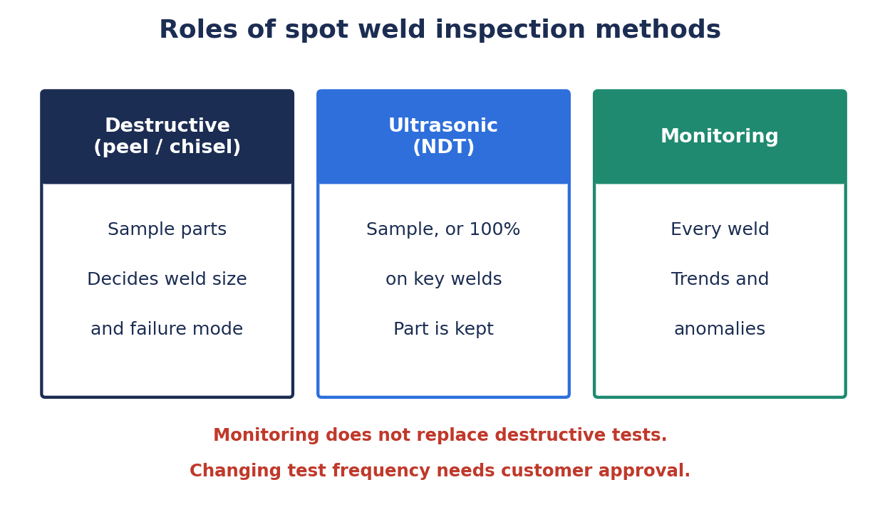
Destructive testing (peel, chisel): ISO 10447:2022 specifies procedures for determining weld size and failure mode through peel and chisel tests, and also includes verification by non-destructive chisel testing. Only destructive testing lets you directly see nugget size and how the weld fails, which makes it the reference for setting conditions and for routine checks.
On the other hand, destructive testing has weaknesses. A US Department of Energy report for fiscal year 2006 (Lawrence Berkeley National Laboratory) lists its drawbacks as scrap cost, ergonomic injuries to workers, the time lag between a problem occurring and its detection, and the absence of trend data, and states that because aluminum is expensive and hard to rework, teardown testing does not pay off. The same report set a goal of developing phased array ultrasonic inspection taking less than 4 seconds per weld. As this is an old document from fiscal year 2006, read it as background on the challenges, not as the current state of the technology.
Non-destructive testing (ultrasonic): A study published in the journal Materials in 2022 made 75 joints (5 per current level) from a combination of 0.8 mm electrogalvanized steel sheet and 1.2 mm hot-dip galvanized steel sheet and examined the relationship between ultrasonic reflected echoes and mechanical properties. It reports correlations of 0.41 between the number of reflected echoes and failure force and 0.50 with nugget diameter, and −0.69 between intermediate echoes and failure force and −0.72 with nugget diameter, and that a machine learning method achieved 95% accuracy. This is a laboratory study, and the same accuracy will not necessarily be achieved on a production line.
As a product example, for Waygate Technologies’ Krautkrämer SpotVision, according to the manufacturer’s announcement (September 2022), it is a portable phased array ultrasonic device for spot welds that uses a 13 MHz 2D matrix probe (32 elements) and TFM (Total Focusing Method).
Monitoring: Its role is to record the conditions of every weld and pick up trends and anomalies. It does not measure nugget diameter directly. Audi’s announcement (2023) explains that, whereas it previously performed sample-based analysis by ultrasonic testing, it is switching to a method in which AI analyzes data from all welds and focuses on anomalies. It states that it is working with the German Association for Quality (DGQ) and Fraunhofer to develop a form that can withstand audits and certification.
To repeat the key point: introducing monitoring does not eliminate destructive testing. If you are considering reducing the frequency of destructive tests, the prerequisite is to compare monitoring records with destructive test results over a set period, present that evidence, and obtain customer approval. You cannot lower the frequency without approval.
Responding to Abnormalities: Stop, Quarantine, Repair
If you do not decide in advance what to do when monitoring detects an abnormality, you end up in a state where the alarm sounds but nobody acts. For each type of abnormality, such as NG judgments, expulsion detection and current deviations, define the following 3 stages.
- Stop: Distinguish cases, for example stopping the line for an NG on a key weld while only issuing a warning for others and reviewing them at the next check. If everything triggers a stop, false alarms keep halting the line and the alarms end up being switched off
- Quarantine: If weld data is linked to part IDs, the quarantine range can be narrowed to “the part with the abnormal weld and a few parts before and after it.” Without that link, everything that ran since the last destructive test becomes subject to quarantine
- Repair: When repair welding (re-welding) is done, record which weld on which part was repaired, by whom and under what conditions. Also decide in advance how to verify the part after repair
Some controllers claim to automate even the repair. According to the manufacturer’s product page, the “SQA (Steel Quality Assurance)” function of ARO’s MFDC controller assigns each weld a quality rating as a percentage and automatically re-welds welds that fall below a threshold. Even when using automatic re-welding, it is essential to keep the fact of re-welding in the part’s record.
A system for recording the flow from quarantine through repair to re-inspection is explained in detail in our article on rework control systems. Managing weld repairs in the same register as rework in other processes lets you give the customer a single, consistent account.
When Materials Change: High-Strength Steel, Hot-Stamped Steel, Coated Steel and Aluminum
New EV parts bring more advanced high-strength steel (AHSS), hot-stamped steel, coated steel sheet and aluminum. When materials change, both welding conditions and monitoring thresholds have to be set again.
Here are research examples, presented with their scope.
- A study by Kershaw and colleagues at the University of Kentucky and GM (Journal of Manufacturing Processes, 2024) examined the hot-stamped steel Usibor 1500 with AlSi coating (40 μm), recording dynamic resistance, electrode force and displacement to study their relationship with expulsion. It covered a total of 627 welds on sheet thicknesses of 1, 1.4 and 1.8 mm, made by manual welding in a laboratory. The authors point out that while many existing physical models only address uncoated materials in controlled laboratory environments, coated steel sheet is the norm in actual production.
- A study by Fraunhofer IPK (published on AHSS Insights) predicts expulsion with AI by adding the nugget growth rate obtained through simulation to dynamic resistance and electrode force. It reports about 96% accuracy combining static data, dynamic measured data and simulation, and about 90% accuracy using only data from the first 30 milliseconds after the start of welding. The scope is a laboratory, with data from 500 welds on 2-sheet stacks of 1 AHSS grade and 1 mild steel grade (steel grades and thicknesses not disclosed). The study states that higher current greatly speeds up nugget growth and makes expulsion more likely.
As a product example for aluminum, Fronius introduced DeltaSpot in a 2018 article in its company magazine. According to the manufacturer’s announcement, a process tape runs between the electrode and the workpiece, up to 7,000 spots can be welded without interruption with 1 process tape, and electrode life is up to 20,000 welds depending on the application.
For AHSS welding conditions, the AHSS Insights guidelines mentioned earlier refer to AWS C1.1. When launching new parts, a practical sequence for setting conditions and thresholds is as follows.
- Confirm the minimum nugget diameter and failure mode requirements from customer specifications and standards
- Vary the current range on test coupons, measure nugget diameter by destructive testing, and set the target conditions
- Run production trials at the target conditions and capture the distribution of monitoring values (current, time, resistance, etc.)
- Compare the distribution with destructive test results and provisionally set warning and NG thresholds
- Keep destructive testing frequency on the high side during early production and review the thresholds
Rather than fixing thresholds from the start, planning to adjust them with launch-period data helps reduce both false alarms and missed detections.
Requirements to Write into the RFP
When you ask vendors to quote a monitoring system, vague requirements lead to proposals with inconsistent scopes that cannot be compared. Here are the items to write into the RFP (request for proposal).
| Item | What to write | What to confirm in vendor responses |
|---|---|---|
| Target equipment | List of guns and controllers (model, firmware, communication ports, quantity) | Classification per model: “available as is / available via configuration / additional hardware needed” |
| Data items and frequency | Required items from the table in Section 5; per weld only or including waveforms | Data volume and storage method if waveforms are captured |
| Part ID linking | Timing of ID reading, part-presence signals, whether lot-based operation is used | Handling of linking failures (display of missing records, re-linking) |
| Judgment logic and thresholds | Where thresholds are held (controller side or upper system), how SPC is used | Procedure and approval flow for changing thresholds |
| Retention period and backup | Retention years per part number, backup frequency and storage location | Capacity estimate and expansion method |
| Screens and reports | Per-weld lists, search by part ID, reports for submission to customers | Whether report formats can be changed |
| Alarm notification | Recipients, means, escalation | How to configure settings that reduce false alarms |
| Time synchronization | Synchronization method and allowable offset | How offsets are monitored |
| User permissions and change history | Who can change conditions and thresholds, retention of change history | Whether change history can be produced for audits |
| Integration with existing systems | Connection with MES, historian and quality systems | Connection method and division of responsibility |
| Calibration | Calibration of current sensors, monitors and checkers (the ISO 17657-4 approach) | Proposed calibration procedure and interval |
| Training and maintenance | Training for shop floor, maintenance and QA staff; maintenance structure (including Thai-language support) | Response time and contact point in case of failure |
How thresholds are held is a point that often sparks debate. According to the manufacturer’s product page, AMADA WELD TECH’s MG-300A can generate limits from SPC calculations. Even with a function that builds thresholds statistically, you still need to decide in-house who approves the final thresholds and how change history is kept.
FAT/SAT and Acceptance Criteria
When accepting equipment and software, verify in 2 stages: the factory acceptance test (FAT) before shipment and the site acceptance test (SAT) on site.
What to verify at FAT (before shipment)
- With simulated signals input, there are no gaps in the weld data records
- The judgment logic outputs OK and NG as specified (including values just above and below the boundaries)
- Linking of part IDs and welds works correctly with a simulated flow of parts
- No data gaps or duplicates occur when communication is lost and restored
What to verify at SAT (on site)
- Run the actual line for a set period and confirm the recording rate for all welds
- Confirm the linking rate to part IDs (the number of welds that could not be linked, and the causes)
- Time offsets between the controller, ID reader and server
- Alarms reach the designated recipients within the designated time
- Compare existing destructive test results with the monitoring records for the same parts
There are no industry-defined figures for the pass level of recording rate or linking rate. You decide them yourself. One approach is to set separate targets for key welds and other welds, for example “zero gaps in key weld records during the test period, and at least an in-house target value for other welds.” It is important to write the target values into the RFP before contracting, rather than deciding them after the fact at the acceptance stage.
Cost and Benefit Model Calculation (Illustrative Figures)
All figures from here on are illustrative figures prepared for this article. Because official prices for monitoring equipment could not be confirmed, costs are also placeholder assumptions. Please use this as a framework for your own calculations.
Assumed plant: A Japanese-affiliated automotive body parts plant in Thailand. 40 spot welding guns (30 robot guns, 10 stationary and manual guns), 4 lines, 2 shifts, 250 operating days per year. The hourly labor rate is assumed to be 300 THB.
Current costs (baseline, annual)
| Cost bucket | Baseline (per year) |
|---|---|
| Weld-related internal rework and scrap | 2,400,000 THB |
| Weld-related customer claim handling (sorting, transport, replacement) | 1,500,000 THB |
| Electrode tips and caps | 1,200,000 THB |
| Preparing and compiling paper and Excel weld check sheets | 60 hours/month |
| Destructive testing (chisel, peel) | 4,200,000 THB |
Destructive testing is 4 lines × 2 shifts × 250 days × 1 part = 2,000 parts per year. Parts cost 1,500 THB each, so 2,000×1,500 = 3,000,000 THB; labor is 2 hours per part × 300 THB = 600 THB, so 2,000×600 = 1,200,000 THB; the total is 4,200,000 THB.
Plan A: Data Collection from Existing Controllers + Part ID Linking + Tip Dressing Records + Dashboard
We assume an initial cost of 2,000,000 THB and an annual cost of 300,000 THB.
| Benefit | Calculation | Annual benefit |
|---|---|---|
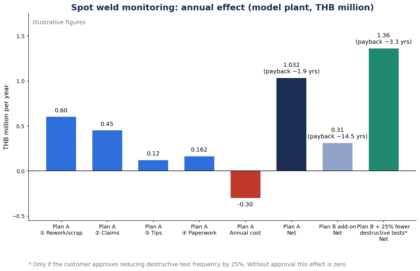
| (1) 25% reduction in internal rework and scrap | 2,400,000×25% | 600,000 THB |
| (2) 30% reduction in claim handling (weld data narrows the quarantine range) | 1,500,000×30% | 450,000 THB |
| (3) 10% reduction in tip costs (dressing and replacement records reduce premature replacement) | 1,200,000×10% | 120,000 THB |
| (4) Manual check sheet work cut from 60 to 15 hours per month | 45 hours×12 months×300 THB | 162,000 THB |
| Total benefit | 600,000+450,000+120,000+162,000 | 1,332,000 THB |
Net benefit is 1,332,000−300,000 = 1,032,000 THB/year, and the payback period is 2,000,000÷1,032,000 ≈ 1.9 years. Plan A does not count any reduction in destructive testing.
Plan B: Plan A Plus External Monitors / Adaptive Control on 10 Guns for Key Welds
This is evaluated as the increment after Plan A is in place. We assume an additional initial cost of 4,500,000 THB and an additional annual cost of 200,000 THB.
- Internal rework and scrap reduced by an additional 15% of the 2,400,000 THB baseline: 360,000 THB. This is not 15% of the 1,800,000 THB remaining after Plan A
- Claim handling reduced by an additional 10% of the 1,500,000 THB baseline: 150,000 THB
- Total additional benefit: 360,000+150,000 = 510,000 THB/year
The net benefit of the increment is 510,000−200,000 = 310,000 THB/year, and the payback period is 4,500,000÷310,000 ≈ 14.5 years. Under these conditions, the additional investment in Plan B should be regarded as not paying back.
Sensitivity analysis (only if the customer approves a 25% reduction in destructive testing frequency): Adding destructive testing cost of 4,200,000×25% = 1,050,000 THB to the additional benefit gives an additional benefit of 510,000+1,050,000 = 1,560,000 THB, a net benefit of 1,560,000−200,000 = 1,360,000 THB/year, and a payback period of 4,500,000÷1,360,000 ≈ 3.3 years. Without customer approval, this 1,050,000 THB benefit is zero.
Assumptions to Avoid Double Counting
- (a) (1) internal rework and scrap and (2) customer claim handling are kept as separate cost buckets
- (b) Plan B’s increment is set as a percentage of the baseline, not of what remains after Plan A. Combining Plans A and B, internal rework falls by 40% (25%+15%) and claim handling by 40% (30%+10%)
- (c) The reduction in destructive testing is included only in Plan B’s sensitivity analysis. It is included neither in Plan A nor in the base case
- (d) The tip cost reduction (3) is counted only in Plan A, not in Plan B
What the Calculation Shows
Most of the benefit comes from collecting data from existing controllers and linking it to parts (Plan A). External monitors and adaptive control should be limited to key welds and considered when there is a realistic prospect of agreeing with the customer on a review of destructive testing frequency.
Note that lost opportunity from line stoppages, winning new EV orders, reduced audit effort for standards compliance, and the effect of AI-based prediction are not included in this calculation.
Frequently Asked Questions
Where should resistance welding quality control start?
Start by deciding the key welds. From drawings and customer specifications, select the welds that affect strength or function, and make the first goal reliably keeping current, weld time, judgment result and part ID for those welds. If you try to manage all welds with equal weight, the shop floor cannot keep up with the data volume and the number of alarms.
Can weld current monitoring alone guarantee quality?
No. Weld current monitoring is evidence of whether conditions were on target, but current values alone cannot reveal when the nugget becomes small because of factors such as poor fit-up, tip wear or shunting. Explain quality by combining current records with tip dressing records, monitoring of voltage and electrode force where needed, and destructive testing.
How far does spot weld traceability need to go?
It depends on customer requirements and how far you want to narrow the quarantine range when an abnormality occurs. Linking welds to each part by serial number is the finest level, and linking by lot or fixture cycle number is the step before that. Retention years are also decided by customer requirements and internal rules.
What should electrode tip dressing management record?
The basics are the date and time of dressing, gun number, welds after dressing, date and time of tip replacement and cumulative weld count, and the number of stepper steps. There is no general right answer for the dressing interval, so decide it by testing with your own materials and conditions, and keep the basis for that decision as well.
What spot weld inspection methods are there?
There are 3: destructive testing (peel, chisel), non-destructive testing (mainly ultrasonic) and monitoring. Destructive testing is the reference that directly confirms nugget size and failure mode, ultrasonic testing is a means of checking samples or key welds without breaking parts, and monitoring is a means of picking up trends and anomalies across all welds. Their roles differ, so use them in combination.
Can data be collected even from old welding controllers?
It depends on the model. First, list the model, firmware and communication ports, and confirm with the manufacturer which items can be obtained. Even if data cannot be obtained via communication, you can compensate by measuring secondary current with an external monitor or by picking up only the judgment result via the PLC. Controller upgrades come after that, and should be considered only for key welds.
Can AI judge whether spot welds are good or bad?
Results have been reported in research, but their scope is limited. Fraunhofer IPK’s expulsion prediction is a result from 500 welds in a laboratory on combinations of 2 types of steel sheet. A 2018 study by Zhou and colleagues at Bosch and KIT predicts nugget diameter by generating labeled data through finite element simulation; it covers a simplified simulation of 1 welding machine and 3 programs, and the authors themselves explicitly state that the results cannot be generalized. The same study also recommends starting with 250 labeled data points and points out that performance drops significantly with measurement uncertainty. To use AI on a production line, a stage of building up your own destructive test results as ground-truth data and verifying accuracy in-house is indispensable.
Summary
- Before it is about adding equipment, spot welding monitoring is about deciding “which welds’ data you keep, against which part numbers, and for how many years”
- The first 3 steps: decide key welds, collect data from existing controllers and link it to part IDs, and record tip dressing and electrode life
- Weld data can only be used to explain things to customers once “part ID,” “weld ID” and “timestamp” are all in place. Firm up linking with time synchronization and part-presence signals
- Read product features as manufacturers’ announcements and verify them on your own line. Communication methods differ greatly by model and generation, so start by making a list
- Get the overall picture of standards from their numbers and titles, and check the details in the original texts and customer specifications. Welding current meters and monitors are subject to calibration
- Destructive testing does not go away with monitoring. To change its frequency, obtain customer approval based on comparison with the records
- In the illustrative calculation, most of the benefit came from Plan A (data collection and linking). Consider external monitors and adaptive control only for key welds
For how to handle welding data within production management as a whole, see also our article on production management systems for automotive parts plants.
TOMAS TECH can help even at an early stage, such as taking stock of which welds should be key welds and which data can be obtained from your existing controllers, or organizing RFP requirements. Please contact us through this form.
References
- https://www.sis.se/en/produkter/manufacturing-engineering/welding-brazing-and-soldering/welding-processes/iso-143732024/
- https://www.evs.ee/en/evs-en-iso-10447-2022
- https://knowledge.bsigroup.com/products/resistance-welding-weldability-evaluation-procedures-for-weldability-in-spot-welding
- https://www.boutique.afnor.org/en-gb/standard/iso-1767712021/resistance-welding-vocabulary-part-1-spot-projection-and-seam-welding/xs138930/241179
- https://www.boutique.afnor.org/en-gb/standard/iso-1765742005/resistance-welding-welding-current-measurement-for-resistance-welding-part-/xs015482/111797
- https://pubs.aws.org/p/2067/d81m2021-specification-for-automotive-weld-quality-resistance-spot-welding-of-steel
- https://din.de/de/wdc-beuth:din21:281800771
- https://blog.aiag.org/new-publication-alert-version-2-of-the-cqi-15-special-process-welding-system-assessment-is-now-available-at-the-aiag-store
- https://www.boschrexroth.com/en/us/company/press/adaptive-resistance-welding-controller-1984.html
- https://boschrexroth.com/en/au/blog/welding-a-gateway-to-industry-4-0
- https://www.boschrexroth.com/en/at/company/press/welding-control-prc7000-20160.html
- https://www.amadaweldtech.eu/products/resistance-welding/weld-checkers/mm-410a-portable-weld-checker
- https://www.amadaweldtech.eu/print/products/resistance-welding/advanced-process-monitoring/wm-r100a-advanced-data-analysis-monitor
- https://www.amadaweldtech.eu/products/resistance-welding/advanced-process-monitoring/mg-300a-digital-weld-monitor-resistance-spot
- https://weldtechcorp.com/products/View-Net.html
- https://tjsnow.com/resistance-welding-supplies/controls/harms-wende/genius-inverter/
- https://www.arotechnologies.com/?p=1171
- https://www.fronius.com/en-us/usa/welding-technology/info-centre/magazine/2018/getting-straight-to-the-point
- https://www.bakerhughes.com/waygate-technologies/news/waygate-technologies-launches-new-ultrasonic-inspection-solution-0
- https://www.marklines.com/en/news/351560
- https://www.nst.com.my/amp/business/economy/2026/08/1518403/thailand-car-production-rises-61pct-year-july
- https://www.mreport.co.th/en/tag/news/%E0%B8%81%E0%B8%A5%E0%B8%B8%E0%B9%88%E0%B8%A1%E0%B8%A2%E0%B8%B2%E0%B8%99%E0%B8%A2%E0%B8%99%E0%B8%95%E0%B9%8C%20%E0%B8%AA.%E0%B8%AD.%E0%B8%97.
- https://www.mreport.co.th/en/news/statistic-and-ranking/552-thailand-automotive-production-june-2026
- https://www.argusmedia.com/news-and-insights/latest-market-news/2781852-thailand-ev-boom-drives-auto-market-in-2025
- https://www.krungsri.com/en/research/industry/industry-outlook/hi-tech-industries/automobiles/io/automobile-2026
- https://osos.boi.go.th/article_attach/PR167_2567EN.pdf
- https://osos.boi.go.th/EN/news/2302/
- https://www.nationthailand.com/business/automobile/40071986
- https://www.twi-global.com/locations/south-east-asia/news-and-events/news/2026/twi-thailand-partners-with-department-of-skill-development
- https://researchportalplus.anu.edu.au/en/publications/process-monitoring-of-resistance-spot-welding-using-the-dynamic-r/
- https://ahssinsights.org/?p=661923
- https://ahssinsights.org/?p=1073
- https://publikationen.bibliothek.kit.edu/1000105460/56698070
- https://par.nsf.gov/servlets/purl/10499757
- https://www.jstage.jst.go.jp/article/qjjws/27/3/27_3_230/_article
- https://uwaterloo.ca/centre-advanced-materials-joining/sites/default/files/uploads/files/sct-20062_chen.pdf
- https://pmc.ncbi.nlm.nih.gov/articles/PMC8911221/
- https://www1.eere.energy.gov/vehiclesandfuels/pdfs/alm_06/6a_hopkins.pdf
- https://www.audi.com/en/press-releases/audi-begins-roll-out-of-artificial-intelligence-for-quality-control-of-spot-welds-15443


