


A successful industrial robot implementation in a Thailand factory depends less on selecting an impressive arm than on executing the work after application selection. User requirements (URS), integration boundaries, risk assessment, safety functions, FAT/SAT, handover and operational change control must form one traceable evidence chain. This guide starts from the 2025 edition of ISO 10218 and explains the owner’s work from concept freeze to sustained production.
It is not another list of robot types or system integrators. It is for plants that already have a candidate process and now need to define responsibilities and acceptance. Safety circuits, required performance levels, stopping distance, collaborative-operation feasibility and legal conformity require review by competent machinery-safety, mechanical and control specialists using the actual site conditions. No article alone can establish conformity.
Read the implementation boundary from ISO 10218:2025
ISO’s public information explains that ISO 10218-1:2025 addresses safety requirements for an industrial robot as partly completed machinery. ISO 10218-2:2025 addresses integration of industrial robot applications and cells, including design, integration, commissioning, operation, maintenance and decommissioning. The second boundary is where the end-effector, workpiece, fixtures, conveyors, safeguards, control system and human tasks combine.
Buying a robot with safety capabilities is therefore not the same as accepting a safe production cell. Crushing, ejection, dropped workpieces, heat, welding, cutting, laser, dust, electricity, pneumatics and hazardous materials can arise from the application. They must be assessed at the integrated-system boundary.
| Scope | Main responsibility focus | Evidence to request |
|---|---|---|
| Robot | Intended use, limits, embedded safety functions and information for use | Applicable standards, declarations, manuals, limits and safety I/O |
| End-effector | Gripping, tooling, stored energy and workpiece retention | Load cases, loss-of-hold behavior, maintenance isolation and tests |
| Application | Combination of robot, tool, workpiece and process hazards | URS, risk assessment, reduction measures and validation plan |
| Cell | Safeguards, transfer, fixtures, controls, surrounding machines and access | Boundary drawing, safety requirements, FAT/SAT and residual risks |
| User operation | Training, inspection, release, change, contractors and disposal | SOPs, LOTO, competence records, change control and periodic validation |
State the edition explicitly in an RFP—such as ISO 10218-1:2025 and ISO 10218-2:2025—and separately identify local law, customer rules, legacy-equipment constraints and validation responsibility. Obtain the official standards and have competent specialists translate applicable clauses into project requirements.
Define production that must work in the URS
The first deliverable after application selection is a User Requirements Specification, not a manufacturer model sheet. “20 kg payload and 1,800 mm reach” describes a component; the URS states what products must be made, under what conditions, at what quality and capacity, and how the cell must stop, recover and be maintained.
Nine requirement groups for an implementable URS
| Group | Contents | Acceptance question |
|---|---|---|
| Product/process | Variants, mass, tolerances, surface, temperature, oil and burrs | Can the worst credible workpiece be reproduced? |
| Capacity | Cycle, operating hours, changeover and WIP limits | Is sustained good output demonstrated? |
| Quality | Position, torque, dispensing, weld, appearance and traceability | Are measurement method and decision owner agreed? |
| Environment | Heat, humidity, dust, water, chemicals, power and air | Are any conditions outside equipment ratings? |
| Human intervention | Refill, sampling, cleaning, tool change and jam release | Were frequency and body position observed? |
| Safety | Access, stops, restart, modes, emergencies and residual risk | Is every safety function verifiable? |
| Interfaces | PLC, MES, quality, andon, network and time | Are signal ownership and failure behavior defined? |
| Maintenance | Diagnostics, spares, backup, restoration and remote support | Can faults be diagnosed safely? |
| Handover | Drawings, source, credentials, training, warranty and acceptance | What objective evidence releases payment? |
Measure cycle performance as sustained good production, including feed, inspection, discharge, cleaning, changeover, minor stops and recovery. Test maximum and off-center loads, slippery or variable surfaces and tolerance extremes—not only a perfect demonstration part. Record assumptions and the safe response when they fail. For the earlier supplier-selection stage, see our Thailand robot system integrator guide.
Freeze integration boundaries in one drawing and responsibility matrix
The costliest omissions occur between the robot and PLC, new cell and legacy conveyor, integrator and machine supplier, OT and IT, or owner-furnished and contractor-furnished equipment. Freeze physical, functional, safety, information and commercial boundaries at kickoff.

| Boundary | Interface | Normal condition | Safe behavior on failure | Evidence owner |
|---|---|---|---|---|
| Robot–gripper | Flange, electrical, air and safety status | Retain and move workpiece | Prevent or contain drop/ejection | Calculations and loss-of-energy tests |
| Cell–conveyor | Position, I/O and interlocks | Authorized transfer | Do not start hazardous motion | Timing diagram and fault injection |
| Safeguard–building | Floor anchors, openings, overhead and escape | Prevent access | Permit rescue and evacuation | Survey, installation and SAT |
| Safety PLC–standard PLC | Safety communication and status | Modes agree | Standard-control failure cannot defeat safety | SRS and independent validation |
| OT–IT | VLAN, time, backup and remote service | Authorized traffic only | Network failure cannot create hazardous motion | Connectivity and account audit |
RACI is not enough. Assign who designs, verifies, approves, retains and revalidates each deliverable. Owner-supplied fixtures remain part of the integrated risk if they influence the cell. Version-control the I/O list, communication tags, state model, coordinate systems and layout under one baseline and link every change to its impact assessment and test result.
Use ISO 12100-style risk assessment as a design input
The public ISO 12100:2010 description provides general principles for machinery risk assessment and risk reduction. ISO shows the edition as confirmed in 2022 while a revision project is progressing. Check the current status at the decision date and do not present draft revision work as an existing requirement.
Risk assessment is not a signature collected after build. Iterate through machine limits, intended use and reasonably foreseeable misuse; identify hazards across the lifecycle; estimate and evaluate risk with an approved method; reduce risk through inherently safe design, engineering safeguards and information for use in that order; then identify any new and residual risks.
| Task | Person’s position | Typical hazard | Design direction |
|---|---|---|---|
| Automatic operation | Outside guard, near transfer opening | Reach-in, ejection and transfer intrusion | Distance, opening control, interlock and retention |
| Teaching | Inside or close to cell | Trapping, unexpected start and unseen axes | Mode selection, enabling device, speed and lone-work rules |
| Jam release | Near hazard point | Gravity, springs and trapped pressure | Isolation, dissipation, verification and tools |
| Tool change | Near flange or process tool | Drop, sharp edge and heat | Support, restraint, cooling and procedure |
| Cleaning/inspection | Frequent access point | Bypass and unplanned motion | External access and monitored stop |
| Diagnosis | Panel or cell interior | Live electrical and motion diagnosis | Controlled diagnostic mode, authority and audit |
A safety fence is one possible measure, not a conformity verdict. Distance to hazards, reach direction, openings, under-clearance, climbing, transfer apertures, stopping performance, workpiece ejection, maximum and restricted spaces, and maintenance access must be evaluated together. A search for “robot safety fence standard” should lead to a task-specific assessment and specialist measurement, not a catalog dimension.
Treat the end-effector and retained workpiece as safety-critical
ISO/TR 20218-1:2018 provides safety-design guidance for industrial robot-system end-effectors. A vacuum tool requires evidence for material and surface variation, cup wear, leakage, source loss, monitoring and retained energy. Mechanical gripping must consider friction variation, center of gravity, acceleration, jaw wear and wrong-part loading. Welding, spindle and laser tools add heat, fume, radiation, cooling and fragment hazards.
Acceptance must cover power or air loss, sensor failure, worst-case workpieces, simulated wear, emergency and protective stops, and restart. “The robot stops” does not prove that the workpiece remains controlled. Validate stopping and retention as separate requirements.
Define safety functions in an SRS, not by device name
A Safety Requirements Specification defines trigger, hazard, affected actuators, demanded safe state, response, reset, restart prevention, fault behavior, diagnostics and validation for each safety function.
| ID | Trigger | Required state | Reset/restart | Validation evidence |
|---|---|---|---|---|
| SF-01 | Guard door opens | Hazardous motion reaches safe state within validated performance | Door closed plus manual reset; reset cannot start | Wiring, stop measurement and fault injection |
| SF-02 | Emergency stop | Defined emergency response across affected hazards | Release alone cannot restart | Every device, mode and restoration path |
| SF-03 | Presence detected | Inhibit start or execute monitored stop | Confirm hazard area clear | Scenarios including muting |
| SF-04 | Grip fault | Restrict motion and retain or safely reject part | Controlled recovery after cause check | Pressure loss, sensor and power tests |
| SF-05 | Mode selection | Only permitted equipment, speed and behavior available | Key/authority and clear indication | Mode transitions and speed measurement |
ISO 13849-1:2023 publicly describes a methodology for designing and integrating safety-related parts of control systems, including software. It does not prescribe the safety function or required performance level (PLr) for a particular application. Derive PLr from risk assessment per function, then have competent specialists evaluate architecture, component reliability, diagnostics, common-cause failure, software and validation.
A safety PLC alone is not the result. Trace the chain from input through logic, communications and output to drives, valves, contactors and mechanical stopping. Keep standard-control status separate from safety signals and assign validation with appropriate independence.
Collaborative robots follow the same sequence. A collaborative-capable arm does not automatically remove the need for safeguarding. Tooling, workpiece, speed, contact location, peripherals and non-collaborative modes remain part of the application. See the Thailand collaborative robot implementation guide and translate its findings into this project’s SRS.
Compare industrial robot price through TCO and a real RFQ
There is no responsible fixed answer to “industrial robot price.” The same arm can produce very different project totals after tooling, vision, safety, legacy modification, installation, testing, training and support. Compare real quotations against the same URS instead of inventing a market range.
| Cost group | Initial items | Lifecycle items |
|---|---|---|
| Robot/control | Arm, controller, pendant and safety options | Service, spares and obsolescence |
| Application | Gripper, fixtures, vision and process package | Consumables, calibration and retuning |
| Cell integration | Base, guards, sensors, safety PLC and panels | Inspection and periodic revalidation |
| Existing plant | Conveyor, utilities, floor, extraction and network | Shutdown work and capacity constraints |
| Engineering | Design, assessment, software and simulation | New variants and software changes |
| Deployment | Transport, installation, FAT/SAT and training | Ramp-up and off-hours support |
| Operation/end | Labor, energy, maintenance, licenses and disposal | Downtime, lock-in, migration and recovery |
Measure benefits from a common baseline: throughput, yield, rework, exposure to hazardous tasks, changeover, absentee resilience, traceability, energy, WIP and downtime. Use optimistic, base and conservative scenarios with demand, learning curve, maintenance shutdowns and product life. Safety controls are not optional items to remove when a simple payback is weak.
Thailand BOI material must also be read narrowly. The published 2026–2027 measure referenced here is for the automotive industry. Its minimum investment is THB 1 million, excluding land and working capital. The corporate-income-tax exemption lasts three years and is capped at 50% of qualifying automation-and-robotics investment; the cap rises to 100% when machinery linked to or supporting Thailand’s domestic automation-machinery industry represents at least 30% of the relevant machinery value. The application window runs from the first working day of 2026 through the last working day of 2027. The 50% and 100% figures are exemption caps, not tax rates or cash-grant rates. These are conditional incentives, not a universal subsidy for every factory. Confirm the entity, eligible activity, project timing, domestic-linkage calculation and eligible expenditure with BOI or a qualified adviser before commitment.
Make vendor RFQs comparable
Issue the same URS, boundary matrix, site survey, layout assumptions, applicable-standard list, acceptance outline and commercial conditions. Require compliance, partial compliance, deviation and clarification against every requirement ID. Compare responsibility for machinery, electrical, control, safety, IT/OT and production; competence for risk assessment and validation; demonstrated cycle assumptions; source code and credential transfer; Thai-language training; support and spares; and change rates tied to accepted deliverables.
For staged projects, our small-manufacturer automation cases in Thailand show why a bounded first cell can establish reusable standards without pretending that every process should be fully automated.
Turn FAT into requirements and risk validation
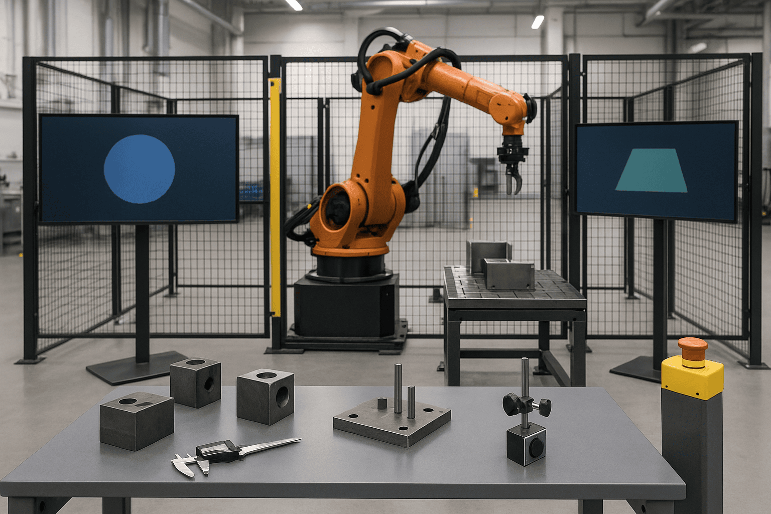
FAT is not a demonstration of a few successful cycles. It closes URS requirements, interfaces, risk-reduction measures, safety functions, recovery and documentation with traceable records, using representative workpieces, upstream/downstream simulation and an approved software baseline.
| Test group | Normal cases | Fault/boundary cases | Record |
|---|---|---|---|
| Capacity | Sustained production, variants and quality | Worst parts, late feed and minor stops | Time, count, defects and stop reason |
| Safety | Modes, closed guards and normal stop | Door, E-stop, sensor fault and restart | Function ID, response, instrument and result |
| Retention | Pick, transfer and release | Power/air loss, wrong part and wear | Workpiece condition and recovery |
| Interfaces | Handshake and history | Timeout, stuck signal, link loss and reconnect | I/O revision, logs and state transition |
| Recovery | Planned stop/start | Power loss, PLC restart, robot fault and jam | Procedure, authority and recovery time |
| Documentation | Drawings, BOM and manuals | Revision mismatch and restore test | Register, revision, approval and restoration |
Record response and stopping performance, affected actuators, reset location, prevention of unintended restart, diagnostic coverage and bypass control—not merely “stopped.” Retain instrument/calibration status, software version, tester, date, deviation, correction and retest. A punch list needs severity, owner, deadline, SAT impact and payment retention. Safety, legal, critical-quality and unrecoverable items require an explicit shipment gate.
Use SAT to validate the real Thailand factory
SAT validates the transported and installed cell against actual floor, anchors, power, air, network, heat, dust, lighting, transfer systems, operators, shifts and maintenance organization. Recheck datum, coordinates, fasteners, wiring, protective bonding, leakage, safeguards, time synchronization and backups after installation.
Capability tests should include breaks, replenishment, sampling, changeover, handover and minor stoppages. Plant personnel must demonstrate start, normal stop, jam recovery, recipe change, routine inspection and backup restoration without the integrator doing the work.
| Requirement | Purpose | FAT | SAT | Approval |
|---|---|---|---|---|
| URS-CAP-01 | Sustained good output | Simulated-line run | Real-line capability | Production owner |
| SRS-SF-01 | Safe response to door opening | Fault injection and stop measurement | Repeat after installation | Safety owner |
| URS-REC-02 | Recovery after power loss | Simulated outage | Site power test | Maintenance owner |
Reopen affected rows whenever a change occurs. This traceability prevents requirements from disappearing and test results from losing their purpose.
Complete handover of documents, competence and ownership
Production start is only part of handover. Deliver approved as-built mechanical, electrical, pneumatic, I/O, network and configuration records; risk assessment, SRS, validation and residual-risk files; buildable sources, licenses and backups; credential and remote-access transfer; operating, cleaning, jam-release, LOTO, diagnostic and restore procedures; role-based Thai-language training with practical assessment; spares, warranty and obsolescence plans; and a controlled punch list.
Attendance is not competence. Operators should demonstrate safe start, stop and recovery; maintainers should demonstrate isolation, diagnosis and restoration; administrators should demonstrate access control, change authorization and evidence preservation.
Protect safety and ROI through change control
Products, tools, trajectories, speeds, PLC software, networks and work methods will change after launch. Treat each modification as technical, safety and operational reauthorization: record before/after state; screen mechanical, electrical, control, safety, quality, IT/OT and training impacts; update the URS, risk assessment, SRS, drawings and procedures; implement under version control; run proportionate regression and safety-function tests; retrain; approve release; and review side effects.
Emergency night-shift edits, remote vendor changes, taught-point adjustments and temporary bypasses are not exceptions. Give emergency changes an owner, expiry, interim risk reduction and next-business-day review. Track production together with safeguards bypassed, protective stops, jams, manual interventions, MTTR, repeat faults, quality loss and post-change defects.
A 90-day execution example
The durations are planning examples, not industry benchmarks.
| Period | Work | Gate |
|---|---|---|
| Days 1–15 | Observation, baseline, URS, boundary and initial risk | Approved RFQ package |
| Days 16–30 | Proposal comparison, concept and TCO | Technical/commercial selection |
| Days 31–55 | Detailed design, SRS and risk reduction | Design baseline and validation plan |
| Days 56–70 | Build, software, internal test and training preparation | FAT-ready package |
| Days 71–78 | FAT, correction and shipment decision | FAT evidence and punch list |
| Days 79–88 | Installation, SAT, safety, capability and recovery | SAT and competence evidence |
| Day 89 onward | Stabilization, final handover and KPI review | Final baseline and improvement list |
The important feature is the gate, not the speed. A risk assessment postponed until FAT leaves little room to change access, guards, drives or safety I/O.
FAQ about industrial robot implementation
How much does an industrial robot cost?
The arm price is not a project price. Obtain actual RFQs against one URS and compare tooling, safety, plant modification, engineering, FAT/SAT, training, support, downtime and end-of-life TCO. An unsupported online range is less useful than quotations normalized to the real site.
Where should a robot-arm implementation start?
Observe the process and write a URS covering product, capacity, quality, intervention and recovery. Then establish the integration boundary, task-based risk assessment, SRS and acceptance tests before freezing the model.
How should robot implementation ROI be measured?
Measure current throughput, yield, labor time, downtime, rework, absence, energy and WIP, then use the same definitions after launch. Include maintenance, consumables, licenses, modifications, downtime and disposal in TCO, with multiple demand scenarios.
Which standard determines a robot safety fence?
ISO 10218-2:2025 is among the relevant standards, but a fence dimension alone does not establish conformity. Evaluate hazards, reach, openings, stopping performance, ejection, transfer apertures and maintenance access. Have competent specialists apply the official standards and local requirements.
When should we request robot implementation support?
Before freezing the URS and responsibility boundary is ideal. An existing quotation can still be audited against requirement IDs, exclusions, SRS, FAT/SAT and handover. Specialist review remains necessary for safety design and conformity conclusions.
Does following ISO 10218:2025 mean the cell is certified?
No. Scope, edition, applicable law, design, installation, use conditions and validation evidence all matter. Robot information under Part 1 does not by itself establish conformity of the integrated application under Part 2.
Conclusion: close industrial robot implementation with evidence
Industrial robot implementation defines working production in the URS, freezes interfaces, converts task risk into safety functions, verifies them in FAT/SAT, transfers documents and competence, and maintains the baseline through change control. Understanding the Part 1/Part 2 boundary prevents a safe robot component from being mistaken for a safe integrated cell.
TOMAS TECH can help a Thailand factory structure an early URS, integration boundary, TCO and FAT/SAT package. We coordinate machinery, controls, IT/OT and operations while including competent specialist review for safety circuits, risk assessment and standards conformity. Contact us, even while requirements are still being shaped.
Primary references
- ISO, ISO 10218-1:2025
- ISO, ISO 10218-2:2025
- ISO, ISO 13849-1:2023
- ISO, ISO 12100:2010
- ISO, ISO/TR 20218-1:2018
- A3, ANSI/A3 R15.06-2025 notice
- IFR, World Robotics 2025
- Thailand BOI, Automation measures
*Facts checked 1 September 2026. Public standard descriptions are used; paid standards are not reproduced. Recheck standards, law and BOI conditions before a decision.*


