


The moment you start planning an equipment upgrade or an automation project on a factory floor, one acronym shows up in every conversation — PLC. It appears in machine builders’ quotations and in control panel specifications as if everyone already knows what it means, yet very few people have ever had it explained to them properly. This article is written for readers meeting the PLC for the first time. It walks through the definition, the basic hardware makeup, the operating principle, how to read a ladder diagram, and how the different product classes differ, unpacking the jargon one term at a time.
What a PLC Is — Defining the Industrial Controller That Runs Factory Machines
The full name, and why some people call it a “sequencer”
PLC stands for Programmable Logic Controller. In one sentence, it is a compact industrial computer that determines the operating sequence of a machine through a program you can rewrite at any time.
On the shop floor you will also hear the word “sequencer.” That is a nickname derived from the product name Mitsubishi Electric gave its PLC line, which became so widespread in Japan that it turned into a generic term. As a category of equipment, a sequencer and a PLC are exactly the same thing. In Japanese-affiliated plants in Thailand this creates a predictable mix-up — the Japanese staff say “sequencer” while the local engineers say “PLC,” and both sides briefly wonder whether they are discussing different hardware. They are not.
The Japan Electrical Manufacturers’ Association (JEMA) positions the PLC as having evolved beyond a simple sequence control device into a “key component for building systems,” now responsible for arithmetic control, information processing and networking as well. In other words, a PLC today is no longer just a box that makes machines move in order; it is also the junction where factory data comes together.
What a PLC actually does — read inputs, evaluate conditions, drive outputs
The job of a PLC can be summarised in three surprisingly simple lines.
- Read the state of sensors and switches out on the floor (input)
- Compare that state against predefined conditions and decide what should happen (logic)
- Send signals that drive motors, valves and lamps (output)
Take a sentence like “if the safety cover is closed, and the workpiece is in position, and the start button has been pressed, then run the conveyor.” A PLC is simply a device that executes that sentence literally. On the input side you connect limit switches, photoelectric sensors, proximity sensors, pushbuttons and temperature sensors; on the output side, magnetic contactors, solenoid valves, indicator lamps, inverters and servo amplifiers.
How a PLC differs from a PC or a microcontroller board
It is a fair question to ask why an industrial PC or an inexpensive microcontroller board would not do the same job. PLCs continue to be chosen for factory duty because they ship with the following properties built in from the start.
- A guaranteed operating cycle. Thanks to the scan method described later, processing time stays within a predictable window. There is no general-purpose operating system that can suddenly slow things down with background work.
- Tolerance of the electrical environment on the floor. 24 V DC I/O, noise immunity, isolation and a wide operating temperature range are standard.
- A design premised on never stopping. Many models have no hard disk and no fan, and are built to run continuously for years with the power left on.
- Something maintenance staff can work on. Because ladder diagrams are a shared notation, someone other than the original developer can follow the logic.
- I/O you can add later. Point counts expand simply by adding modules.
Put differently, a PLC is not “a computer that calculates fast” but “a computer that performs a fixed job within a fixed time, without stopping, for years.” That difference in design philosophy is why the PLC has survived as a product category for more than fifty years.
The Building Blocks of a PLC — CPU, I/O Modules, Power Supply and Programming Software
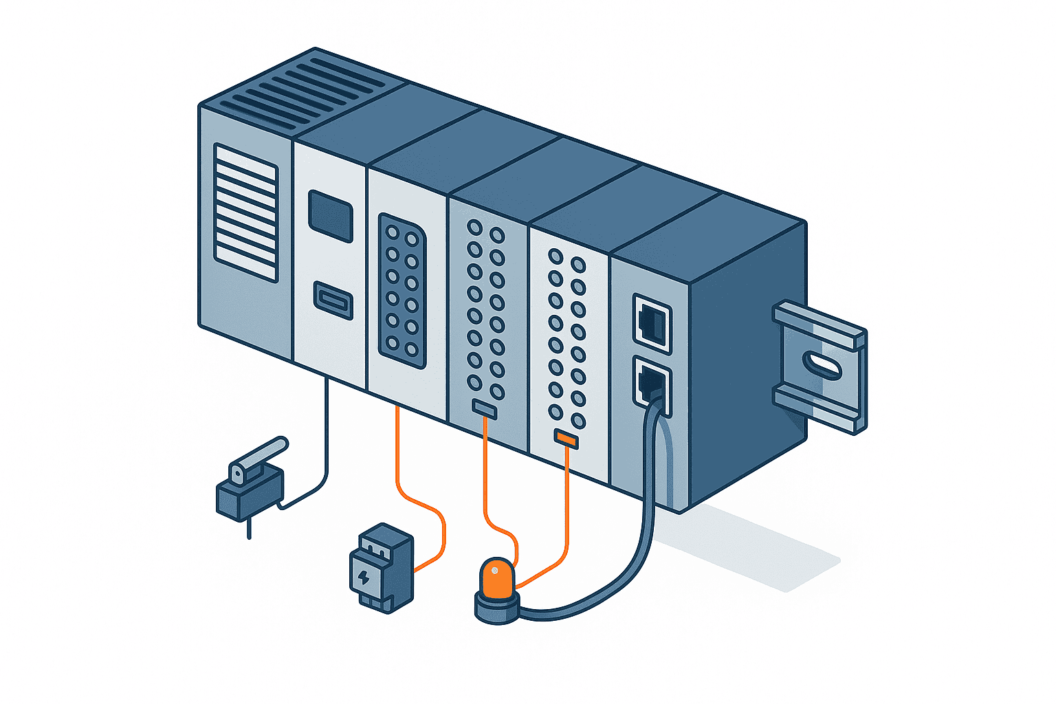
A PLC is an assembly of several units, or modules. Using Mitsubishi Electric’s MELSEC iQ-R series as an example, the documentation describes a system as being made up of a CPU module, a base unit, a power supply module, input and output modules, analog modules, temperature control modules, positioning and motion modules, high-speed counter modules and network modules. The naming varies a little between manufacturers, but the way the roles are divided is almost identical across the industry.
CPU module — the brain that executes the program
This is the unit that stores and runs the program. Reading input states, evaluating logic and deciding outputs all happen here. Memory capacity, expressed as the number of program steps it can hold, and processing speed are the headline specifications, and they are the central factors determining which class a model belongs to. A run/stop switch, error indicator LEDs and a memory card slot are typically located on the front face.
Input and output modules — the interface with the floor
Input modules convert signals from sensors and switches into data the PLC can handle. Output modules do the reverse, passing the PLC’s decisions to field devices as electrical signals.
Digital I/O — plain on/off signals — is the baseline, but there are purpose-built variants as well: analog modules that handle continuous voltage or current values, temperature input modules that accept thermocouples and RTDs directly, and high-speed counter modules that count fast pulse trains.
It is worth noting that because I/O modules are physically wired to the field, they are also the part most likely to fail. In JEMA’s “FY2024 PLC User Survey,” conducted from August to October 2024 with the report published in March 2025, machine builders identified “I/O” as the most common failure location at 52.0 percent, followed by “power supply” at 38.2 percent and “CPU” at 23.0 percent. That distribution is worth remembering when you are deciding at design time how many spare modules and how much surplus point capacity to hold.
Power supply and base units — the foundation of the system
The power supply module feeds the CPU and the I/O modules. The base unit is the backplane that the modules plug into and that connects them to one another over an internal bus. In compact PLCs, both are integrated into the CPU itself.
Programming software — how you teach a PLC its job
A PLC on its own does nothing. You create the program in engineering software on a PC and transfer it to the controller over USB or Ethernet. Mitsubishi Electric’s GX Works, Keyence’s KV STUDIO, Omron’s Sysmac Studio, Siemens’ TIA Portal and Rockwell’s Studio 5000 are the representative examples.
This point is easy to overlook, but the software is different for every manufacturer, and most of it is licensed commercial software. Buying a PLC does not mean you can start programming immediately. The software licence cost and access to an engineer who can use it come as a package with the hardware, so build both into the budget when you evaluate a project.
Network modules — connecting factory data
These units link PLCs to one another, or a PLC to a higher-level system. Looking at machine builder responses in the same JEMA survey, the networks adopted at controller level were “EtherNet/IP” at 54.3 percent and “CC-Link IE” at 41.9 percent, while at device level “CC-Link” stood out at 67.0 percent. Which communication standard you choose is decided by compatibility with existing equipment on one side and room for future expansion on the other.
Relay Control Versus PLC Control — Why the PLC Was Invented
Life before the PLC — the relay panel
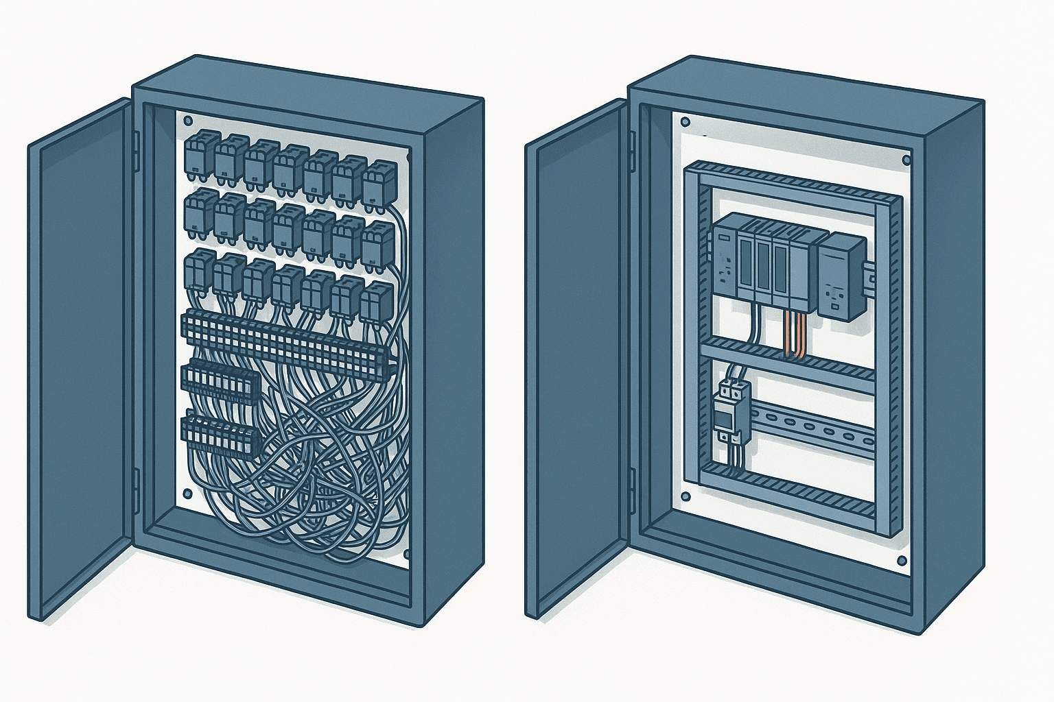
Before the PLC arrived, the operating sequence of a machine was implemented as a circuit of relays. A relay is a component whose contacts switch over when current flows through its coil, and by wiring dozens or hundreds of them together, engineers constructed logic such as “if A and B, then C.”
This approach had one decisive weakness: the only way to change the behaviour was to rewire the panel. Whenever the product being manufactured changed, someone had to open the cabinet, pull and re-land wires, redraw the drawings and verify the operation. It was not unusual for that to take several days. Relays themselves are consumable parts with mechanical contacts, so the more of them a panel contained, the higher the probability of failure — and tracking down which contact had gone bad was its own ordeal.
General Motors’ 1968 request and the Modicon 084
The turning point came in 1968. The Hydramatic Division of General Motors in the United States issued a request for proposals to replace its hard-wired relay systems with an electronic alternative. Behind it lay exactly the limitations of the relay approach described above — every change meant redoing wiring and drawings, and isolating faults was laborious.
The contract went to Bedford Associates, and because it was the company’s eighty-fourth project, the resulting device was named the “084.” It was completed and delivered in 1969, and is regarded as the world’s first PLC. Richard “Dick” Morley, who worked on its development, later came to be known as the father of the PLC. The company went on to found Modicon, a name derived from Modular Digital Controller. The Modicon brand is today owned by Schneider Electric.
This history carries two implications that matter for understanding the modern PLC. The first is that the PLC was created specifically to let you change machine behaviour without rewriting the wiring. The second is that a notation resembling relay ladder schematics was deliberately adopted so that the electricians already on the floor could work with it unchanged. That second point is the origin of the ladder diagram covered in the next section.
Relay control and PLC control side by side
Laying out the differences point by point gives the following picture.
| Aspect | Relay control | PLC control |
|---|---|---|
| Changing behaviour | Requires rewiring | Handled by editing the program |
| Panel size | Grows in proportion to the logic | Stays compact; add modules instead |
| Wiring volume | Wiring increases with every logic element | Only wiring to field devices |
| Fault isolation | Relies on visual checks and continuity testing | Internal states visible via monitor functions |
| Logic complexity | Becomes impractical as logic grows | Handles timers, arithmetic and communications |
| Initial cost | Cheap at small scale | Requires up-front hardware and software cost |
| Maintenance parts | Periodic replacement as contacts wear | Module replacement as components age |
What this comparison reveals is a structural crossover: relays are cheaper while the system stays small, and beyond a certain scale the PLC becomes overwhelmingly advantageous.
Why relays are still around
To avoid any misunderstanding, relays have not disappeared from factories. PLC output modules cannot switch large currents directly, so making and breaking a motor’s main circuit remains the job of a magnetic contactor. Equally important, safety functions such as emergency stop and safety-door interlocks should as a rule be built independently with safety relays or a safety PLC rather than mixed into the ordinary PLC program. The reason is to prevent a software defect from taking the safety function down with it, and the practice follows the thinking required by machinery safety standards such as ISO 13849-1 and IEC 62061. Even at the introductory stage, hold on to this one distinction: “the logic that makes things move” and “the safety circuit that makes them stop” are separate things.
How a PLC Works — Understanding Scan Time

The idea of the scan, or cyclic execution
The most fundamental concept in PLC operation is the scan. A PLC runs through its program from top to bottom, returns to the beginning and starts again, and repeats that loop continuously for as long as the power is on. One pass is one scan, and the time it takes is the scan time, also called the cycle time.
In the technical documentation Siemens publishes for the S7-1500, a single cycle is defined as consisting of updating the process image of the inputs, processing the cyclic program, and updating the process image of the outputs. Concretely, the CPU reads the state of the input modules into internal memory known as the process image, executes the user program while referring to that memory, and writes the result out to the output modules, in that order.
The crucial consequence is that input states are frozen while the program is running. If line one and the final line of the program reference the same input, they will always see the same value. It is precisely this “inputs do not change during a pass” property that makes behaviour reproducible and debugging possible. Japanese PLC manufacturers call this the refresh method. There is also a direct method, in which each instruction reads or writes the physical I/O as it executes; the two are used selectively depending on where faster response is required.
How long is a scan time in practice
Scan time varies with the size of the program and the performance of the model. In the same Siemens document, an example of the TIA Portal cycle time statistics shows the cycle time fluctuating between 7 milliseconds and 12 milliseconds with a current value of 10 milliseconds. As a practical rule of thumb, small machines land in the single-digit milliseconds and large production lines in the tens of milliseconds.
The Siemens S7-1500 also has the CPU monitor its own cycle time, with a default maximum cycle time of 150 milliseconds. That value can be changed by parameter, but exceeding it calls the time error OB (OB80), and if no OB80 has been provided the CPU goes to STOP. In other words, the constraint that “writing too much program will stop the machine” is built into the hardware itself.
Where scan time starts to matter
At the introductory stage it is enough to understand scan time as “the time for one pass through the program,” but in real projects it becomes a live issue in the following situations.
- When detecting fast-moving workpieces with a sensor, if the workpiece passes in less time than one scan, the signal is missed entirely
- The response time from an input changing to the output reflecting it is, at best, one scan plus the I/O delay, and at worst two scans plus the I/O delay
- Bloating a program with added features changes the timing of behaviour that was already working
The design responses are to use interrupt inputs or high-speed counter modules for fast detection, and to split processing that needs a guaranteed period into a fixed-cycle program. If you are on the ordering side of an equipment project, simply asking “will scan time be fast enough for this detection?” can eliminate a great deal of rework later.
Reading a Ladder Diagram — Contacts, Coils and the Basics
Why it is called a “ladder”
A ladder diagram (LD) is a program notation in which horizontal bars are laid between two vertical rails. The resemblance to a ladder is where the name comes from. You read the left rail as the positive side of the supply and the right rail as the negative side, and for each horizontal bar, called a rung, the reading is “if current can flow from left to right, the output turns on.”
As noted in the previous section, this notation was deliberately modelled on relay schematics so that the electricians on the floor could understand the logic without learning a new language. That decision still holds today. Among machine builder responses in JEMA’s FY2024 survey, “LD (ladder diagram language)” was the primary language in use at 88.9 percent of sites that had adopted IEC 61131-3 and at 92.1 percent of sites that had not — roughly nine in ten either way. A concession to compatibility made half a century ago is still what sustains the de facto standard.
The three symbols to learn first
There are only three symbols you need at the outset.
- Normally open contact. Drawn as two vertical bars, it passes current when the corresponding condition is true. It means “if this switch is on.”
- Normally closed contact. Drawn as two vertical bars crossed by a diagonal stroke, it passes current when the condition is not true. It means “if this switch is off.”
- Output coil. Drawn as a symbol resembling a pair of brackets, it turns on when current reaches it from the left on that rung.
The arrangement of the contacts is what creates the logic. Contacts in series form an AND; contacts in parallel form an OR. The example from the opening — “if the safety cover is closed, and the workpiece is in position, and the start button has been pressed, then run the conveyor” — can be expressed as a single rung with three normally open contacts in series and an output coil for the conveyor at the right-hand end.
The latching circuit, the pattern you meet immediately
Anyone starting to read ladder logic runs into the latching, or self-holding, circuit within minutes. A pushbutton is only on while it is being pressed, but the machine has to keep running after the operator lets go. The solution is to place a contact of the output coil itself in parallel with the pushbutton.
Once the output turns on, current keeps flowing through its own contact even after the button is released, and the state is held. The stop button uses a normally closed contact, so the circuit breaks and the output turns off only when it is pressed. This “start, hold, stop” pattern is the foundation of almost every machine program you will ever read.
Timers, counters, and devices
Next come the concepts of time and quantity. A timer turns something on a specified interval after a condition becomes true; a counter counts how many times a condition has occurred. Adding just these two makes practical behaviour possible, such as managing a drying time or discharging a set number of parts.
One more thing you cannot avoid when reading ladder logic is the “device.” A device is an address assigned to memory inside the PLC. Inputs are typically labelled X, outputs Y, internal auxiliary relays M and data registers D, although the letters differ between manufacturers. Which field device each symbol on the drawing corresponds to is recorded in the I/O assignment list. Reading a program is, in practice, the work of cross-referencing that I/O list against the drawings, and whether the list has been properly maintained has an enormous effect on how maintainable the equipment is years later.
Languages other than ladder, and IEC 61131-3
PLC programming languages are standardised internationally under IEC 61131-3. The latest version is the fourth edition, published on 22 May 2025. It specifies a set of languages comprising the textual language ST (structured text) and the graphical languages LD (ladder diagram) and FBD (function block diagram), and in addition defines the elements of SFC (sequential function chart) for structuring programs. The fourth edition adds UTF-8 character strings and their associated functions, and organises the additions, deletions and deprecations relative to the 2013 edition into Annex B.
In practice the usual division of labour is LD for on/off logic, ST for processing heavy on formulas and conditional branching, FBD for packaging reusable functionality into blocks, and SFC for expressing the order of process steps. The JEMA survey reflects this: after LD, FBD is used by 37.8 percent and ST by 28.9 percent, with both rising by around ten points since the previous survey. The era of ladder-only programming is slowly giving way to mixed-language development.
The same survey also shows that awareness of IEC 61131-3 — combining the 21.4 percent who “know it” with the 16.4 percent who “know it in outline” — stands at 37.8 percent, while 28.3 percent have adopted it, and even adding those “planning to adopt” and “considering adoption” brings the figure only to 45.3 percent. This is where a common misconception arises: the existence of an international standard does not mean a program will run unchanged on any manufacturer’s PLC. In reality a great deal of vendor-specific instruction sets and functionality remains, and switching platforms involves a real porting effort.
Types of PLC — Compact Versus Modular, and Choosing a Class
PLCs divide first of all by physical construction, into two families.
Compact PLCs (all-in-one or packaged type)
Here the CPU, power supply and I/O sit in a single housing. This type suits small machines with a few dozen I/O points, standalone conveying equipment, and retrofit control added to existing machinery. It occupies little panel space, costs less, and can be expanded with add-on modules where needed. If you are introducing a PLC for the first time at a modest scale, this is usually where the evaluation starts.
Modular PLCs (building-block type)
In this construction, power supply, CPU, I/O and network modules plug into a base unit. Beyond allowing far higher I/O point counts, it lets you add analog, temperature, positioning and communication functions exactly to the extent you need them. When something fails, replacement happens at module level, which means faster line recovery — a genuine maintenance advantage. This is the type chosen for whole production lines and for control panels that supervise multiple machines.
Size the system by I/O point count
The first yardstick for deciding which class you need is the I/O point count. Breaking down the PLCs used by machine builders in JEMA’s FY2024 survey by point count, “32 to under 128 points” is the largest group at 39.6 percent, roughly four in ten, followed by “128 to under 256 points” at 25.0 percent and “under 32 points” at 18.3 percent. In other words, the vast majority of PLCs actually in service sit in the range of a few dozen to a few hundred points.
Counting how many sensors and switches, and how many motors and valves, a machine will have gives you a rough estimate of the points required. The standard practice is to allow around 20 percent headroom for future additions.
Application-specific PLCs
Beyond those two categories are product ranges built for particular purposes: safety PLCs for emergency stop and safety-door monitoring, motion controllers for coordinated servo motion, and high-reliability models for outdoor or harsh environments. In recent years, models that integrate edge functionality — data collection and cloud connectivity that push production results up to higher-level systems — have also become common.
Choosing between manufacturers involves comparison criteria that go beyond an introductory article: each brand’s areas of strength, local stock and distributor coverage in Thailand, and the outlook on end-of-supply announcements for parts. If you have reached the stage of a concrete comparison, see PLC Selection 2026 — brand comparison of the four major vendors and end-of-supply timelines.
A Decision Path for Manufacturers Evaluating Their First PLC in Thailand
Among Japanese-affiliated manufacturers operating in Thailand, particularly small and mid-sized plants, the word “PLC” often first appears at the stage of “we know we should automate soon, but we have no idea where to begin.” This section lays out how to move that evaluation forward, in five steps.
Step 1 — Write out the behaviour you want to automate as inputs and outputs
Before any technical assessment, describe the behaviour you want in plain prose, in whatever language you are most comfortable with. Then go through that description and list everything that “sees or detects” as an input, and everything that “moves, stops or signals” as an output. That list is the prototype of your I/O list, and it becomes the common language when you request quotations. Completing this work on the buyer’s side raises both the accuracy of the quotes you receive and how easily you can compare them.
Step 2 — Draw the line between in-house and outsourced work
Work involving PLCs breaks into four broad areas.
- Defining the control specification, meaning what the machine should do
- Designing and building the control panel, meaning the hardware
- Developing the PLC program, meaning the software
- Maintenance and modification after commissioning
Of these, defining the control specification is the area you should keep in-house as a matter of principle. Handing it entirely to an outside party means that every future change in behaviour requires an outside contractor, and maintenance costs stay structurally high for the life of the equipment. Panel fabrication and initial program development, by contrast, are areas where external help is easy to bring in. The realistic settlement is to build internal capability so that your own maintenance staff can read a ladder diagram, while leaving design and fabrication to specialist firms.
Step 3 — Decide where the control panel will be built
A PLC does nothing on its own; it is assembled into a control panel alongside breakers, power supplies, terminal blocks and magnetic contactors. There are firms in Thailand capable of building control panels, which widens your options on lead time and logistics compared with importing a finished panel from Japan. That said, wiring quality and the standard of as-built documentation vary noticeably between panel builders. What to write into the specification when you place the order is covered in our guide to control panel design and manufacturing in Thailand.
Step 4 — Choose who develops the program
If you outsource program development, choosing on price alone will cause problems later. Rights to the source code, the language comments are written in, how revision history is recorded, and the terms for modification work after commissioning all need to be settled at contract stage. How to select a partner and what to confirm in the contract are covered in detail in our guide to outsourcing PLC program development.
Step 5 — Build maintenance and documentation into the design from day one
In the JEMA survey, machine builders identified “component failure due to ageing” as the cause of PLC abnormalities in a dominant 62.2 percent of cases, followed by “programming errors” at 28.8 percent, “poor connections” at 21.2 percent and “environmental factors” at 17.9 percent. Since ageing cannot be avoided, the practical levers for protecting uptime are holding spare parts, keeping track of end-of-production announcements, and backing up the program and preserving up-to-date drawings.
Backups in particular tend to be treated as an afterthought. Equipment where the program exists nowhere except inside the PLC and the engineer who wrote it has long since left the company is not at all rare in Thailand. If the CPU fails in that state, the behaviour has to be reverse-engineered from scratch, and recovery can take weeks.
Considerations specific to Thailand
Introducing a PLC in Thailand comes with several assumptions that differ from Japan.
- The power environment. Whether surge arresters and uninterruptible power supplies are needed, as protection against lightning surges and momentary outages, should be assessed early rather than late.
- People and language. If program comments and HMI screens are written only in Japanese, Thai maintenance staff cannot work on them. Requiring English or Thai alongside should be written into the specification.
- Rising labour costs. The minimum wage in Bangkok was raised to 400 baht per day with effect from 1 July 2025. The previous rate was 372 baht, so the increase is 28 baht, or roughly 7.5 percent. Around 700,000 workers are reported to be affected, and this feeds directly into the business case for labour-saving investment.
- Difficulty recruiting. In a survey to which 5,109 Japanese-affiliated companies across Asia and Oceania responded between 19 August and 17 September 2025, JETRO found that 34.3 percent said hiring had become more difficult over the past two years, with higher wage expectations cited as the reason by roughly 70 percent of them. The option of simply adding headcount is becoming harder to exercise.
In an environment where people are hard to find and wages keep rising, automation with PLCs stops being merely an efficiency measure and becomes a way of sustaining production at all. That is the backdrop to the increase in PLC enquiries we are seeing in Thailand right now.
Connecting PLCs to IoT and AI — From Making Things Move to Making Them Visible
One final point worth knowing even at the introductory stage, because it widens the field of view. A PLC is a control device, but it is simultaneously the device that holds the most accurate production data in the entire factory. How many parts were made, how many times the line stopped, which sensor turned on and when — all of it already exists in devices inside the PLC.
Traditionally that data stayed locked inside the control panel. Today it is common to pull those values out over protocols such as EtherNet/IP and OPC UA and feed them into production management systems and dashboards. More recently, analysing collected vibration and current waveforms with AI to detect early signs of failure has moved into practical use as well.
You do not need to build all of that when you are introducing your first PLC. But if there is any chance you will want the data later, choosing a model with an Ethernet port and setting aside devices for production counts and downtime reasons dramatically reduces the rework involved in adding it afterwards. It is a high-return decision that preserves future options at almost no increase in initial investment.
Frequently Asked Questions
What is a PLC?
A PLC, short for Programmable Logic Controller, is an industrial control device. It reads inputs from sensors and switches, makes decisions according to a program written into it in advance, and drives output devices such as motors and valves. Because behaviour is determined by the program rather than by wiring, it adapts flexibly when the product being manufactured changes.
What is the difference between a PLC and a sequencer?
As a piece of equipment, there is none. “Sequencer” is a nickname that took hold because of the product name Mitsubishi Electric used for its PLC line; the generic term is PLC, or programmable controller. Both words circulate on the shop floor, but they refer to the same thing.
What is the difference between a PLC and relay control?
The biggest difference is how you change the behaviour. In relay control the wiring itself embodies the logic, so altering the behaviour means rewiring inside the panel. With a PLC you simply edit the program. In addition, as the logic grows more complex a relay panel grows physically larger and its wiring volume increases, whereas a PLC barely changes in size as the system scales. That said, safety functions such as emergency stop are still, as a rule, built with safety relays or a safety PLC.
Can I learn to read ladder diagrams on my own?
For the basics, self-study is entirely feasible. Once you know the three symbols — normally open contact, normally closed contact and output coil — and the rule that series means AND and parallel means OR, you can follow simple circuits. Reading a real machine program additionally requires understanding timers and counters and the correspondence recorded in the I/O assignment list. Every major PLC manufacturer offers beginner training material and simulators, so you can start practising without physical hardware.
How should I choose which type of PLC to use?
Start by counting your I/O points and deciding whether a compact model is sufficient or a modular one is required. Looking at the PLCs used by machine builders in the JEMA survey, roughly four in ten sit in the range of 32 to under 128 points, and most small and mid-sized machines fall within that band. Next, confirm whether special functions such as analog input or positioning are needed, which communication standard is required, and how much room for future expansion you want. Manufacturer selection comes after that, and should be compared including local support coverage and continuity of supply.
How long does a PLC last, and when should it be replaced?
There is no universal figure, but common practice is to start considering replacement at the 10 to 15 year mark. When JEMA’s FY2024 survey asked machine builders what failure-free period they expect from a PLC, “10 years” drew 56.3 percent and “15 years or more” drew 37.3 percent, meaning more than nine in ten sites expect at least a decade. The more useful signals, however, are not the years in service but the manufacturer’s announcements of end of production and end of repair acceptance, and the availability of replacement parts. Since the same survey attributes more than 60 percent of abnormalities to component failure through ageing, checking end-of-supply information regularly and replacing on a plan works out cheaper than scrambling after a breakdown.
Can I get PLC maintenance support in Thailand?
The major manufacturers maintain sales and support networks within Thailand, and for common models parts procurement can be completed locally. However, for model variants intended for the Japanese domestic market, or for control logic a Japanese machine builder embedded in its own proprietary way, the number of engineers who can support it locally may be limited. Obtaining the program backup, the complete drawing set and the I/O assignment list at the time of installation, and storing them in a form your local team can read, is what determines how maintainable the equipment will be afterwards.
Summary
A PLC is an industrial controller that reads inputs from sensors, makes decisions according to a program, and drives output devices. It was created in response to General Motors’ 1968 request for something to replace relay control panels, and because of those origins, the ladder diagram — a notation modelled on relay schematics — remains the mainstream programming language to this day.
The basic hardware makeup consists of four elements — CPU module, I/O modules, power supply module and programming software — to which network and special-function modules are added. The core of its operating principle is the scan, in which reading inputs, executing the program and updating outputs repeat at high speed. By construction, PLCs divide into compact and modular types, and the first yardstick for selection is the I/O point count.
At the stage of evaluating a first PLC, what matters most is not the technical detail but two things: writing out the behaviour you want as a list of inputs and outputs, and keeping the authority over the control specification inside your own company. With those two secured, every later decision about model selection and outsourcing partners can be worked backwards from your actual objective.
TOMAS TECH supports Japanese-affiliated manufacturers based in Thailand end to end, from the design and fabrication of PLC-based control panels through program development to data collection and visualisation on existing equipment. We are glad to talk at the earliest stages too, including “we have not even decided whether to automate yet” and “we would just like to know whether a PLC is the right fit for our machines.” Tell us about your current equipment and the problems you are facing, and we will help you work out what to tackle first — get in touch through our contact page.
References
- IEC 61131-3:2025 Programmable controllers – Part 3: Programming languages (IEC Webstore)
- IEC 61131-3 and PLCopen (PLCopen)
- FY2024 PLC (Programmable Controller) User Survey Report, March 2025 (Japan Electrical Manufacturers’ Association)
- Programmable Controllers (Japan Electrical Manufacturers’ Association)
- SIMATIC S7-1500 Cycle and response times Function Manual (Siemens)
- MELSEC iQ-R Series Programmable Controllers Product Lineup (Mitsubishi Electric)
- Bangkok minimum wage raised to 400 baht per day (JETRO Business Briefs)
- FY2025 Survey on Business Conditions of Japanese Companies Operating Overseas — Asia and Oceania (JETRO)
- Programmable logic controller — History (Wikipedia)
- Modicon, Inc. (Wikipedia)


