


When selecting and installing a zero-pressure accumulation conveyor (ZPA), start with the downstream stop, not a roller model. What products must wait, how many arrive during a stop, where can they wait without pushing one another, and how must they be released? A retrofit in a Thai factory also needs a defined response to power recovery, mixed carton sizes, dirty sensors and maintenance intervention. This guide turns zone-control principles into a practical design, quotation and FAT/SAT checklist.
What zero-pressure accumulation means
ZPA divides the line into independently controlled zones. In the Interroll ConveyorControl description, a zone has a RollerDrive, idler rollers, a controller and a sensor. Normally one load is held in a zone until the downstream zone is available [1]. “Zero pressure” describes the avoidance of continuous line pressure from products pushing one another under the designed operating conditions. It does not promise that a carton cannot touch a guide, collide at infeed or contact another carton after a sensor fault.
A continuously driven roller line may keep pushing upstream loads toward a blocked outlet. ZPA instead stops individual zones and transmits occupancy information upstream. This can reduce rubbing and unstable stacking, but only if the actual products fit the zones and the stopping positions are verified. Our general conveyor design guide covers merges, diverts and buffers across the entire line; this article focuses on the buffer section. A pallet stopper arrests a load at one point. It does not by itself coordinate storage and release across several zones. Heavy pallets require appropriately rated drives and mechanical design; Interroll lists pallet control separately [2].
Define the interruption the buffer must absorb
Do not convert every spare metre into ZPA without first measuring why the downstream process stops. Record the time, reason and duration of label replenishment, inspection changeover, pallet exchange and other events. Keep both ordinary and peak days. Measure the upstream arrival time of each carton; an average cartons-per-hour figure hides short bursts. Confirm whether upstream production may stop when the buffer fills and what that stop costs.
The design input should include the minimum and maximum length, width, height, mass and underside of every load; actual arrival traces; downstream ready signal; required discharge spacing; available straight length; PLC I/O and communications. Test warped cardboard, transparent wrap, glossy trays and unstable bases with real samples. Ask production where a product may safely stop. A camera field, weighing platform, printer applicator, divert mechanism, passageway or emergency route is not a storage position. Mark the boundaries between each machine and the ZPA controller on one drawing.
Define the handshake in words before selecting hardware: a full infeed withdraws permission from the upstream machine; an unavailable downstream machine blocks release; the system does not restart unexpectedly after a trip. Specify who owns each signal and who is allowed to reset an abnormal condition. These operating rules are as important as physical conveyor length.
Size the zones and count usable positions
A first layout estimate is the required number of waiting loads multiplied by the installed zone pitch. The pitch is not simply the catalogue carton length. It must accommodate the longest real load, sensor detection position, stop-position variation, drive coast, clearance, guide interference and drive method. Interroll describes one load per zone and, in its earlier manual, the principle that a load should not project into adjacent zones [1][3]. If a long load can block two sensors, select a suitable recognition function or a longer zone. Itoh Denki explicitly lists multi-sensor recognition for long articles on one driver card [4]; that is a feature of that product, not a universal ZPA rule.
For illustration only, twelve cartons at an installed pitch of 0.85 m need at least 10.2 m of straight accumulation space. The 0.85 m is an assumed result of sample testing, not a recommended pitch. Transfers, curves and maintenance access need additional space. Mixed sizes must pass two limiting tests: reliable detection of the smallest package and no unintended contact or zone overlap for the largest.
Keep three capacities separate. Storage capacity is the physical number of usable waiting positions. Release capacity is the number that can leave per hour while meeting downstream spacing. Infeed capacity is the short-term number that can enter before the buffer fills. A single “conveyor capacity” value can conceal either an upstream overflow or a slow recovery after the downstream machine restarts. Higher roller speed alone cannot fix a discharge restriction.
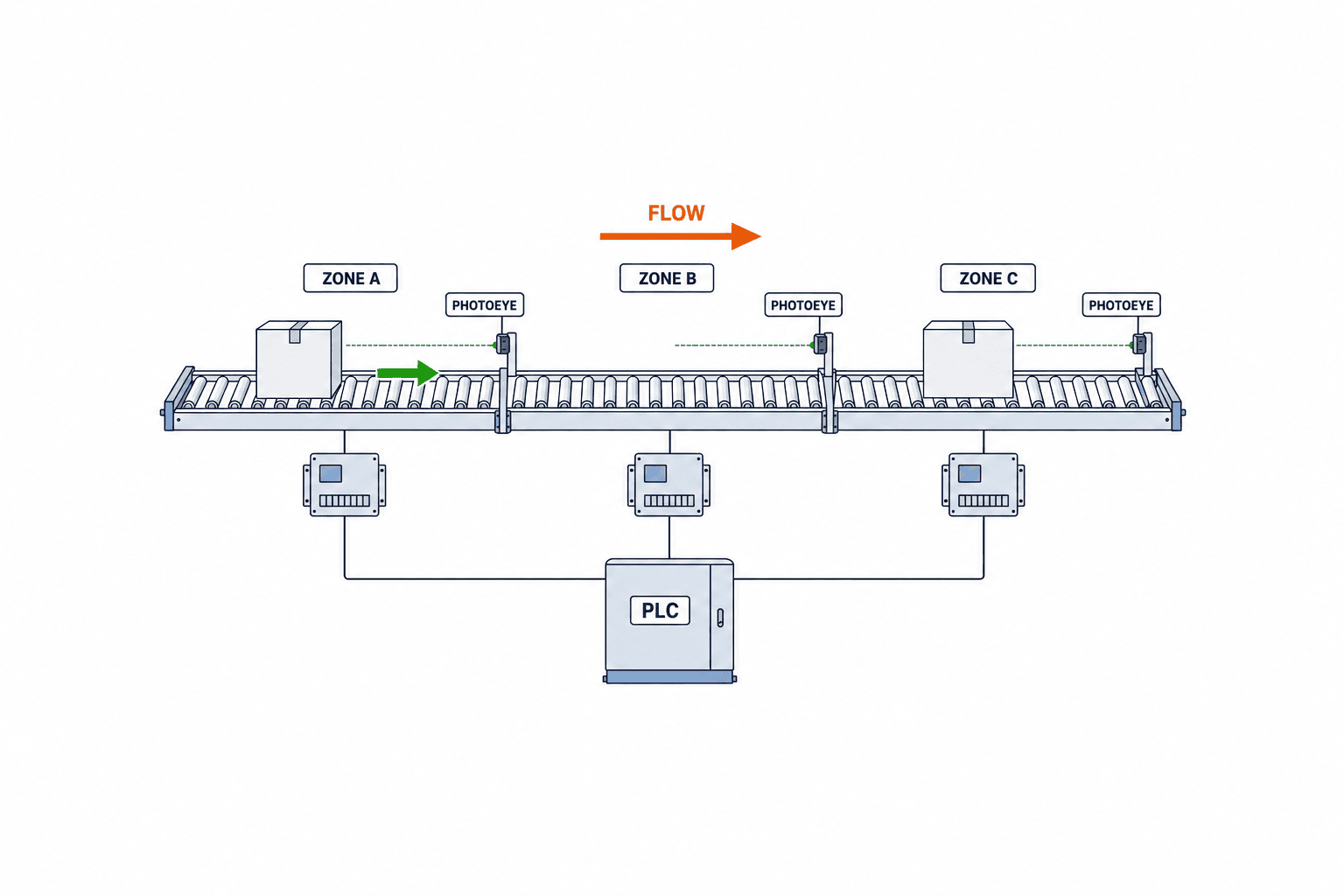
Select sensors and zone control together
The sensor determines both occupancy and the release condition. Hytrol describes retro-reflective sensing with a reflector and diffuse sensing from the product surface [5]. Choice depends on colour, gloss, film, dust, ambient light, guards and cleaning access. Test the hardest product at the intended distance while it vibrates, leans and stops. Observe reflections from adjacent lanes and shifts in lighting.
Write a fault response for a broken wire, dirty lens or missing reflector. A false-empty signal can admit a second carton. A false-full signal can stop the line. Evaluate which failure is more harmful at each point and define alarm, timeout and manual recovery. Hytrol’s maintenance documentation identifies sensor misalignment and reflector damage among causes of an inactive zone, and lens contamination among causes of failure to restart after accumulation [6]. Easy physical access to the sensor can matter more than its purchase price.
Control may be distributed between neighbouring zone controllers or coordinated mainly by a PLC. Both need clear integration with upstream permission, downstream readiness, alarms, operating modes and restart rules. Interroll’s MultiControl AI is an example of a four-zone controller with four drive and sensor connections and fieldbus integration [2]. Hytrol documents distribution of zone-controller signals to a PLC [5]. Four zones is a specification of that device, not a limit for ZPA systems. Avoid duplicating the same release decision in both a PLC and a local controller without an explicit authority rule.
Compare MDR, belt and heavy-load solutions
For cartons and totes, a motor-driven roller (MDR) line is a common candidate. Itoh Denki describes its MDR as a roller containing a 24 V DC brushless motor and explains run-on-demand operation [7]. Zone-by-zone drive can reduce unnecessary running, but a catalogue energy-saving claim cannot be applied to a factory without knowing load, duty cycle, stop ratio and the old system. Belt, chain-driven roller, pneumatic-disengagement and pallet-duty designs may also support accumulation. Select according to underside, mass, positional accuracy, noise, washdown, spare parts, floor layout and the existing drive system.
Thin trays may sag between rollers. Pallets with feet need support where load is actually transferred. A design advertised as “no pneumatics” may still use air at a divert or stopper. List utility requirements across the whole line: power capacity, voltage drop, control-cabinet space, cable routes, air quality and replacement parts. Check IP rating, ambient temperature, corrosion protection and washdown against the exact offered model and installation location. Never generalise a model-specific rating to every ZPA conveyor.
Choose release behaviour for both gap and throughput
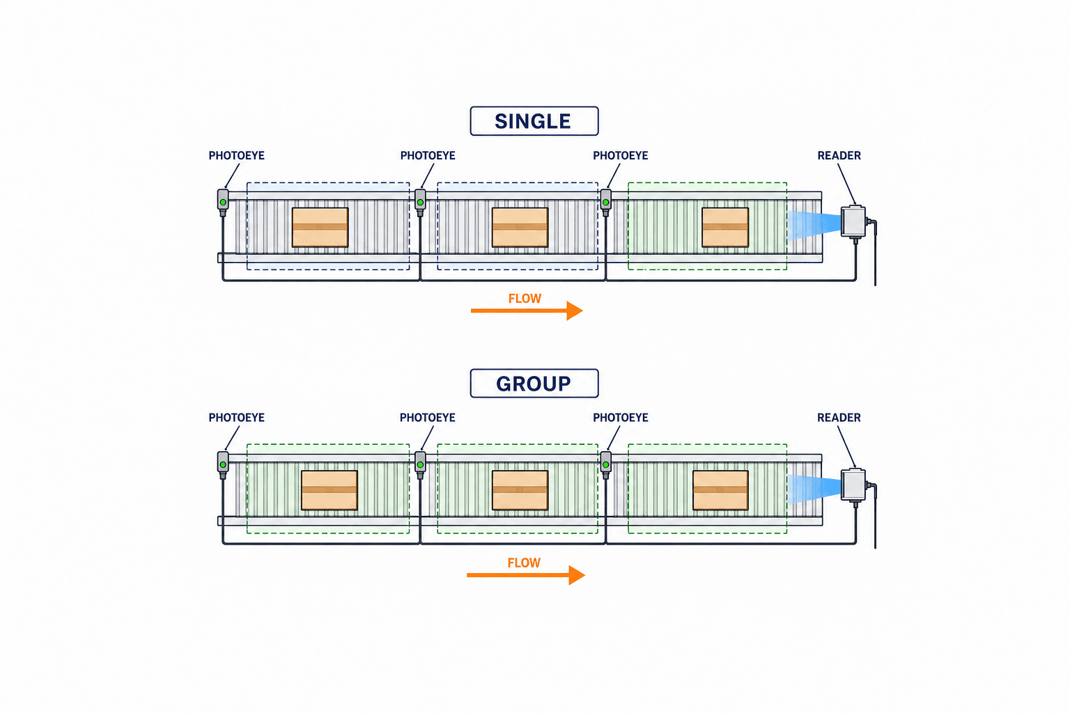
The release mode changes the result. Rockwell Automation’s 44N instructions illustrate singulation and slug release sequences [8]. Releasing several zones together may clear a stored queue faster, but a barcode reader, scale, merge or packing machine may require a controlled inter-carton gap. Define that gap from the downstream equipment’s requirement. “No pressure in the accumulation queue” and “constant time gap at discharge” are separate specifications.
Carton lengths, acceleration, manual removal and changing downstream demand all affect the outlet interval. Where timing is strict, consider a separate metering zone. FAT should use the most demanding mix of real products and measure the achieved gap. A brochure maximum speed or throughput is not an acceptance result for a particular factory.
Calculate with stop scenarios, not averages alone
A simple starting calculation counts arrivals during a downstream stop. If a cartons arrive per minute for t minutes, a×t is a first estimate of newly required positions. If arrivals are bursty, use timestamped logs to find the highest observed arrival count over comparable time windows. Add loads already present when the stop began and subtract zones unavailable for storage. No universal safety factor replaces this evidence.
As an illustrative calculation, 18 cartons arrive in a ten-minute peak and four were already on the line. At least 22 usable waiting positions are needed under that scenario; two outlet zones reserved for a machine function are additional and must not be counted. All figures here are assumptions, not a recommendation for another plant. If upstream can stop, a shorter buffer may work, but production losses shift upstream. Compare these operational alternatives openly.
Also calculate how the queue clears. If downstream capacity barely exceeds ongoing upstream arrivals, the buffer remains occupied for a long time. Approximate net clearing rate as downstream accepted cartons per minute minus upstream arrivals per minute. If it is zero or negative, the queue will not clear without slowing infeed or diverting flow. Test this during commissioning, because the actual gap and downstream handshake may lower the theoretical rate.
Put the stop-and-restart sequence into the RFP
The RFP should list normal transport, downstream blocked, infeed full, removal of the leading load, removal from a middle zone, skewed load, sensor permanently blocked, signal loss, motor fault, power dip, emergency stop and recovery. For each event, state which zones stop, what permission is sent upstream, what the operator sees and whether an authorised reset is required. An example acceptance statement is: “When downstream ready is false, held loads remain separated; when infeed storage is full, upstream permission goes false; when ready returns, loads leave in the original sequence while meeting the specified gap.” Put measured response times and allowed spacing alongside the statement.
A tag list should show operating permission, downstream ready, infeed permission, zone occupancy, drive fault, sensor fault, manual mode, emergency stop state and reset request as applicable. Document signal owner, electrical polarity, state on communication loss, timeout and HMI message. A list of tags without an agreed state transition is not a usable control specification.
Compare quotations on equal scope
Break the quotation into rollers, frame, drivers, sensors, reflectors, cables, cabinet, safety devices, existing PLC changes, installation, commissioning, FAT/SAT, training and spares. “Reuse the existing conveyor” still requires checks of drive transmission, frame openings, sensor mounting and power supply. Compare equipment lead time, imported spare parts, local electrical work and planned production shutdown separately.
Ask each bidder for the same load range, storage count, discharge result, control boundary, local support plan, exclusions and acceptance procedure. A bid with fewer sensors or no PLC integration may appear cheaper while omitting essential work. Our material-handling equipment selection guide explains cross-system RFP and FAT/SAT questions. The additional ZPA-specific questions are one-load-per-zone logic, occupancy sensing, communication between zones, release mode and outlet gap.
FAT and SAT: reproduce the real states
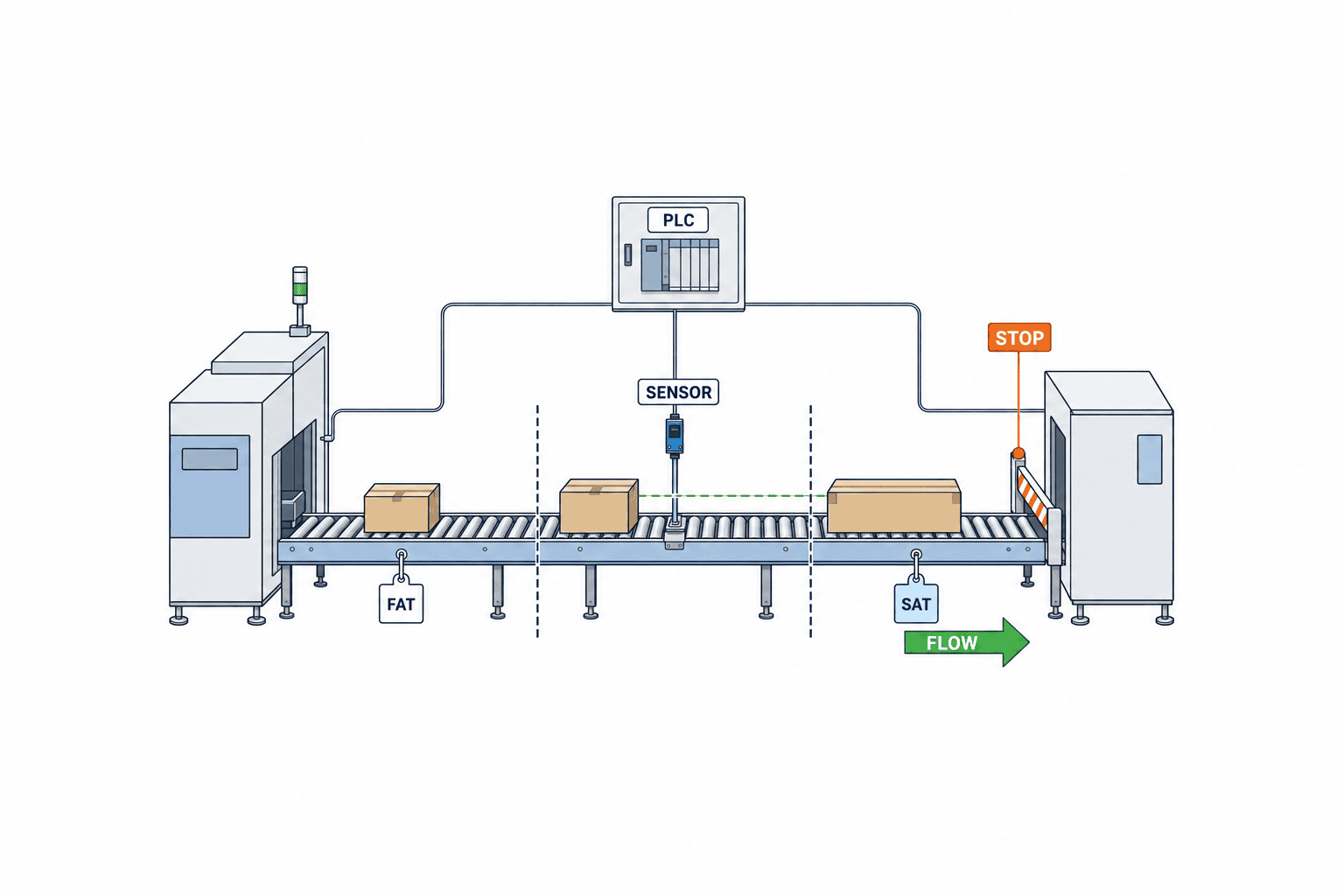
At FAT, test the largest, smallest and hardest-to-sense loads. Start from empty, fill the conveyor, release the queue and remove a load from a middle zone. Repeat skewed or irregular placements. Record stop position in each zone, release time from first to last product, outlet gap, sequence and false detections. Contact/no contact alone is insufficient evidence.
Use controlled fault injection for a blocked sensor, reflector obstruction, lost input, stopped zone drive, communication fault, changing downstream ready signal and power recovery. Risk-assess any test that could create a hazard. Write the recovery steps in the working language: which screen to read, which load to remove and which reset to use. Check that another shift can follow the procedure. FAT is not a substitute for SAT: the real floor, utility, existing PLC timing, humidity and infeed disturbance only appear on site. Agree pass/fail limits before purchase and collect a continuous run with both neighbouring machines.
How to retain acceptance-test evidence
Do not close a test with the single word “pass.” Save the load model, quantity, orientation and mass together with the ambient conditions, operating mode, parameter version, sensor state of each zone and measured discharge times. For mixed sizes, separately test the largest load first, the smallest first and alternating long and short loads. In each stopping-position photograph, identify the sensor and the carton edge used as the measurement reference. That record helps determine later whether a newly introduced product was outside the original scope or whether performance changed after a setting adjustment.
During a continuous run, deliberately create a planned downstream stop. Measure time to fill, the point at which upstream permission is withdrawn and the time to empty after restarting. If operators may remove a load from the middle of the queue, test whether the vacated zone is recognised as empty and whether neighbouring loads advance correctly. Record emergency-stop coverage and the rule that prevents unexpected motion after release in a separate safety test. If a setting is changed during FAT or SAT, keep the failed result, reason, person responsible and repeat-test result. Recheck all cases at the final sensor positions and final software version; a prototype result is not evidence for the delivered configuration.
Safety, maintenance and retrofit boundaries
ZPA control addresses product line pressure; it does not replace guarding against roller pinch points, transfer entrapment or unexpected start. Review guards, emergency stops, energy isolation and restart warnings for the complete machine. OSHA’s conveyor guidance offers examples of safety checks and lockout practices [9], but it is not a substitute for applicable Thai regulations and plant rules. Confirm those requirements locally.
Routine maintenance should check lens and reflector condition, roller rotation, belts, noise, guide tightness and alarms. Prevent operators from bypassing a sensor to avoid a nuisance stop. After replacing a controller, verify address, direction and parameter backup. Record whether a stoppage arose from sensing, drive, control or product variation rather than placing everything under “carton jam.”
A retrofit has five boundaries: mechanical interfaces, electrical capacity, control ownership, safety coverage and maintenance responsibility. Verify frame dimensions and anchoring in the field, not only against old drawings. Agree who adjusts sensors, swaps drivers and changes PLC logic. The line owner, controls integrator and upstream/downstream machine suppliers should approve one handshake table before construction. This prevents two systems from waiting indefinitely for each other’s ready signal.
Five interfaces to verify before modifying an existing line
The mechanical interface includes frame strength, roller shaft ends, drive transmission, floor anchors and transfer height. Matching conveyor width alone does not prove that an MDR can replace an existing roller. The electrical interface includes spare power capacity, voltage drop, cable length, cabinet heat and free terminals. At the controls interface, mark which decisions belong to the existing PLC and which belong to the zone system. At the safety interface, define emergency-stop coverage and the conditions for restart after a stop. At the maintenance interface, assign authority for sensor adjustment, driver replacement and PLC program changes.
If existing drawings are old, survey cabinet wiring, cable numbers, spare I/O and installed dimensions before work starts. Schedule work requiring a line shutdown with production. Have the owners of the upstream and downstream machines approve the same behaviour table before construction. Resolving signal ownership after installation can leave both machines waiting for the other’s permission.
Conditions to reassess when products change
A ZPA line that worked at commissioning may not remain suitable after a packaging change. A new carton length or underside changes zone fit and roller support. Film thickness or printing colour can change the margin of photoelectric detection. Higher mass or a shifted centre of gravity can change coasting and skew. Include the allowable product range in production, purchasing and packaging change control; test products outside that range before routine use.
A downstream software update may also alter the timing of its ready signal. If one section of the line changes speed, remeasure the gaps at both entry and exit. Handover documents should state the qualified load range, the changes that trigger retesting and who may alter parameters. Otherwise, a quality problem months later may be impossible to trace to product, sensor or control changes.
Implementation order and operating KPIs
First collect arrival and downtime logs, product samples and current drawings. Next determine storage count, zone pitch, release mode and handshakes. Compare drive solutions and run an early sensor test with difficult products. Put operating scenarios and FAT/SAT criteria in the RFP, then compare like-for-like bids. Reserve a shutdown window, train maintenance staff, document recovery and stock essential spares before handover.
After launch, track upstream stops due to a full buffer, time spent at full storage, product contact or rubbing, sensor-related false stops, recovery time and spare-part replacements. Use the same measurement definitions before and after the retrofit. A line with higher throughput but more damage may not meet its objective; excessively conservative gaps can starve downstream production. Record each setting change and its reason so recurring faults can be traced.
KPIs beyond equipment uptime
Review those measures by product family during the first weeks, rather than relying on one combined uptime percentage. A ZPA project intended to protect cartons should show the contact and damage trend as well as throughput; a project intended to absorb stops should show how often the buffer fills and forces upstream production to halt. Compare at the same measurement points and with the same event definitions used before installation. Keep a shared fault log with time, affected zone, load type, recovery action and recurrence so different shifts make the same judgement.
The operator guide should include photographs of the actual HMI and conveyor for a full buffer, a load removed from a middle zone, a lost sensor signal and the checks after an emergency stop. Match alarm names to cabinet and screen labels. After cleaning a sensor or updating control software, run representative smallest and largest loads again and keep the result with the change record.
Pre-order checklist
| Question | Evidence to keep |
|---|---|
| How often and how long does downstream stop? | Timestamped events and causes |
| What are peak arrivals? | Carton arrival trace by product |
| What are the limiting loads? | Physical samples and measured underside |
| How many zones fit? | Layout and stopping-position tests |
| What gap and sequence are required? | Release sequence and downstream acceptance |
| Who owns signals? | I/O list and interface drawing |
| What happens on faults and power recovery? | State table and operator instructions |
| How is safety assessed? | Risk assessment and guard drawings |
| How is acceptance judged? | FAT/SAT method and limits |
FAQ on zero-pressure accumulation conveyor selection
Does “zero pressure” guarantee cartons will never touch?
No. It describes preventing line pressure during designed accumulation with the specified loads, zones, sensing and control. Skewed loads, out-of-spec cartons, infeed collisions and sensor faults still require controls and tests. Write a verifiable operating envelope into the contract.
How is ZPA different from a pallet stopper?
A stopper arrests a load at one position. ZPA detects occupancy and coordinates multiple zones for storage and release. They may be combined, but one stopper does not provide zone-wide contact avoidance. Heavy pallets require an appropriate mechanical and drive design.
If there is a PLC, is a zone controller unnecessary?
Not necessarily. Either PLC-centred or distributed control may work. Compare I/O count, cycle time, maintenance capability, communication with the existing line and future expansion. Even with a dedicated controller, the entry/exit handshake and safety responsibilities must be defined.
How many zones should we buy?
Calculate usable storage from stop-time arrival logs and loads already present. Then verify the longest product’s required installed pitch, shortest product sensing and unavailable transfer zones. Separately verify outlet recovery capacity. An average hourly throughput alone cannot answer the question.
What is the price and payback period?
There is no credible universal number. Mass, zone count, reuse of existing equipment, PLC work, safety, installation shutdown and local support change the scope. Measure present downtime, damage and manual handling, then compare quotations on equal inclusions. Count energy or labour benefits only when your own operating conditions support them.
Can SAT be skipped after a successful FAT?
No. FAT proves behaviour under the builder’s test conditions. SAT checks the real site, neighbouring machines, power, communications, loads, safety recovery and shift-team operation. Agree both acceptance stages in the purchase order.
Conclusion
The value of a zero-pressure accumulation conveyor is measured by its ability to hold the required number of loads during downstream interruption and release them in the right order and spacing. Measure arrivals and stops, choose zones and sensors against the limiting products, specify fault transitions, and judge FAT/SAT against written criteria. These steps turn a catalogue feature into a reliable factory buffer.
TOMAS TECH can help a Thai factory review existing-line drawings, physical product samples, buffer requirements and acceptance questions before a drive type or zone count is chosen. If the concept is still open, contact us to discuss the operating conditions.
References
- Interroll, ConveyorControl V3 user manual: https://www.interroll.com/fileadmin/Downloads/User_Manuals/Controls/ConveyorControl/ConveyorControl_V3_EN.pdf
- Interroll, MultiControl AI: https://www.interroll.com/products/controls/multicontrol-ai
- Interroll, ConveyorControl V2 user manual: https://www.interroll.com/fileadmin/user_upload/AMERICAS/User_Manuals/en_ConveyorControl_V2_en_13-07-04.pdf
- Itoh Denki, HBM-604B-UL: https://www.itohdenki.com/hbm-604b-ul
- Hytrol, EZLogic 4.0 manual: https://cdn.hytrol.com/H2-MN-NP-001.1.0_EZLogic4.0_Network_Model_User_Manual_EN-2.pdf
- Hytrol, EZLogic NET maintenance manual: https://cdn.hytrol.com/EZLogicNet-IMM-758-EN-ES.pdf
- Itoh Denki, Motorized Conveyor Roller: https://www.itohdenki.com/what-is-a-motorized-conveyor-roller
- Rockwell Automation, Bulletin 44N instructions: https://literature.rockwellautomation.com/idc/groups/literature/documents/in/44n-in001_-en-p.pdf
- OSHA, Conveyor safety guidance: https://www.osha.gov/sites/default/files/publications/osha3170.pdf


