


An under-ride AGV can enter beneath a cart, lift it and move it between production steps. That simple description hides the real engineering work: the vehicle must fit the actual cart, lift the load without destabilizing it, cross the plant floor, dock repeatedly, exchange signals with equipment, and leave people a safe way to recover a stopped load. Treat the vehicle, carrier, fleet manager, safety functions and plant readiness as one material-handling system.
This guide focuses on under-ride vehicles that lift a cart or dedicated carrier from below. It does not repeat a general AGV overview, towing-train design or conveyor-top AMR integration. Those are different application questions. Start with a short shuttle test using production carts and the real route before comparing catalogue claims.
Start with a production-representative shuttle
Run a complete cycle: request a move, approach the cart, enter beneath it, lift, travel the representative route, dock at the process, hand over the load, leave and return empty. Include the normal load, a near-maximum approved load, an off-centre load, cart dimensional variation, a floor joint, a pedestrian crossing, and at least one deliberately introduced communication or sensor exception. Record each result and the conditions; a successful vendor demonstration is not an acceptance test.
The purpose is to expose gaps between drawings and the plant. A vehicle can drive well while the cart catches on a frame member, the receiving machine cannot detect the load, or operators have no safe recovery method after an interruption. Define what is automated and where human judgment and maintenance intervention remain.
Define the transport unit and work pattern
Document origin and destination, cart types, workpiece dimensions and mass, load count, centre of gravity, production rhythm, replenishment peaks, empty-cart return and shift coverage. Observe queues, temporary parking, changeovers, cleaning and downtime, not just daily trip totals. Decide whether the transported unit is the cart alone or cart plus workpiece, and identify differences between empty and loaded carts.
Use drawing IDs and measured dimensions rather than local nicknames. Record the cart’s underframe, legs, bracing, casters, weld beads, and any changes made in the field. Determine who requests a move, assigns priority, confirms receipt, and authorizes recovery. These operating responsibilities are part of the system requirement.
For the general AGV vocabulary and selection context, see What is an AGV? A practical introduction. This article concentrates on cart compatibility and handover.
Measure clearance as a moving envelope
The height of the vehicle top is only one measurement. Overlay the cart cross-section with the vehicle body, lift, and scanner locations. Check the entry direction, inside leg width, caster orientation, welds, loaded-cart deflection and floor irregularities. Repeat across several carts to capture dimensional variation. Verify clearance during approach, lift and travel, including movement over joints.
Ask what a supplier’s minimum clearance means: which measurement points, load state, lift position and floor conditions were used? Does the stated envelope keep the cart’s legs and casters from blocking the safety scanner plane? Are cart tolerances and floor movement included? Confirm the answer on a drawing and on the actual hardware.
OMRON’s OL-450S application guide gives a model-specific example: it specifies up to 190 mm of clearance beneath the base at maximum lift so carrier casters or legs clear that model’s safety-scanner plane. This is not a universal under-ride AGV requirement. Recheck the geometry for your vehicle, carrier and sensor arrangement.
If carts need modification, review frame stiffness, welds, caster position, centre of gravity, load retention and manual handling ergonomics—not only the open space beneath the cart. Manufacturing, quality, safety and maintenance should review the change.

Standardize the carrier and lifting interface
When several cart designs remain in service, create a compatibility matrix linking cart ID, vehicle, load recipe and handover station. Where practical, define a common carrier interface: entry opening, contact surfaces, lift points and caster reference. Confirm that the lifting pads contact a strong part of the frame, distribute load evenly and cannot slip. Paint, oil, swarf or packaging at the contact point can change the interface.
Determine whether casters lift fully clear of the floor or remain partly in contact. A fully lifted carrier may reduce caster interference but raises the centre of gravity; partial contact may create drag or shift the load during turning. The production-representative shuttle must verify the actual design.
Match lift stroke, stability and handover height
Set lift stroke from floor variation, caster deformation, frame deflection, receiving equipment height and positioning tolerance. The lift height needed to travel without floor contact is distinct from the height needed to place a load at a machine or conveyor. Check tilt, sliding, support footprint and load movement during acceleration, stopping and turning. Define whether travel is interlocked until the lift reaches a safe position.
A rated payload alone does not establish suitability. Review maximum mass, centre-of-gravity envelope, high loads, off-centre loads, empty-cart stability and limits in lifted and travelling states. Ask for the conditions behind every limit. Do not transfer a published number from one model to another or infer payload performance from an unloaded demo.
At the handover station, specify arrival, stop, alignment, receive-complete and exit-permitted signals. Define what happens if the machine cannot accept the load: wait, retreat to a safe buffer, or call an operator. Validate docking across repeated runs, cart variants and route conditions. The equipment’s acceptable offset—not merely the vehicle brochure’s positioning figure—sets the acceptance criterion.
Survey the floor and route
Walk the full route and map joints, steps, damaged coating, grates, drains, metal plates, slope, water, oil, dust and local depressions. Floor conditions affect traction, docking repeatability, vehicle yaw, sensor performance and cart movement. A joint crossed diagonally may create a different disturbance than one crossed squarely. Decide whether to change route, repair the floor or validate a controlled speed and crossing angle.
Test the relevant cleaning and process environment, not only a dry floor. Ask the manufacturer to confirm the permitted temperature, dust, moisture and chemical conditions in writing, then include the required inspection and cleaning in maintenance plans.
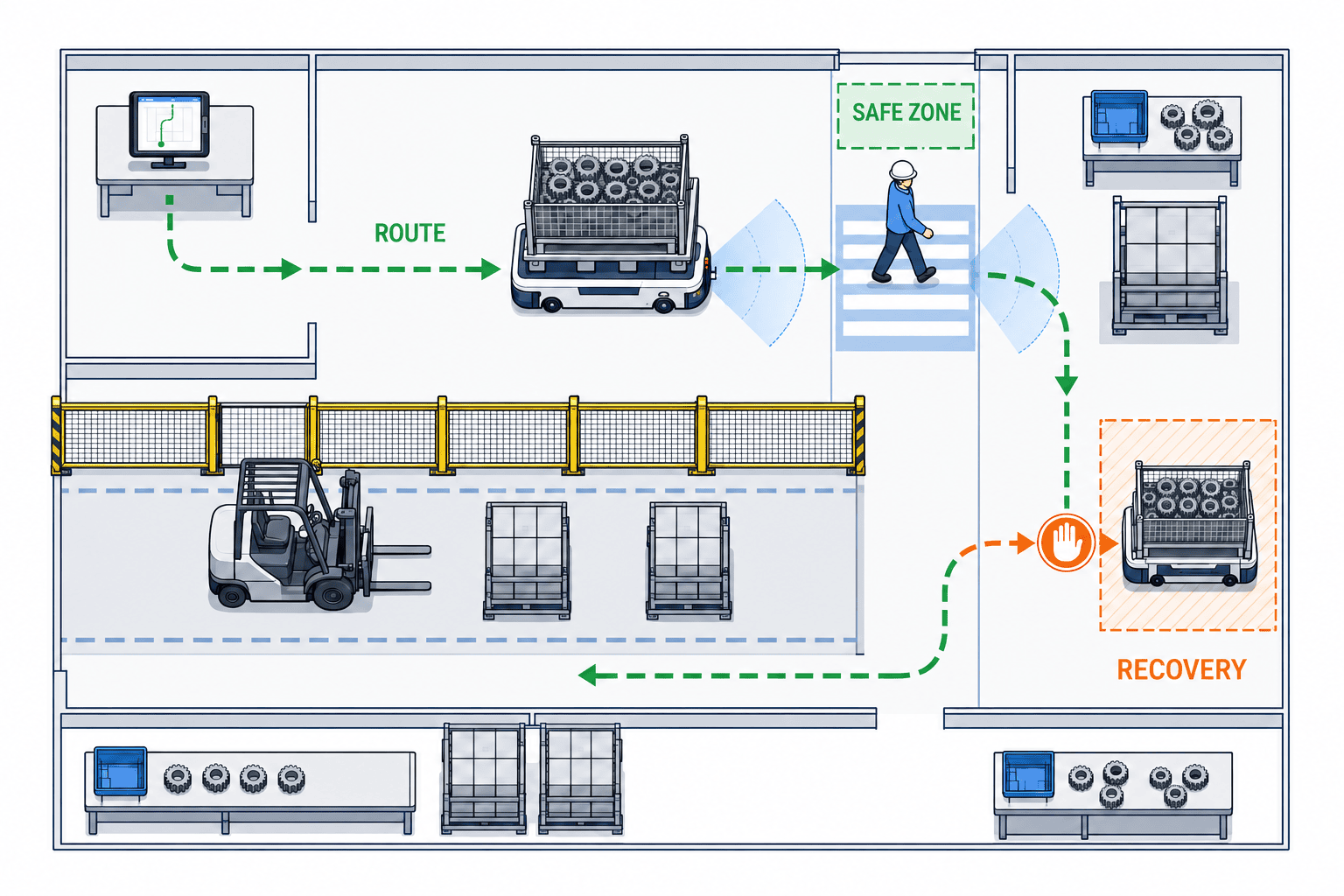
Overlay pedestrian paths, forklifts, tugger routes, emergency exits, equipment doors, temporary material staging and cleaning zones. For each crossing, define right of way, visibility controls, stopping behavior, recovery space and restart authority. Paint alone does not create separation if carts or work in process regularly encroach on the route.

Validate safety with the real cart and load
Cart legs or casters can obstruct a safety scanner. Check empty, approach, lifting, raised, loaded and misaligned conditions, including obstacles behind the cart. If the protective field changes with the load, assess complementary controls such as route separation, equipment protection, speed management or access restriction. Verify stopping performance in the real configuration; it depends on speed, load, floor friction, response time and the stopping circuit.
ISO 3691-4:2023 specifies safety requirements and verification means for driverless industrial trucks and their systems. Its examples include AGVs, AMRs, automated guided carts and under-carts. The ISO page shows the 2023 edition as published and a revision in development. Confirm the applicable edition, local legal requirements and assessment responsibilities for each project.
VDA 5050 is a communication interface between mobile robots and fleet control. Version 3.0, announced on April 20, 2026, adds a zone concept for freely navigating robots and path sharing while retaining predefined trajectories and avoidance corridors. It offers integration options; it is not mandatory for every project and does not replace safety standards or validation. The technical specification explicitly says it is not a safety standard.
Keep safety functions separate from ordinary fleet messages. Document which sensors, circuits, controllers and reset actions establish each protective function. A fleet manager’s ability to send a stop command is not evidence that a required safety stop has been validated.
Define fleet, equipment and exception behavior
Draw the boundaries among vehicle control, fleet manager, MES/ERP or call terminal, receiving equipment, network and safety functions. The vehicle handles local motion and lift control; the fleet manager allocates tasks and manages traffic; business systems request moves; equipment grants handover permission. State ownership and failure behavior for every boundary.
For VDA 5050, specify the exact version, robot and fleet-manager software versions, messages and functions in scope, error handling, compatibility and acceptance tests. A claim of “VDA 5050 support” does not prove that a product supports every feature of a particular version. The 3.0 changes should inform an interface review, not be treated as a blanket compliance requirement.
Model network loss, fleet-manager outage, occupied destination, receiving refusal, load-detection mismatch, interrupted lift, dirty sensor, low battery, manual intervention and duplicate task requests. Specify where the vehicle stops, how it holds the load, who receives an alert and who authorizes restart. Test retransmission and recovery so one request cannot create two deliveries or a false completion.
A stuck vehicle needs a safe, practical recovery procedure. Define manual-mode authorization, load removal support, permitted towing or pushing, lockout, log capture and restart checks. Provide space, tools, training and an escalation path for every shift. Do not assume a vendor’s remote service will be available whenever production runs.
Estimate capacity from measured cycle time
Do not calculate fleet size from top speed alone. Include dispatch, empty travel, entry, docking, lifting, equipment waits, handover, exit, traffic conflicts, charging and charging queues. Measure peak request intervals and the process’s maximum acceptable wait. Record cycle-time distribution, intervention reasons and cart-specific failures, not only the average travel time.
If capacity is short, review route geometry, work leveling, call size, buffers and station handover before raising speed. An investment case should compare like periods and include new monitoring, charging, maintenance and exception-response work. Avoid unsupported savings percentages, made-up payback periods or ROI based only on a sales presentation.
Put measurable requirements in the purchase specification
Include cart drawings and measured variation, workpiece mass and centre of gravity, floor survey, route and crossings, handover height and allowed offset, lift sequence, environmental conditions, duty hours, fleet size and charging plan. List connected systems, interface version, signals, errors, recovery scenarios and log access. For safety, identify applicable law and standards, risk-assessment ownership, scanner configuration, stop validation, manual mode and site acceptance records.
State the deliverables, reviewers and pass criteria rather than naming a standard and leaving compliance undefined. Also agree spare-part availability, local service, response-time definitions, software updates, cybersecurity handling, backup and restore, operator training, manuals, electrical drawings and interface documentation.
FAT and SAT acceptance checklist
| Test | What to verify | Acceptance basis |
|---|---|---|
| Cart entry and exit | Minimum/maximum openings, legs, caster direction | No contact or snagging; enters as specified |
| Lift and load hold | Stroke, approved offset load, retention | Stable under approved conditions; faults recorded |
| Travel and docking | Representative floor, joints, turn and stop | Repeated stop within agreed handover tolerance |
| Scanner coverage | Empty/loaded/raised cases and occlusion | Agreed protective functions evidenced in test records |
| Equipment exchange | Arrival, permission, completion, timeout | Mismatch enters a defined safe exception state |
| Network/power fault | Loss, recovery, low battery, task retry | No duplicate task or unexpected restart |
| Manual recovery | Authority, load support, logging, restart | Trained staff follow the documented procedure |
At FAT, agree the production-representative carts, test loads, routes and signed pass criteria in advance. Log severity, owner, interim control, due date and retest for every issue. At SAT, repeat relevant cases on the actual floor, wireless network, equipment and shifts. Operators should demonstrate dispatch, cancellation, error handling and recovery; attendance at a training session is not proof of competence.
A 90-day pilot example
This is a planning example, not a product lead time or a standard implementation promise. Adjust it to the safety review and plant-change scope.
| Period | Work | Gate or evidence |
|---|---|---|
| Weeks 1–2 | Observe work; survey carts, floor and route; assign owners | Baseline, target process, risk list |
| Weeks 3–4 | Approve carrier geometry, interfaces, safety concept and test plan | Specification and FAT/SAT criteria |
| Weeks 5–6 | Shuttle trial, FAT and exception tests | Issue log and retest records |
| Weeks 7–8 | Site installation, route preparation, training and SAT | Site evidence and operating authorization |
| Weeks 9–12 | Limited-shift operation; measure delays and interventions | Daily logs and weekly review |
| Week 13 | Review operations, safety, maintenance and cost | Decision to continue, change or expand |
Limit the initial route, shifts and load types. Record requests, completions, delays, interventions, stop reasons, load exceptions, near misses and charging. Decide local acceptance thresholds before the pilot. Do not use a generic success number; derive it from production needs and risk. Do not expand while a material safety issue remains unresolved.
Site walk checklist
- Identify each cart and measure more than one example of each type.
- Record underframe, leg opening, casters, workpiece and loaded clearance.
- Check empty, full and off-centre loads and the receiving station geometry.
- Map floor joints, drains, grates, slopes, coating damage and contamination.
- Overlay people, forklifts, tugger trains, emergency exits and staging areas.
- Assign an owner to inspect scanner occlusion and blind zones.
- Define network loss, blocked destination, load mismatch and low-battery behavior.
- Decide who can recover a stopped, loaded vehicle on every shift.
- Agree FAT/SAT cases, evidence, pass criteria and retest ownership.
Open items are not automatically a reason to stop procurement, but they must be named as assumptions with an owner and due date. That makes quotation scope and schedule risk visible.
Common mistakes and questions for suppliers
Common mistakes include choosing from nominal pallet size instead of the actual cart; treating rated load or top speed as throughput; assuming a scanner guarantees safe mixed traffic; confusing a communication interface with safety compliance; and leaving manual recovery to improvisation. Avoid each by measuring the cart, testing peak-cycle behavior, assessing protective coverage, separating interface and safety evidence, and rehearsing recovery.
Ask suppliers: What points and conditions define the clearance figure? Which cart parts can mask the scanner? What centre-of-gravity range is permitted at maximum load? How was docking repeatability tested? Which floor and contamination conditions are excluded? What happens on duplicate requests or a blocked handover? Which VDA 5050 version and functions are actually validated? Who owns the safety assessment and site evidence? How does each shift recover a loaded stuck vehicle? What are the log, update, backup, spare-parts and local-support arrangements?
Tie answers to drawings, test reports and contract scope. Separate current deliverables from future software features or additional engineering.
Thailand integration and final decision
At a Thai plant, verify actual floor, network, shifts, language and maintenance coverage instead of assuming the headquarters standard describes the site. Divide responsibility for cart changes, PLC connection, fleet integration, safety assessment, site tests, training and spares. Thai-German Institute service information lists process improvement, bottleneck analysis, automation and machine design, PLC/SCADA communication and systems integration among its service areas. This is an example of local support capability, not certification of a specific AGV or a guarantee for a project; confirm scope directly.
Compare under-ride, towing and conveyor-top approaches against material volume, layout, cart design, handover and staffing. For related background, see AGV layout design, towing AGV and tugger trains, and integrating conveyor-top AMRs.
Before approval, manufacturing, logistics, engineering, quality, safety, maintenance, IT/OT and procurement should review the same drawings and test evidence. Record any accepted residual risk, interim controls, owner and review date. Include vehicle, carrier, floor, handover equipment, network, safety, training and maintenance in the investment scope. A pilot route does not automatically validate every other route or cart.
The practical decision is based on a production-cart shuttle test, documented FAT/SAT and a bounded pilot. Define cart geometry and lifting, stability and docking, floor and route readiness, scanner coverage, fleet behavior and safe recovery as connected acceptance conditions. VDA 5050 3.0 can broaden integration choices; it is neither a blanket requirement nor a safety standard. Check the applicable ISO edition and local rules separately.
Share the cart drawing, route, load envelope and handover station requirements with our team to discuss a test scope for your Thailand plant: contact TOMAS TECH.


