


If you are planning a PROFINET network diagnostics implementation, starting with a monitoring dashboard’s feature list can leave the central question unanswered: where did the fault occur? When a machine stops, maintenance needs to identify the device, port and adjacent link that deserve inspection. This guide sets out a practical sequence for a factory in Thailand: inventory, diagnostic design, request for proposal (RFP), factory acceptance test (FAT), site acceptance test (SAT), and handover. It does not endorse a particular vendor’s monitoring product.
Define success as an action during an outage
The purpose of diagnostics is to make decisions after an outage faster and repeatable, not merely to add graphs. A generic “IO device not reachable” alarm cannot by itself distinguish a broken cable, loose connector, failing switch port, loss of device power, incorrect device name, or controller issue. Without a defined investigation order and evidence, technicians may have to inspect LEDs one by one.
Write the intended workflow as a sentence: “When the packaging machine on Line A reports a communication fault, the maintenance technician opens its device name in the HMI, checks the topology and neighboring port events, then narrows the field visit to a cable section or device.” Avoid promising a recovery time before knowing the failure cause, access conditions, and spare availability. Instead, measure the time to detect the event, notify the owner, identify the relevant port or device, and preserve evidence during acceptance testing.
Separate diagnostic scope into three layers. The first is alarms and diagnostics from the PROFINET controller and devices. The second is cable, link, switch port and neighbor status. The third is the effect on the machine, production and quality. PI North America’s diagnostics material distinguishes device, network and process error types. A network monitor does not automatically explain production impact; map it to PLC/HMI, maintenance records and, where useful, MES data.
Inventory the physical network port by port
Begin with an as-built inventory, not a purchase order. List controllers, IO devices, drives, HMIs, switches, any wireless bridge, and maintenance access points. Record the machine ID, cabinet, device name, IP address, make and model, firmware, port number, connected port, cable ID and responsible team. IP addresses are only one identifier. PI’s commissioning Q&A explains that an IO device is given a device name and that the controller typically sets its IP address. Confirm the procedure for the actual products and configuration.
Existing plants often differ from their drawings. A bypass cable may have been added during a repair, a small switch installed for an expansion, or a replacement drive connected to another port. Do not classify every undocumented connection as malicious. Confirm its history with production, maintenance and controls, then update the approved as-built drawing. Divide discovery methods into those safe during operation and those requiring a maintenance window. PI notes that active diagnostic tools consume bandwidth and that consumption depends on tool type, placement and polling. Do not run aggressive discovery on an unfamiliar live line without assessment.
The first deliverable should include a port map, not only a device list. “Switch-01/P3 → Drive-07/P1” must lead to a cabinet, cable label and machine position. Otherwise, a P3 alarm is not an actionable instruction. Use the same cable and port IDs on drawings, in the cabinet and on the monitoring screen. Assign ownership for updates after replacement. This port map also provides the reference points for FAT/SAT fault injection.

Establish a topology baseline and verify what LLDP reveals
LLDP allows neighboring devices to exchange identifying information. PI’s commissioning Q&A describes its use in PROFINET for topology discovery, diagnostics and simple device replacement. But “LLDP supported” does not prove that every switch, cabinet position and cable number will appear correctly in a particular monitoring package. Test visibility with the actual devices, switches, software and access permissions. Keep a manual port map for unmanaged intermediary devices, media converters and maintenance connections that the discovery view misses.
Capture an approved baseline while the line is stable. Store expected neighbors and ports, device names, equipment IDs, software and configuration versions, capture time and approver. Later, show changes as newly detected neighbors, missing links or a changed destination port. This helps distinguish an authorized modification from a fault. It also requires change control: otherwise an approved service action or replacement can trigger nuisance alarms, while an unapproved cable change may be accidentally accepted as normal.
Show the control-network boundary and the responsible equipment team on a topology used across several lines. A port event on one cabinet should reach the correct owner. If ERP or MES names differ from machine labels, maintain a mapping; do not create an isolated naming system in the diagnostics tool. In a multilingual plant, keep stable machine IDs, port numbers and alarm codes while translating the human-readable explanations. That limits ambiguity across Japanese, Thai and English shifts.
Choose data deliberately: device alarms, port telemetry and packets
Standard PROFINET alarms and diagnostics are an important entry point for inaccessible devices and communication faults. Link transitions, port counters and changed neighbors belong to the switch and network-management layer. PI North America states that CC-B devices support SNMP, enabling standard tools to read topology information and network statistics. Do not assume every installed device is CC-B; inspect certification, documentation, firmware and the actual available fields. CC-A devices still provide standard diagnostics and topology support, but should not be specified as if they expose the same SNMP detail.
Packet capture is an additional technique when port state does not narrow the cause enough. PI describes port mirroring as copying inbound and outbound data from a source port to another port for diagnosis. It does not follow that mirroring every port permanently is useful. Define which ports may be captured, the trigger, retention, access rights and storage. Assess the added diagnostic device or engineering laptop for network impact, particularly on an existing control network.
Display observations separately from hypotheses. “Switch-01/P3 link down at 10:22,” “Drive-07 unreachable at 10:22,” and “inspect cable section” give a technician a sequence to verify. A definitive “cable broken” message could be misleading if the drive has lost power. Align clocks across controller, switch and monitor; document time synchronization and time zone. The order of events matters when diagnosing intermittent faults.
Switch selection: communication support and diagnostic visibility differ
PI North America explains that PROFINET does not always need a specialized Ethernet switch: its stated minimum switch requirements are 100 Mbit/s IEEE 802.3u and full-duplex transmission. Both managed and unmanaged switches can be used. For port-level fault localization, however, an unmanaged switch’s LEDs may not give the historical or remote evidence a maintenance team needs. Compare managed switches by the SNMP data, LLDP, event logging and port mirroring you will actually use. The sales label “managed” does not prove that the required fields are exposed.
A switch that acts as a PROFINET device may have a GSD file and be recognized by the controller as an IO device. That can help display diagnostics in the control system, but can also expand the scope of PLC configuration changes, alarm engineering and downtime testing. Replacing a switch alone does not complete the diagnostic design. Verify device conformance class, built-in device ports, switch management functions and monitoring software as a system. Check physical constraints too. PI’s commissioning Q&A gives 100 m as the maximum copper cable length between two PROFINET components, while actual designs also need suitable parts, installation and electromagnetic-interference practices.
A staged path is possible where a complete switch replacement is impractical. First clean up PLC/HMI alarms and the port inventory. Add visibility at a boundary switch that supports diagnostics. Replace only the necessary sections during a planned stop. Use incident records to decide whether further monitoring points are justified. Confirm OEM warranty and maintenance requirements before altering wiring.
Fault-localization example: one alarm, different next actions
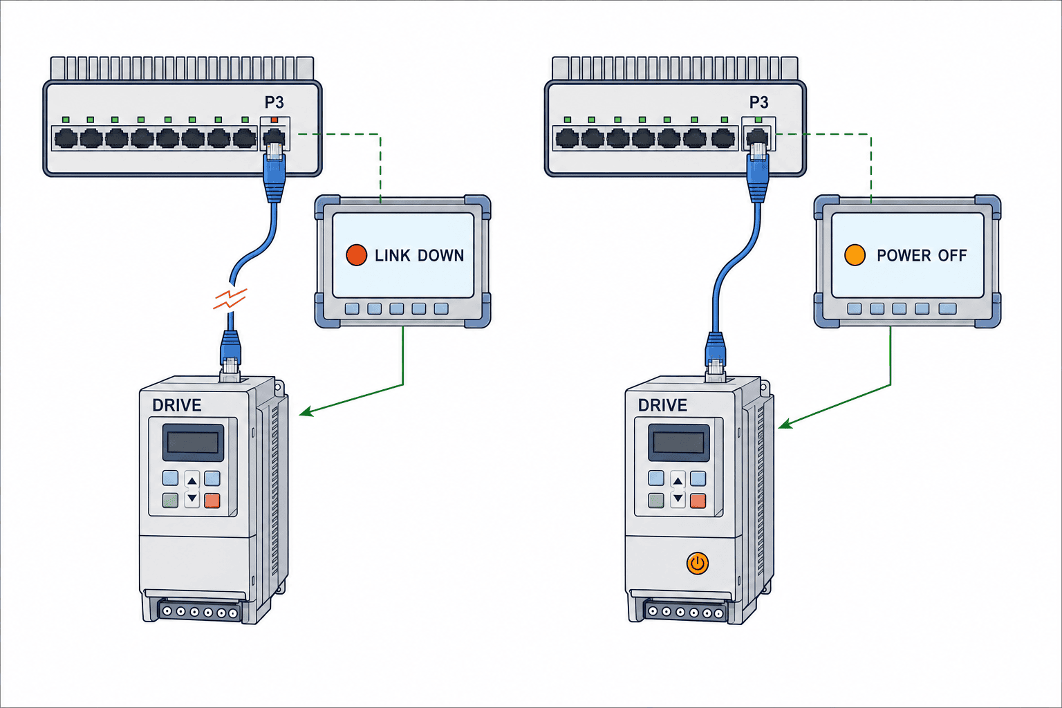
Suppose Drive-07 on a conveyor becomes unreachable while Switch-01/P3 reports link down. Follow machine safety procedures first. Then use the port map and baseline to determine whether P3 connects directly to Drive-07. If it does, inspect drive power, LEDs at both ends, cable and connectors. If P3 feeds a small downstream switch, inspect the other affected devices and that switch’s power. The monitor narrows the field task; it does not replace electrical and machine safety decisions.
Now consider an IO-device alarm while the link remains up. Do not jump straight to a broken-cable conclusion. Check device name, controller configuration, device diagnostics and replacement history. For intermittent communication, compare link-transition history, simultaneously affected devices, port errors and the timing of nearby machinery that may be a noise source. Capture packets only after identifying the phenomenon and relevant port. Keep “observed facts,” “tested hypotheses,” “work performed” and “recurrence check” in separate report fields so the next shift can use the record.
Sometimes the root cause is outside the network: a mechanical jam may stop the line while IO and network communication remain healthy. Knowing that the network was healthy still helps localization. Conversely, production or quality impact requires production records as well as a device alarm. For the relationship between sensor state and production data, see our IO-Link sensor data integration guide.
Write an RFP around evidence and handover deliverables
Avoid asking only for a “complete PROFINET diagnostics system.” State the target machines, operating hours, permitted downtime, existing PLCs, switches and software, network owner and remote-access policy. Then specify observations: device alarms, port link status and history, neighbors, topology changes, timestamps, required counters, HMI or maintenance display, notifications, and evidence export. Ask each bidder to list unsupported items and alternatives.
Require an inventory, approved as-built topology, monitoring-point list, configuration backup, access-control matrix, test record and operating procedure. A dashboard screenshot alone will not let the next engineer reproduce the system. Include port and cable labeling, change-update procedures, account handling and escalation ownership. Name who controls access across the plant-network boundary.
Compare proposals with demonstrations, not feature checkboxes. Ask to see an event for a simulated link break on representative hardware, its display on the topology, and the steps from the alarm to the physical port. State constraints such as mixed vendors, older firmware and invisible cabinet sections beforehand. A CC-B device may expose SNMP while the proposed software still cannot collect the specific item you need. A tool that collects many fields but cannot guide technicians to the right cabinet may add little value.
FAT and SAT: test localization with controlled fault injection
At FAT, test function and reproducibility in a pre-delivery setup with a controller, representative IO device, switch and monitoring screen. Record the normal topology and alarm mapping. Cases can include a safely simulated cable disconnect, device power loss, changed port connection, mismatched device name, and history retention after monitor restart. Perform hazardous operations only in a safe test setup. Approve the fault-injection and recovery procedures in advance.
At SAT, repeat relevant cases on real cabling with actual operators. The test sheet should name the injected event, precondition, expected observation, displayed result, notified owner, route from alarm to port, post-recovery status, evidence file and decision. “Detect a fault” is too vague. “The display and port map both identify the relationship between Switch-01/P3 and Drive-07” is testable. An alarm that points to the wrong port fails the localization goal.
It may be unsafe to reproduce every failure on a continuously running line. Combine prior event evidence, tests during a permitted stop, and comparison with FAT configuration. Record untested cases explicitly and assign the next opportunity to test them. At final acceptance, have a technician navigate from screen to physical asset and use the procedure without the system designer standing by.

Diagnose redundant paths as well as keeping communication alive
Network redundancy aims to keep communication available through a fault, but a successful switchover does not justify leaving a failed link unaddressed. If nobody sees the first failure, the next one can remove the remaining margin. Include the normal path, switchover event owner and restored baseline in the diagnostic plan. Our industrial network redundancy design guide discusses topology choices; here the acceptance question is whether maintenance can identify the failed section in the chosen design.
Distinguish topology changes expected during normal redundancy operation, planned maintenance and device replacement from true anomalies. Give the RFP the actual redundant configuration and require the bidder to specify recorded transitions and notification rules. At FAT/SAT, safely test one path’s failure and recovery where permitted. Check both communication continuity and the human ability to locate the affected link.
Keep the baseline, change control and training current
A deployment is not finished on installation day. A new machine, replacement switch or service laptop changes the topology and possibly the monitoring conditions. Define a workflow that checks impact before modification and updates the port map, drawings, approved baseline and configuration backup afterwards. If any user can freely overwrite “normal,” an unauthorized cable change may enter the baseline. Separate the person making the physical change from the approver of the new baseline and retain history.
Review alarms by whether they led to an action, not by their volume. Sample events where technicians could not identify the next physical check; improve naming, priority or the port map. Correlate multiple alarms from one incident so the earliest observation and downstream effects are visible. After changing diagnostic rules, repeat selected FAT/SAT cases as regression checks. Respect OEM and plant procedures when modifying control configurations.
Train on three situations: device missing, link healthy but device alarm active, and several devices failing together. First navigate the approved drawing to the real cabinet on paper; then use a permitted stop for field practice. In a multilingual factory, share short equipment IDs, port IDs and alarm codes across languages while translating the explanatory text. Handover must cover who may edit settings and who contacts the supplier, not just who can log in.
Phase the implementation and preserve decision evidence
Start with one asset that frequently alarms and one whose communication loss has a large effect. This gives representative cases without extending a new tool across the whole plant at once. Use as-built drawings, alarm history and interviews to pick one past incident that took too long to localize. Test how far port-level observation would have narrowed the search.
Next, explain every missing observation: is it the switch, endpoint, permissions or collector configuration? Decide on added hardware only after this gap is documented. Then make baseline updates and alarm handling part of routine maintenance. Compare the same test scenario before and after by the steps and time required to reach the target port and by the quality of evidence, rather than claiming an unmeasured percentage reduction in downtime.
Request separate cost lines for monitoring licenses, switches, configuration, site testing, training and upkeep. Determine who makes changes when assets are added. Long-term cost depends partly on whether the plant can maintain the delivered drawings and configuration without the original integrator.
Protect diagnostic data and include access control in acceptance
Diagnostic records can include machine names, IP addresses, network topology and outage times. If maintenance laptops or external support staff will view them, define who may read data, change settings and export files. Separate viewer and administrator rights, and require identifiable operation logs in the RFP. Where a product only supports shared accounts, agree on an alternative audit method.
Packet captures and topology exports help investigate faults, but also reveal plant architecture outside the factory. Specify storage location, retention period, deletion owner and who approves sharing with a vendor. For a cloud-connected proposal, ask exactly which data leave the site, over which path, where they are stored, and what remains available if the connection fails. Apply the factory’s information-governance policy. Document only the necessary traffic across the boundary between control and business networks.
Plan for failure of the monitoring system itself. Even if its screen is unavailable, technicians should be able to make an initial assessment using PLC/HMI standard alarms, an offline port map and plant safety procedures. During FAT, test how events appear after a monitoring-server restart or connection outage; record any gap. Decide who receives notice that monitoring has stopped. A helpful tool should not become the sole way to investigate a line.
FAT/SAT logs can also support later improvement, but temporary test settings and test accounts should not survive handover. Put removal of temporary settings, reconciliation with the production access matrix, configuration backup and a technician-led recovery check on the acceptance sheet. These conditions help keep the diagnostic capability maintainable after the integrator leaves.
Tell field teams that the monitor reports the state of observed sections, not every possible cause. A blank view is not proof of a healthy network: the section may be outside scope, access may be insufficient, the collection path may be broken, or the collector may be stopped. Mark monitored and unmonitored sections on the equipment drawing and approve the gaps at acceptance. For future expansions, register the port and its owner before adding the new device to monitoring, then add a test case so visibility grows with the plant.
Frequently asked questions
Does a PROFINET network diagnostics implementation require replacing every switch?
Not necessarily. Both managed and unmanaged switches can carry PROFINET traffic. Where remote, port-level event history is required, check whether the installed switches provide it. Define the faults and evidence first, then consider replacing only deficient sections. Built-in device switches and unmanaged intermediates may still need a manual map and field inspection.
Can an LLDP topology view replace the cable register?
No. LLDP helps discover neighbors, but it does not necessarily identify the physical cable ID, routing inside a cabinet or equipment ownership. Maintain physical labels and a port map, then reconcile them with discovered neighbors.
How do CC-A and CC-B affect diagnostic design?
According to PI North America, all PROFINET devices support standard alarms, diagnostics and topology, while CC-B adds SNMP support for reading statistics and related data. A conformance class alone does not guarantee every required field on the chosen dashboard. Test the precise device, firmware and monitoring-software combination against the RFP.
What should FAT/SAT acceptance criteria contain?
Check that the injected event matches the displayed device, port, time and recipient, and that a technician can reach the physical asset using the map. Confirm recovery display and evidence export. Mark any unsafe-to-test case as untested and schedule a suitable future test.
Can a monitoring tool affect an existing production network?
It depends on its design. PI explains that active tools consume bandwidth according to tool type, placement and polling. Limit the initial readout, then verify load and alarm behavior in FAT or a safe site window.
Conclusion: define the port and the maintenance action before procurement
A PROFINET network diagnostics implementation includes more than a monitoring screen. Align the equipment and port register, preserve an approved topology baseline, combine device alarms with switch-port information, and prove fault localization during FAT/SAT. Change control and training make the result usable on an overnight shift. Beginning with one line and a clear fault scenario makes the needed equipment and ongoing work visible.
If you are planning visibility or a retrofit for a factory in Thailand, you can contact TOMAS TECH even before the as-built drawing is complete. The target line, recurring communication alarms and permitted stop window are enough to begin defining a survey and test scope.


