


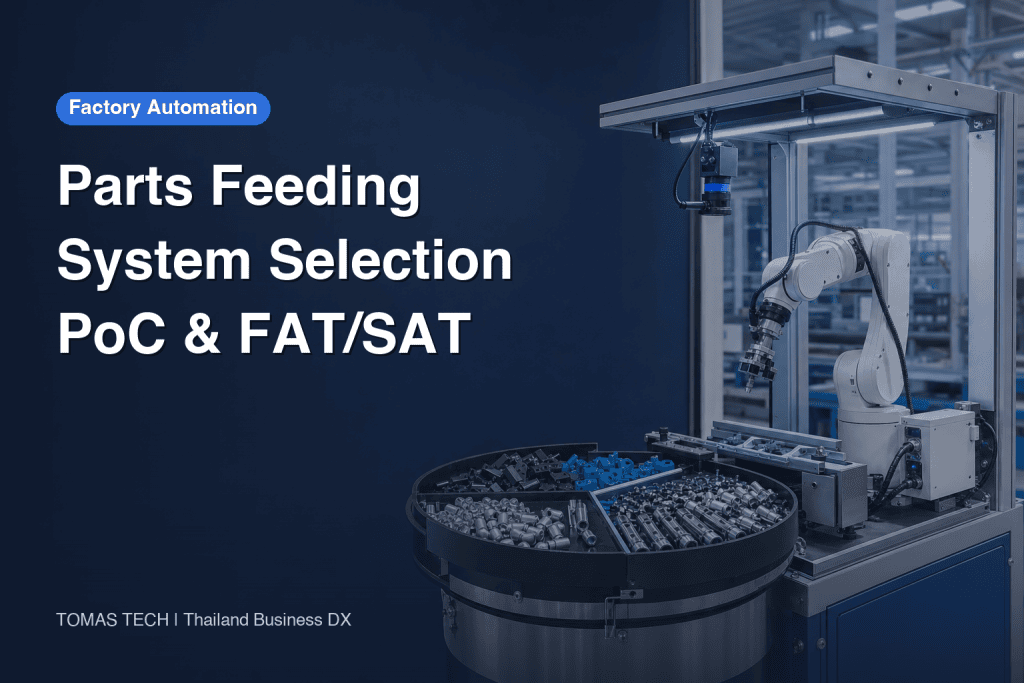
Searching for a parts feeding system often turns into a comparison of feeder speed, supported dimensions, bowl diameter or camera resolution. For a stable automated assembly line in Thailand, however, the useful unit of selection is not the feeder alone. It is the feeding cell: replenishment, presentation, recognition, gripping, recirculation, downstream handoff and abnormal recovery. This guide compares conventional bowl feeders, flexible feeders with 2D robot vision, 3D bin picking, and tray/pallet feeding, then connects the choice to an RFP, a real-part proof of concept (PoC), factory acceptance testing (FAT), site acceptance testing (SAT), and a variable-based TCO/ROI model.
Treat the parts feeding system as a cell, not a machine that merely aligns parts
The purpose of feeding is not to make every part look orderly. It is to deliver the correct part to the downstream process at the required time, pose, location and quality. If the project boundary stops at the feeder outlet, important losses disappear from the specification.
A feeding cell normally includes at least:
- a hopper, box or tray that receives and buffers parts;
- upstream replenishment and low-level detection;
- separation, untangling, reorientation, alignment or random spreading;
- 2D/3D robot vision and lighting;
- a robot or axis mechanism;
- a vacuum tool, gripper, chuck or automatic tool change;
- recirculation or rejection of failed picks, overlaps and wrong-side-up parts;
- handshakes with assembly, inspection or packaging equipment;
- safety devices, controls, recipes, history and recovery screens.
This boundary exposes situations such as “enough parts are visible, but the robot cannot approach them,” “the pick works, but recirculation damages the surface,” or “the demo runs until a hopper refill changes the pose distribution.” Those are system risks, not minor commissioning details.
Measure effective output, not a catalogue maximum
A useful conceptual model is:
Effective output = recognizable presentations × pick attempt rate × pick success × good handoff rate − losses from recovery, refill and changeover
This is not a universal guarantee equation. It is a way to define project measurements. Every factor must be tested using actual parts, lighting, tooling, robot motion, fill level and operating conditions. Record sustained average performance, variation and long-tail stoppages, rather than quoting only a short peak.
A part-family matrix comes before part feeder selection
Do not begin with a model number. Begin with the complete part family. Drawing dimensions alone are insufficient because behavior can change with production lot, supplier, oil, burrs, static charge, humidity and storage.
Build a matrix with at least the following fields:
| Field | What to record | Design impact |
|---|---|---|
| Part number/revision | current and planned variants | recipes and future capacity |
| Envelope/mass | minimum, maximum, center of gravity | feeder, tool and robot payload |
| Material/surface | metal, resin, transparent, reflective, dark | lighting, sensing and vacuum |
| Condition | oil, powder, moisture, static | sticking, double picks and cleaning |
| Shape risks | nesting, overlap, rolling, entanglement | separation, plate and finger design |
| Quality limits | scratches, dents, deformation, contamination | contact material and recirculation |
| Required pose | face, angle and location accuracy | vision, flipping and fixtures |
| Production | takt, hours, mix ratio | buffer, parallelization and changeover |
| Packaging | bag, box, bulk or tray | replenishment, labor and logistics |
Do not merge parts simply because they look similar. Preserve differences that affect visual discrimination, tool access or entanglement. If only prototypes exist, state that their surface and tolerance distribution may not represent mass production, and add a production-part revalidation gate.
Comparing four parts feeding methods

1. Conventional bowl feeder
A vibrating bowl uses dedicated tracks and selection features to present parts in a controlled pose. It remains a strong candidate for stable, long-running production of a well-defined part. Mechanical pose constraint can make downstream pickup straightforward.
The trade-off is that a new part or geometry change may require track or tooling modification. Entanglement, cosmetic damage, noise, dimensional variation and oil-dependent friction must be checked with real parts. A high rate on one dedicated part is not automatically the best total productivity for a high-mix plant.
2. Flexible feeder plus 2D robot vision
Parts are spread on a flat surface, moved or flipped by vibration, located by an overhead camera and picked by a robot. The attraction is recipe-driven product change, less dedicated track tooling and integrated vision/robot operation.
OMRON describes its iPF series as using three-axis vibration, modular feeder and hopper sizes, and integration with OMRON robots, vision and ACE software. Its lineup page lists iPF-240, iPF-380 and iPF-530 and shows an update date of December 1, 2025. These are vendor catalogue statements—not proof that a given part meets its takt. Transparent, reflective or black parts, shallow edges, oil films and overlaps still require an application PoC.
OMRON likewise positions AnyFeeder as a vision-and-robot solution for varied parts and frequent changeovers. Vendor positioning should be separated from project evidence that a defined production lot operates reliably at the required rate.
3. 3D bin picking
A 3D sensor finds randomly piled parts in a box or bin and guides a robot while collision constraints are considered. It can reduce dedicated alignment equipment and may feed directly from bulk packaging. Suitability depends strongly on shape, reflectivity, pile geometry, bin walls, robot reach and gripper approach.
ABB presents FlexLoader as a functional module for pallet, bin and conveyor feeding with 2D or 3D vision. ABB states that more than 1,200 systems have been installed worldwide; that figure is an ABB claim and does not establish a universal success rate or ROI. ABB’s 2026 product manual describes a 2D/3D sensor identifying part position and orientation and sending the data to the robot.
Testing must include the difficult end of the bin: wall-adjacent parts, deep overlaps, changing piles after each pick and the nearly empty state. A successful first set of picks does not prove good bin-emptying behavior.
4. Tray or pallet feeding
Parts arrive in defined pockets or patterns. This can reduce uncertainty for delicate, easily tangled or pose-critical components. Known coordinates do not eliminate the need to detect tray warp, pocket tolerance, stack offset, empty pockets, wrong parts or reverse loading.
The cost boundary extends beyond the cell. Trays may need preparation, cleaning, return logistics, storage and supplier agreements. Low equipment complexity can be offset by higher logistics labor and dedicated packaging inventory.
Selection matrix
| Criterion | Bowl | Flexible + 2D | 3D bin | Tray/pallet |
|---|---|---|---|---|
| Product change | dedicated tooling may dominate | often recipe-friendly | model/tool/bin validation | tray and recipe change |
| Random bulk input | often suitable | spreads parts in a plane | feeds directly from a bin | requires upstream ordering |
| Damage/tangling | validate tracks and recirculation | validate vibration and recirculation | validate contact and drops | easier to control, logistics-dependent |
| Vision dependency | may be low | high | high | low to medium |
| Changeover work | may include mechanics | recipe, plate and tool | model, tool and bin | tray and recipe |
| Upstream logistics | bulk | bulk | bin/box | ordered presentation |
This is not a universal ranking. Use it to shortlist perhaps two methods against the part-family matrix, then compare them in a controlled PoC.
Robot vision selection is about controlling image conditions
Robot vision performance does not come from megapixels alone. Contrast, lighting angle, diffusion, polarization, exposure, external-light shielding, vibration settling, part height, lens contamination, oil and dust all change the image distribution.
The PoC should record:
- candidate count, confidence, false detection and missed detection per image;
- treatment of overlaps, touching parts, partial views and plate edges;
- parts that are visible but inaccessible to the gripper;
- lighting, exposure, lens and working distance;
- daylight, factory-light flicker and clean-versus-dirty conditions;
- who adjusts what during a recipe change;
- whether images and decision logs remain available for troubleshooting.
For transparent or reflective parts, evaluate backlight, diffuse light, polarization, silhouette or multiple exposures where appropriate. Added optical complexity also adds maintenance conditions, so the PoC deliverable must include a repeatable field adjustment procedure.
Select the robot gripper for the entire motion and failure cycle
Vacuum, parallel grippers, three-jaw chucks, internal gripping, magnetic tools and soft grippers each have a place. The question is not whether one clean sample can be held. The tool must pick from allowed presentations, withstand acceleration, insert or place correctly, avoid damage, detect failure and release safely.
Evaluate:
- allowed and forbidden gripping surfaces;
- holding variation caused by tolerance, oil, dust and temperature;
- double-pick, jam and no-part detection;
- collisions with nearby parts, feeder surfaces and bin walls;
- life and replacement of tubes, cables, connectors, fingers and cups;
- change time and poka-yoke for wear parts;
- tool change and recipe verification in mixed production;
- dropped-part recovery and quality quarantine.
Robot payload alone is not enough. Verify tool mass, center of gravity, posture, acceleration, moment and hose forces against the selected robot’s official limits.
An RFP table that makes proposals comparable
An RFP should permit creative method proposals while standardizing the boundary and evidence. Do not write only “x parts per minute.” Pair each requirement with conditions, measurement, acceptance and exclusions.
| ID | Requirement | RFP content | Acceptance evidence |
|---|---|---|---|
| FR-01 | part scope | number, revision, lot, state, future parts | part-family matrix |
| FR-02 | output | downstream takt, average/peak, buffer | timestamped cycle log |
| FR-03 | quality | pose, location, damage, wrong/double part | inspection record and images |
| FR-04 | refill | package, batch size, frequency, low level | refill test and log |
| FR-05 | changeover | parts, tooling, recipe, operator | measured change record |
| FR-06 | recovery | jam, no candidate, drop, communication loss | fault-injection evidence |
| FR-07 | integration | upstream/downstream I/O and traceability | I/O list and sequence |
| FR-08 | safety | cell boundary, access and maintenance | risk assessment and validation |
| FR-09 | maintenance | consumables, cleaning, backup and training | maintenance/training records |
| FR-10 | data | run, stop reason, image and recipe history | sample logs and restore test |
List robot, gripper, vision, lighting, feeder, hopper, safety, controls, transport, installation, training, spares, FAT, SAT and ramp-up support, marking each item included or excluded. If incentives are part of the business case, verify the latest BOI conditions for the individual project; do not assume a rate, deadline or eligibility from a general article.
Designing a real-part PoC

A PoC is not a showroom demonstration. It converts uncertainty into a decision. Apply the same requirements and sample plan to each candidate and keep failure data.
Part lots
Separate normal lots, tolerance-edge samples and different surface states. If production parts are unavailable, do not bury that gap in a pass result—create a production-part revalidation gate. Include identified acceptable-limit parts and defects the system must reject.
Initial pose and loading
Test after realistic box dumping, with skewed concentration, overlap, nesting, entanglement and biased face-up/face-down distribution. Photograph the initial state so competing methods face comparable difficulty.
Lighting and surface
Record lighting recipe, shielding, exposure, polarization and backlight. Test oil, dust, fingerprints, small scratches, color difference and transparency. Re-image after planned continuous running, not only after cleaning.
Feed quantity and recirculation
Test minimum, normal and maximum expected fill. Separation and collision behavior changes with density. Track how often a part recirculates and whether repeated motion creates scratches or deformation.
Takt and downstream handoff
Measure from downstream request through recognition, pick, orientation correction, handoff and completion. Include downstream stops, restart bursts and hopper refill. Record median, slow-tail cycles, stop count and accumulated stop time, not only the average.
Abnormal recovery
Deliberately inject zero candidates, repeated pick failure, double picks, drops, empty hopper, overload, camera communication loss, robot stop, safety-door opening, power restart and wrong recipe. Evaluate recovery success, time, permission, quarantine and traceability.
Minimum PoC report
- objective and unresolved questions;
- sample list, lot, quantity and condition images;
- hardware/software configuration and versions;
- lighting, camera, tool, speed and fill settings;
- procedures mapped to requirement IDs;
- raw logs, images, video and stop reasons;
- pass, conditional pass, fail or not-tested decisions;
- changes and retest scope;
- residual production risks and owners.
There is no universal number of parts or hours that proves stability. Lot variation, pose distribution, cleaning cycle and dependent failures determine the necessary test plan.
Make FAT/SAT a requirement-to-evidence chain

FAT and SAT should not be last-minute speed demonstrations. They continue the evidence chain created in the RFP:
Requirement → Test → Evidence → Decision → Retest
For FR-06, for example, define the injected repeated-pick failure, operator access, recovery procedure, quality quarantine and timing method. Combine video with timestamped PLC, robot and vision logs. If a design change affects the requirement, retest it rather than automatically carrying forward the earlier pass.
FAT scope
- approved drawings, BOM, software versions and backup;
- continuous feed and handoff by part family;
- changeover, recipe verification and wrong-part prevention;
- replenishment, recirculation, empty/full and stop/restart;
- abnormal modes and safety-function validation;
- logs, reports, alarms and access control;
- spares, manuals and maintenance training.
SAT scope
- actual floor, power, air, lighting, climate and network;
- end-to-end takt with upstream packaging and downstream machine;
- refill, changeover and recovery by plant personnel;
- alignment with site access and lockout procedures;
- post-shipping calibration, robot frames and camera position;
- actual production lots and quality decisions.
ISO 10218-1:2025 addresses safety requirements for the industrial robot itself, while ISO 10218-2:2025 addresses industrial robot applications and robot cells. This scope split helps explain why a compliant robot does not complete cell validation. The project still needs a risk assessment and review of applicable standards, Thai legal requirements, plant rules and customer requirements.
Define abnormal modes before design freeze
| Mode | Detection | Automatic action | Human action | Evidence |
|---|---|---|---|---|
| low parts | level/candidate count | request refill or controlled stop | refill and verify | level history |
| overfill | height, weight or image | inhibit refill | remove and restart | alarm log |
| nesting/overlap | image or load | separate/recirculate | isolate and clean | failure images |
| pick failure | vacuum, grip or image | limited retry | inspect tool | attempt log |
| double pick | thickness, weight, image | reject | quarantine | inspection log |
| dropped part | sensor or trajectory | safe stop | recover and inspect area | event log |
| camera fault | communication/image quality | stop and reconnect | clean/recalibrate | diagnostic log |
| wrong recipe | identity check | inhibit start | select correct recipe | change history |
| downstream stop | handshake | buffer or wait | remove cause | I/O history |
Unlimited retries can hide takt loss and part damage. Define retry limits, circulation limits, reject destinations, quality decisions and restart authority.
Compare TCO and ROI with variables, not universal prices
Price depends on parts, method, output, safety boundary, site work and validation. Use the same system boundary for every candidate.
TCO = C_equipment + C_engineering + C_tooling + C_safety + C_installation + C_validation + C_training + C_spares + C_maintenance + C_energy + C_floor + C_changeover + C_quality + C_downtime + C_logistics
Initial cost includes the feeder, robot, gripper, camera, lighting, controls, safety, engineering, PoC and FAT/SAT. Operating cost includes cleaning, consumables, adjustment, changeover, tray logistics, downtime, damage, scrap, spares and software support. Use the same period, currency, exchange-rate assumption and residual-value policy.
Annual benefit = direct labor reduction + incremental contribution from additional output + quality-loss reduction + downtime-loss reduction − added annual operating cost
Simple payback = initial investment / annual benefit when annual benefit is positive.
ROI = (cumulative benefit over evaluation period − initial investment) / initial investment
Label inputs as current actuals, measured test data, supplier quotations or management assumptions. Confirm that labor can actually be removed or reassigned, that demand exists for added output and that quality savings match accounting records. Run sensitivity on takt, utilization, mix, changeovers and downtime.
A gated path to robotic assembly automation
- Measure the current process: manual cycle, waiting, quality, mix and stops.
- Freeze the part family: scope, exclusions, future parts and change rules.
- Compare methods: shortlist from the four approaches with common boundaries.
- Issue the RFP: standardize requirement IDs, evidence, scope and responsibilities.
- Run a real-part PoC: include difficult lots and injected failures.
- Freeze design: incorporate PoC conditions, residual risk and change control.
- FAT: verify function, safety, output, recovery and documentation.
- SAT: reverify site conditions, interfaces, people and production parts.
- Ramp and improve: use stop reasons and images under controlled change management.
For the wider production strategy, see High-mix, variable-volume automation in Thailand. For responsibility boundaries and local commissioning, see How to select a robot system integrator in Thailand.
Questions to ask every supplier
- Which part and lot is most difficult, and what remains untested?
- Under what fill level, pose distribution and continuous period was output measured?
- How are failed picks and recirculation counted in the rate?
- What evidence determines cleaning and replacement intervals?
- What changes in mechanics, tooling, vision and PLC when a part is added?
- Who can edit recipes, and how are differences, backup and restore controlled?
- Who supplies FAT/SAT samples, when and in what condition?
- Where is responsibility divided for safety design and validation?
- How are correction, retest, schedule and additional cost handled?
- Who provides local support, spares, remote assistance and training?
Industry scale is useful context. IFR’s World Robotics 2025 reports 542,000 industrial robot installations globally in 2024, with Asia accounting for 74% of new deployments. Those figures are not Thailand installation data and do not prove the economics of any one cell. Market momentum must remain separate from technical feasibility and business-case evidence.
FAQ
What is a parts feeding system?
It is the equipment and controls that deliver parts from bulk, boxes or trays to a downstream process at the required pose, location, time and quality. In practice, specify replenishment, vision, robot gripper, recirculation, integration, recovery and safety as part of the cell.
What should come first in part feeder selection?
The part-family matrix and system boundary. Record lots, dimensions, material, oil, static, tangling, cosmetic limits, packaging, takt and changeover, then include the difficult conditions in the PoC.
Should robot vision be 2D or 3D?
2D is often a candidate when planar location and rotation are sufficient. 3D becomes relevant for height, piles and random bin poses. Reflection, occlusion, accuracy, cycle, reach and tool collision still require real-part testing.
Vacuum or mechanical gripper—which is better?
It depends on surface, porosity, oil, deformation, insertion force and drop risk. Evaluate double-pick and no-part detection, interference, consumables and safe failure—not only holding force.
How many parts should a robotic assembly PoC run?
There is no universal count. The test must represent lot variation, pose distribution, dependent failures, cleaning, refill and changeover. Representative conditions matter as much as sample size.
What is the difference between FAT and SAT?
FAT verifies the built system in the supplier environment. SAT reverifies it with actual utilities, interfaces, operators and production lots at the installation site. Both should trace evidence back to RFP requirement IDs.
How should price and ROI be compared?
Compare total cost across engineering, tooling, vision, safety, installation, validation, changeover, maintenance, quality, downtime and logistics. Separate measured inputs from assumptions and run sensitivity analysis.
Does an ISO 10218-1 robot make the complete cell safe?
The robot and the integrated application have different scopes. ISO 10218-1:2025 covers industrial robots; ISO 10218-2:2025 covers industrial robot applications and robot cells. The cell still needs risk assessment and validation.
Conclusion: select the feeding cell through requirements and evidence
Do not select a parts feeding system on catalogue maxima or feeder price alone. Define the part family, feed stability, vision, pick success, recirculation, damage, tangling, oil, static, changeover, replenishment, downstream takt and recovery as one feeding cell. Compare bowl feeding, flexible feeding with 2D vision, 3D bin picking and tray/pallet feeding, then connect the RFP to real-part PoC, FAT and SAT evidence. That process makes production risk visible before it becomes a commissioning dispute.
If you are comparing feeding methods for a Thai factory or preparing an RFP and real-part PoC, contact TOMAS TECH. A discussion can begin from the parts and plant constraints even before the feeder or robot brand has been selected.
Primary and official references
- ISO, ISO 10218-1:2025
- ISO/TC 299, Robotics standards catalogue
- IFR, World Robotics 2025
- OMRON, iPF Series lineup
- OMRON, iPF Series features
- OMRON, AnyFeeder robotic solution
- ABB, FlexLoader Feeding Functional Module
- ABB, FlexLoader product manual (2026)


