



A factory can record every shot and still face an unplanned mold repair. It can archive cavity pressure or press force traces and still be unable to say whether a change came from the mold, the machine, the material or a setup. Before buying “AI mold life prediction,” define the decision: which mold component, which failure mode, how much warning, and what maintenance action would the warning change?
This guide is for production engineering, tooling maintenance and quality teams in Thai injection molding and metal stamping plants. A mold management system tracks ownership, location, loaned tools, shots and service records. The present topic goes further: use condition evidence and physical inspection to decide when to inspect, repair or replace a component. It is distinct from visual AI defect inspection, paint-film thickness prediction and cutting-tool life models for machining inserts. A cavity, cooling circuit, ejector, punch and die each fail in different ways. A model trained on spindle signals and cutting edges is not proof of performance on molds.
Start with a maintenance decision, not a universal remaining-life number
A dashboard saying “a specific number of shots left” has little value if nobody can verify the number or act before the next production run. The mold is an assembly. Cavity wear, vent fouling, cooling restriction, ejector sticking and die-edge damage have different symptoms and remedies. Ask what state would trigger continued use, closer monitoring, a planned inspection, repair or immediate hold. Record who can authorize each action. The first output may reasonably be an inspection recommendation rather than a precise life forecast.
A practical sequence is to reconstruct past events from shot counts and service records; join the mold ID, mounting period, machine, part, material, process settings and inspection results; then compare simple rules with statistical monitoring and AI. Run the model in advisory mode and keep existing maintenance and safety controls. ISO 17359 provides general guidance for condition-monitoring programs, but its public abstract does not prescribe life thresholds for a particular mold. Each factory must define its own failure modes, measurement methods and acceptance decisions.
Separate the mold ledger from condition monitoring
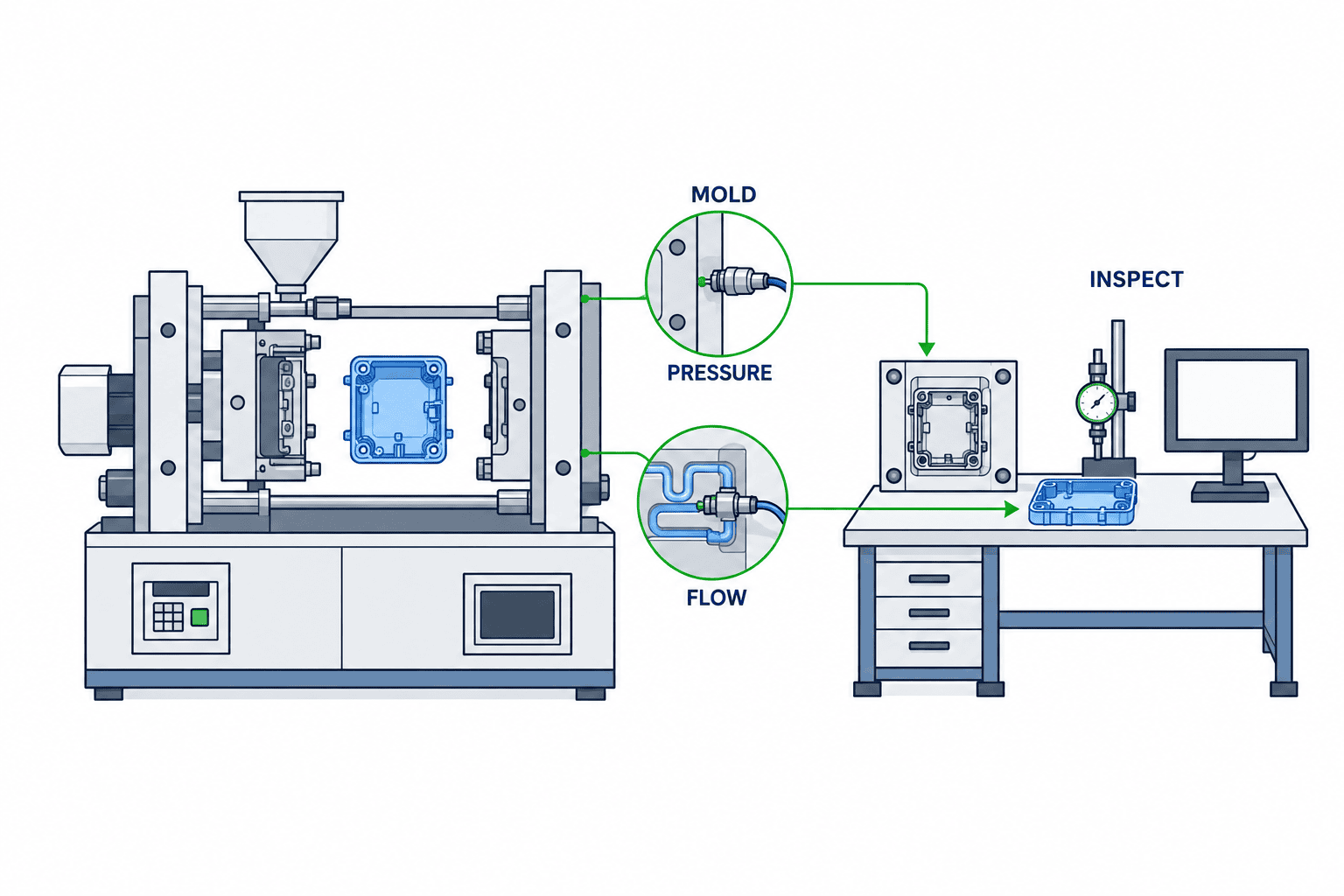
The ledger answers where a mold is, who owns it, how many cycles it has run, what was repaired and when an inspection is due. Condition monitoring asks whether its behavior has changed and why. Without a stable mold ID, sensor traces cannot be assigned reliably to a tool. Plants move molds between machines and put several molds on one press, so a model keyed only by machine can mix different histories. Each mounting period should link to the exact mold revision, machine, part and process recipe.
Shot count remains useful. It measures exposure, not wear itself. Resin formulation and reinforcement, temperature, water quality, lubrication, stock thickness, press settings, cleaning and prior repairs may all change how rapidly a component deteriorates. A conservative calendar or count rule may remain the right baseline after AI is installed. The project budget should separate ledger cleanup, signal acquisition, physical inspection, data integration, model development and the maintenance workflow. A license quote alone misses retrofitting, wiring, production stoppage, toolmaker approval and recurring support.
Define “end of life” for each component and failure mode
For an injection mold, end of life might mean the part no longer meets a drawing, the tool cannot run stably after reasonable repair, or continued use risks equipment damage. These are different labels. Flash may be associated with a worn parting surface, but clamping conditions or material behavior can also change it. A defect record must not automatically become a “mold wear” label. Cooling problems require distinguishing the mold channel from hoses, water supply and temperature-control equipment. Ejector problems need evidence from the return signal, movement time, marks on parts and a physical inspection.
For stamping, burr height, hole size, cut-edge condition and force traces can suggest punch or die deterioration. Material batch, strip thickness, feed position, lubrication and speed also affect the measurements. A Marposs BRANKAMP manufacturer brochure describes press-process monitoring, breakage detection and slower signal changes such as wear. It illustrates measurable signals; it does not guarantee a transferable remaining-life accuracy for any particular die. Keep immediate breakage protection separate from a planning recommendation for inspection or regrinding.
Choose one mold family and one decision for a pilot. A useful candidate has meaningful downtime or quality consequences, repeat runs, a reliable ID and inspectable history. A tool with many vague “mold repair” tickets but no component, cause or restart result may be a poor training source. Record normal production, setup, material changes, cleaning and confirmed non-mold causes as well as failures. Otherwise the model can learn that every process upset means the tool is worn.
Injection molding signals: what they can and cannot prove
Cavity pressure reflects filling and packing conditions and can be recorded within a mold. Kistler explains that sensor location depends on the quality characteristic: an end-of-fill problem and a transfer-to-holding-pressure decision call for different positions. An existing pressure trace should therefore be assessed for its specific monitoring purpose. Pressure drift alone does not uniquely identify mold degradation; resin, machine and settings can move the same trace.
Temperature also needs precise naming. Mold-surface temperature, cavity-adjacent temperature, coolant inlet and outlet temperatures and the temperature controller set point are different variables. A 2026 research paper investigated cavity-area temperature measurements for short-shot detection. This supports condition monitoring in its experimental setting. It is not evidence that the paper predicted the remaining life of a mold. For suspected cooling restriction, compare flow, temperature difference, cycle time, part warpage and physical checks of the water circuit and external equipment.
Other candidates include ejector return and timing, drive current, vibration, injection speed, clamp force, part dimensions and visual condition. Begin with signals that are safe to acquire, change before the targeted intervention and help distinguish alternative causes. If machining a sensor pocket into a customer-owned mold is not allowed, start with existing machine tags, external measurements and scheduled physical inspection. Tool design and warranty conditions must be checked before any modification.

Stamping signals require component-level history
A press can supply per-stroke force curves, peak load, strain measurements, feed position and cycle timing. Add measured burr, hole size or edge condition when these are relevant to the failure mode. A sudden force change may be useful for breakage detection; a gradual shift may prompt a wear inspection. Neither interpretation is reliable without context. A new coil, a regrind, a speed change or a repositioned sensor can move the curve without a newly damaged die.
Track total strokes, strokes since the last service and replacement dates for individual punches or inserts. Regrinding one punch does not reset the condition of every station. In a progressive die, preserve station identity and link the affected product features to the relevant component. A press-wide average can hide localized damage. The existing safety interlock and die-protection system must keep their own validated function; a predictive model should first inform planning and inspection.
Build a record that connects signals to the actual tool
The minimum useful key is mold ID × mounting period × production event. Keep mold revision, machine, part revision, material, recipe, shot or stroke number, sensor timestamp, inspection result and maintenance event. Note whether timestamps are in Thailand local time or UTC. For a tool moved between machines, close the old mounting period and open the new one. Map customer tool numbers to internal numbers, machine names to PLC tags and part numbers to drawing revisions. These are mundane steps, but they prevent a model from attaching one machine’s trace to the wrong mold.
A repair ticket should distinguish symptom, suspected component, physical finding, action, replacement part and restart decision. “Mold repair” alone is too ambiguous as a training label. Keep unconfirmed causes unconfirmed. Record cases where inspection found a resin, machine, feeder or sensor issue rather than tool wear. NIST’s work on maintenance-log data notes that insights depend on the quality of the original records. A better ticket design pays off in present-day root-cause work as well as future AI. See the manufacturing AI data-readiness guide for the wider data-integration groundwork.
Inspection photos need consistent component names, camera angle and scale; dimensions need the instrument and measurement location. A replacement insert should have its own history even if the mold body remains in service. Where a toolmaker outside the factory performs repair, agree which findings and measurements return to the factory record. Otherwise a predicted anomaly cannot be checked against physical evidence.
Test AI against three simple baselines
First, preserve the current shot-count or calendar rule. Second, establish a mold-specific normal range for pressure, temperature or force traces under known operating conditions. Third, use a decision table combining quality results with inspection history. AI should be compared against these baselines on useful warning time, missed deteriorations, unnecessary inspections and the ability to prepare a production stop. A higher abstract accuracy score is insufficient if a warning arrives after the maintenance window.
Split training and evaluation chronologically. Information entered after a repair must not appear in a prediction made before the repair. Distinguish a future period of a known mold from a genuinely new mold. Do not assume a threshold learned from one geometry, material or sensor position transfers to another. If confirmed end-of-life events are scarce, anomaly detection against a stable operating state may be more honest than a precise “shots remaining” estimate. An anomaly score is a prompt to investigate, not a diagnosis of wear.
NIST’s study of condition-monitoring-enabled maintenance emphasizes comparing algorithm measures with manufacturing performance under a maintenance policy. Apply that principle to the plant: measure whether alerts gave time to book a toolmaker, order a component or plan a changeover. Inspect a sample of tools that received no alert, or missed cases will remain invisible. When a flagged mold proves sound, determine whether the signal came from setup, material, sensor or cleaning before calling the alert false.
Design an actionable screen and a safe fallback
Show the mold and component, current recipe, changed signal, time of last valid data, reason for the alert, recommended check, owner and due point. The score may sit beside these facts. If data are missing, the sensor fails or the mold is outside the validated scope, say “prediction unavailable” and follow the established maintenance schedule. Route an alert to a specific work order or inspection; define who handles it on night shift and who signs off a return to production.
Start in shadow mode, with no automatic change to the machine or safety system. Capture operator responses and physical findings. Model and threshold changes need a version, reason, approver and rollback plan. After a material, machine, mold insert or sensor change, re-evaluate whether the original baseline still applies. Fewer alerts after a model update are not proof of improvement if product mix changed or missed failures increased.
Set an alert volume the team can actually handle
An alert queue that exceeds the number of cases maintenance can inspect in a shift is not operationally useful, even if its statistical score looks good. Prioritize by mold criticality, next scheduled run, availability of a spare mold, inspection time, suspected component and whether products may need containment. Append repeated observations for the same mold and event to one case instead of issuing a new case each cycle. Preserve the original force or pressure trace, part ID, material lot and mounting period as they existed when the alert was raised, so the decision can be reconstructed later.
The recipient of an alert may not be the person who performs every action. Quality may check the products, tooling maintenance may inspect the mold, and production planning may reserve a changeover. Put those roles, deadlines and handoffs into the notification. If night shift cannot open the tool, specify interim monitoring and what must be passed to the morning team. Record why an owner deferred an alert; that may reveal a workflow problem rather than a model-threshold problem.
Opening a mold and stopping production for inspection costs time. Focus the inspection plan on important failure modes, components that can be verified and windows when the line can be stopped. Continue sampling some molds that received no AI alert; without that check, missed deterioration will be invisible. Have maintenance and quality assess the same physical evidence and record their reasoning before changing a threshold.
Agree responsibilities with the mold maker
A loaned or customer-owned mold may produce useful machine data, but the factory may not have authority to dismantle it or add a sensor. Check the contract and drawing permissions first. Agree what condition evidence the external mold maker needs to make or confirm a repair decision, and whether photos, dimensional results and waveforms contain restricted information. Link the damage and corrective action found by the mold maker back to the factory’s production-event ID. That closed record is needed to evaluate the next prediction.
Pilot, FAT and SAT: ask for evidence at each step
Site assessment should gather drawings, the mold ledger, service tickets, machine tags, inspection plans and recent unplanned stops. Select one failure mode, reconstruct representative events and check ID linkage, clock alignment and label quality. If confirmed findings are missing, begin with measurement and records rather than a model promise. A pilot can first use existing tags, adding sensors only where their position and purpose are justified. Keep existing maintenance while the model runs in parallel.
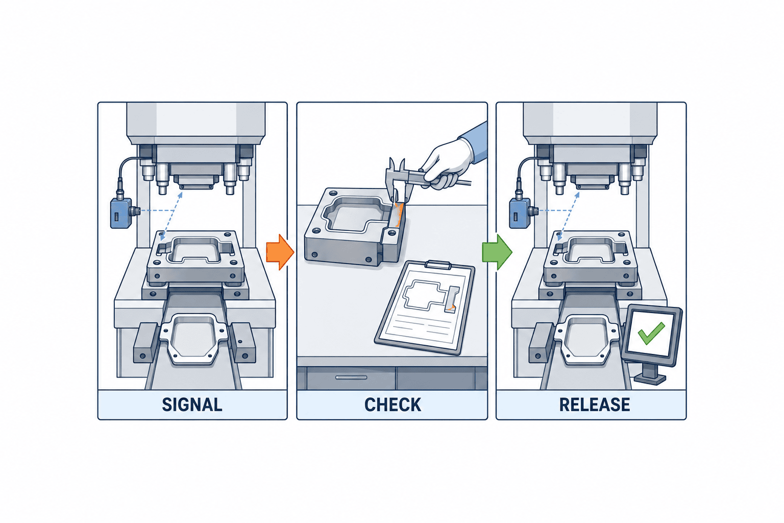
Factory acceptance testing should cover data ingestion, permissions, dashboards and exception displays. Site acceptance testing should reconcile real machine events to mold IDs and work orders, and demonstrate that alerts reach the right person. Include a known abnormal example, sensor disconnection, mold swap, material change, time error, network loss and the post-repair reset state. Agree beforehand what is acceptable for production use and when the system falls back to the original rule. Physical inspection remains the reference for a claimed mold condition.
Validate the lead time and the physical finding
A score that rises after a technician finds damage does not improve planning. Record when a warning could be issued, when it was read, when inspection became possible and when wear was physically confirmed. Useful lead time is the time in which a spare insert, toolmaker or planned stop can be arranged. Review false alerts, misses and inspection workload together. Continue scheduled checks of a sample of tools without alerts so that missed deterioration remains measurable.
Match the warning horizon to the planning cycle
A stroke-level breakage alarm and advice for next week’s maintenance window solve different problems. Define the decision date before choosing the horizon. Earlier warnings carry more uncertainty, so distinguish “monitor more closely,” “book an inspection” and “stop using the mold.” Do not connect an experimental AI score to a machine safety stop circuit.
Preserve the technician’s finding as a label
Record the symptom, suspected component, finding after disassembly, action, retest and final cause separately. “Mold repair” is too vague. If a defect was caused by material or machine setup, keep that negative example. When an insert or punch is replaced, retain the mold’s lifetime count while starting a separate count for that component.
Keep machine, material and tool changes distinguishable
Moving the same mold to another press, changing resin grade or resetting a temperature controller can move a signal without wear. Record equipment, material, sensor mounting, sharpening and mold revisions as events. Align units, sampling intervals and waveform start points before comparing runs. Keep a fixed evaluation set when updating the model; fewer alerts after a product-mix change do not prove improvement.
Common implementation mistakes
- Counting shots as deterioration: the count measures use, while condition needs inspection.
- Calling every defect mold wear: check material, setup, utilities and sensor faults.
- Erasing history after repair: track the body, insert and punch separately.
- Applying one score to every tool: show “prediction unavailable” outside the validated range.
- Choosing from accuracy alone: compare decisions, false alerts and misses with simple rules.
Ten questions for an RFP and quotation
- Which molding or stamping mold, component and failure mode are in scope?
- Is the output an anomaly, inspection advice, service timing or quantified remaining life? Who makes the final decision?
- How will mold ID, mounting period, machine logs, part inspection and repair tickets be joined?
- Which physical measurement confirms deterioration and who classifies ambiguous historical tickets?
- Which signals already exist, which sensors require tool modification and who approves it?
- What happens after a material change, regrind, insert replacement or machine transfer?
- How are shot-count rules and simple monitoring compared with AI, including missed cases and false alerts?
- What is shown during missing data, sensor failure or a mold outside the validated population?
- Where are tool drawings and production data stored, who can access them and how are they returned at contract end?
- What are FAT/SAT criteria, training, model maintenance, support and retest responsibilities?
Price the data join, sensor work, tool downtime, inspections and ongoing model operation separately. Estimate benefits against the chosen failure mode: unexpected stoppage, containment, over-inspection or late spare-tool preparation. Do not use a universal payback or accuracy percentage without the factory’s baseline. A clear “collect and validate records first” outcome can be a successful site assessment.
FAQ: what does an AI mold life prediction project need?
What data is needed for AI mold life prediction?
Start with mold and component IDs, mounting periods, shot or stroke counts, inspection dates, repair actions and physical findings. Add pressure, temperature, cooling flow, force curves and part inspection results only for the failure mode in scope. An unconfirmed cause in a repair ticket must remain uncertain rather than becoming a training label.
Can one model cover injection molds and stamping dies?
Their components, signals and service actions differ. ID management and alert workflow can be shared, while the prediction target and acceptance criteria should be validated by mold group and component. Test any transfer to an unseen tool or changed operating condition separately.
How should a Thai factory estimate return on investment?
Use its own history of unexpected stops, containment, emergency repairs and excess inspections. Include data joining, sensor installation, tool downtime, physical checks and support costs. Where failure events are scarce, update a range of estimates after the pilot rather than promising one payback period.
Practical next step for a Thai factory
Where headquarters owns the drawings, a Thai plant owns maintenance tickets and an outside toolmaker performs repairs, agree which findings may be shared and who closes the loop. Use consistent Thai and Japanese terminology for inspection, repair, replacement and release. Limit additional manual entry by collecting available machine and quality records automatically.
Start with a short list of repeatedly used molds, one component and one decision that currently causes trouble. Review the last unplanned stop, the physical finding and the signal history. Then compare the current count-based rule with a condition-based recommendation before expanding to more molds. TOMAS TECH can help connect the mold ledger with machine and quality data, scope the pilot and define acceptance criteria for maintenance. Prepare a mold list, recent service tickets, a sample equipment log and the production or quality problem, then contact TOMAS TECH.
References
- ISO 17359:2018 — General guidelines for condition monitoring
- Kistler — Cavity pressure
- Kistler — Injection molding sensor positioning
- Marposs BRANKAMP — Stamping Process Monitoring (manufacturer material)
- Kudo et al., International Journal of Automation Technology, 2026 (short-shot monitoring, not a mold-life validation)
- NIST — Assessment of condition-monitoring-enabled maintenance
- NIST — Hybrid Datafication of Maintenance Logs


