


Industrial UPS selection for a factory cannot start and end with the number of minutes printed in a catalogue. The advertised runtime depends on the connected load and battery conditions; two products with the same VA rating may support different watt loads. This guide is for the engineer or buyer protecting a PLC, industrial switch, HMI and industrial PC at a plant in Thailand. It walks through the protected boundary, factory UPS capacity calculation, PLC backup, OT network power, runtime requirements, procurement and FAT/SAT. Examples are illustrative, not performance guarantees for a particular product.
Start industrial UPS selection with the required behaviour after power loss
The entire production line does not necessarily have to keep making parts during an outage. There are three different objectives: ride through a brief voltage dip without rebooting controls; preserve records and move the machine into a defined safe state; or maintain control and supervision until a generator or another source takes over. Each objective calls for different loads and different time. The decision to power a motor is very different from a decision to keep only its controller alive. A 24 V DC control panel and an AC-powered industrial PC may need different arrangements.
Define the four stages of the target state after an outage
Write down the target state at each outage stage: detect, save, stop, and restart. Safety-related circuits require their own engineering and verification; installing a UPS alone does not establish that a machine is safe. Siemens describes its SITOP DC UPS as protecting 24 V power for controlled shutdown or continued operation. Rockwell Automation lists the safe shutdown of industrial PCs, PLCs and logging HMIs among industrial UPS applications. The purchase decision is therefore about the functions to keep alive, and for how long, rather than the biggest runtime number.
The power-hold requirement has at least two parts. One is the time for the PLC and IPC to record state and finish their shutdown sequence. The other is the uncertain period until utility power returns or the generator takes the load. Measure the sequence on the actual configuration, allow for the specified operating conditions, and compare candidates against manufacturer runtime data at the relevant load. For fiber segments in particular, check the supply at both endpoints. Our industrial media converter selection guide helps with the component-level power inputs.
Calculate factory UPS capacity using W, VA and peak current separately
For AC equipment, VA represents apparent power and W represents real power. Eaton’s sizing guide starts with each device’s voltage and current to obtain VA, and converts a watt-only rating using that device’s power factor. Do not assume a single power factor for every connected device. Check nameplates, manuals and measured operating data. A candidate AC UPS must satisfy both its VA rating and its watt rating. A 1500 VA label does not mean that 1500 W is available.
For a 24 V DC UPS, examine continuous and peak current, allowable output-voltage range, and the buffer time with the selected energy-storage module. The arithmetic 24 V × 10 A = 240 W is only a rating conversion, not a runtime calculation. Phoenix Contact lists a buffer period of 1.5 minutes at 10 A and 20 minutes at 2 A for its specific QUINT-DC-UPS/24DC/10 (2866226) product. That published product example illustrates why a generic promise that “a 24 V UPS lasts x minutes” is unsound.
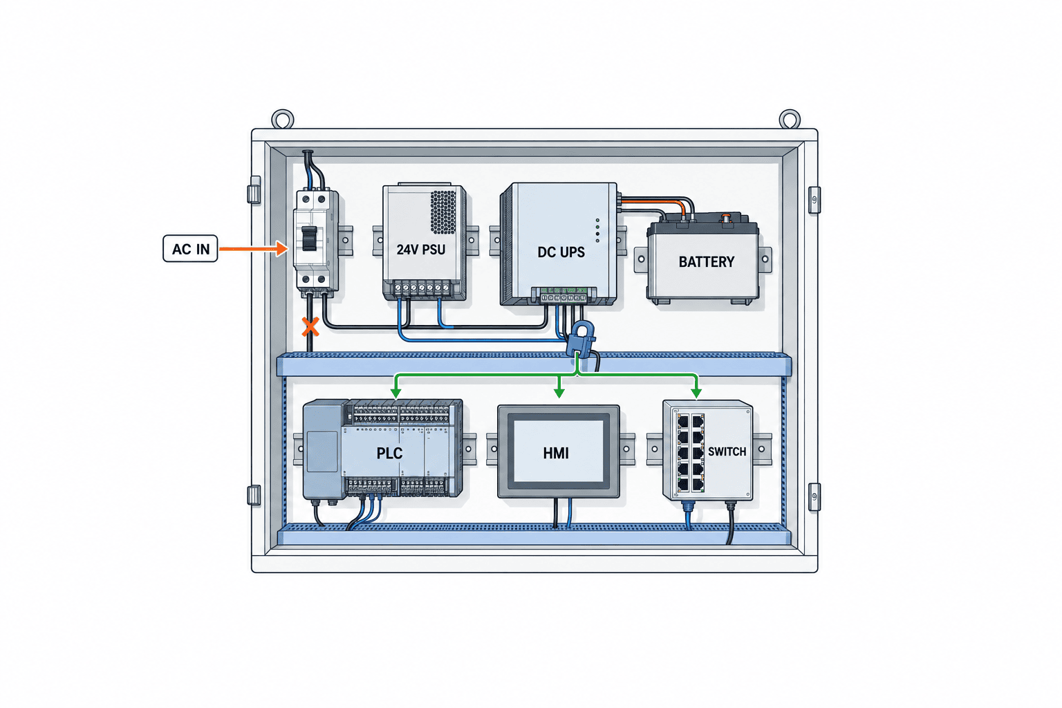
Build a practical load register
Build a load register before asking suppliers for a model number:
| Item | Record | Why it matters |
|---|---|---|
| Protected load | PLC CPU and I/O, HMI, IPC, switch, gateway and other necessary devices | Defines which functions survive |
| Supply | AC, 24 V DC and panel location | Defines UPS and wiring boundaries |
| Normal load | Nameplate and measured W, VA or A | Determines running capacity and runtime |
| Peak load | Startup, PoE, charging and switching conditions | Prevents an overload trip |
| Stop order | Alert, save, output shutdown and OS shutdown | Defines the actual hold time |
| Test evidence | Event log, PLC state, machine state and transfer result | Makes FAT/SAT measurable |
The bill of materials for one panel is rarely sufficient. A PLC may remain powered while its upstream switch or gateway loses supply. An HMI can remain on while communication to the PLC has disappeared. Trace the required path from the machine to its recorder or operator station. Mark every power source along that path and distinguish loads that must remain from those that can shut down. This drawing is more useful than a generic list of “critical devices.”
A worked capacity example, not a plant measurement
Suppose a hypothetical 24 V control system uses 3 A for the PLC branch, 2 A for an HMI, 1 A for a switch and 1 A for a gateway. The normal total is 7 A. If a future module adds 2 A, the planning load becomes 9 A. This arithmetic does not mean that a 10 A DC UPS is automatically suitable. Check switch startup current, charger current, short overload capability, temperature derating and the selected device’s buffer-time table at 9 A. Verify the target time with the chosen battery module.
For a separate hypothetical AC branch, imagine an IPC at 180 W, a monitor at 50 W and a router at 20 W: 250 W in normal operation. Obtain their VA or power factors, capture startup peaks, and compare with both W and VA limits of the proposed UPS. Eaton recommends at least 15% VA headroom in its general sizing guide; a Schneider Electric FAQ gives an example of using about 80% of the available rating. These are vendor guidance and examples, not a universal industrial standard. The project’s margin needs to reflect actual loads, expected additions, ambient temperature and redundancy.
Battery capacity is not the same as runtime
An Ah label and a simple “voltage × Ah ÷ load” calculation omit discharge rate, conversion loss, voltage cut-off, temperature, ageing and product protection logic. Use rough energy arithmetic only to shortlist configurations. Specify accepted runtime by reference to the manufacturer’s load-specific table under stated conditions, then measure it in the acceptance test. Those Phoenix Contact figures (1.5 minutes at 10 A and 20 minutes at 2 A) apply only to the named QUINT-DC-UPS/24DC/10 product under the manufacturer’s stated conditions; they are not a guaranteed runtime for other 24 V UPS models.
Output capacity and storage capacity are also different. Eaton explains that adding external batteries may extend runtime without increasing the UPS’s output power rating. A battery pack does not fix an overloaded inverter. Conversely, a unit with adequate output capacity might still need more storage or generator integration to finish the required sequence. Request a runtime statement that always names the load, not a bare number of minutes.
PLC UPS backup requires a defined control-power and shutdown boundary
Keeping the PLC CPU alive is not always enough. If input sensors, remote I/O or the communication switch disappear first, the controller may see an incomplete plant state. Decide which components remain energized together and which outputs must drop on an outage. Retained PLC memory is also not proof that the industrial PC closed its files or that the last production record reached storage. These are separate test outcomes.
A 24 V DC UPS can be fitted close to control-panel loads. Siemens documents SITOP options for diagnosis and control through industrial communication, including PROFINET and OPC UA on relevant products. Capacitor buffers address short dips; battery-based UPS arrangements can support longer holding periods. Phoenix Contact describes capacitor buffer modules for interruptions measured in seconds. A brief dip may not justify a battery arrangement, while a controlled IPC shutdown may exceed what a short buffer can support. Match the energy store to the measured requirement.
Divide protection into three power domains
Divide the loads into three power domains. The control domain contains the PLC, indispensable I/O and the minimum control network. The operation and recording domain contains selected HMIs, IPCs, historians and gateways that are needed until the stop completes. The drive and auxiliary domain contains motors, heaters, valves, lighting and similar high loads. Connecting every drive to a small UPS can sharply reduce the time available to the control system. For anything left unpowered, specify its safe outage state separately.
Map dependencies between domains. Does the IPC need the switch until its shutdown is complete? Does the PLC need a confirmation signal? Is the HMI used for an essential operator action or only to display an alarm? Add explicit outage and return-of-power state transitions to the control specification.
UPS signals need an actual response in the PLC and IPC
Decide where the mains-failure, battery-operation, low-battery, fault and replacement signals go. Depending on the model, these may be relay contacts, USB or an industrial network interface. A Siemens SITOP UPS1600 manual, for example, documents buffer enable, transfer threshold, buffer duration and additional time after PC shutdown. The presence of a signal does not itself implement a safe stop. The PLC program and IPC configuration must receive it and execute the defined order.
Log the outage event with a common time reference. Capture the UPS input and battery state, load, PLC mode, IPC shutdown start and completion, return of power and permission to restart. This lets SAT prove that the sequence finished within the allotted time. Test a brief recovery followed by another dip, recurring sags and a second outage before the battery has fully recharged. A clean single outage is only one of the relevant plant scenarios.
Power the whole required OT network path
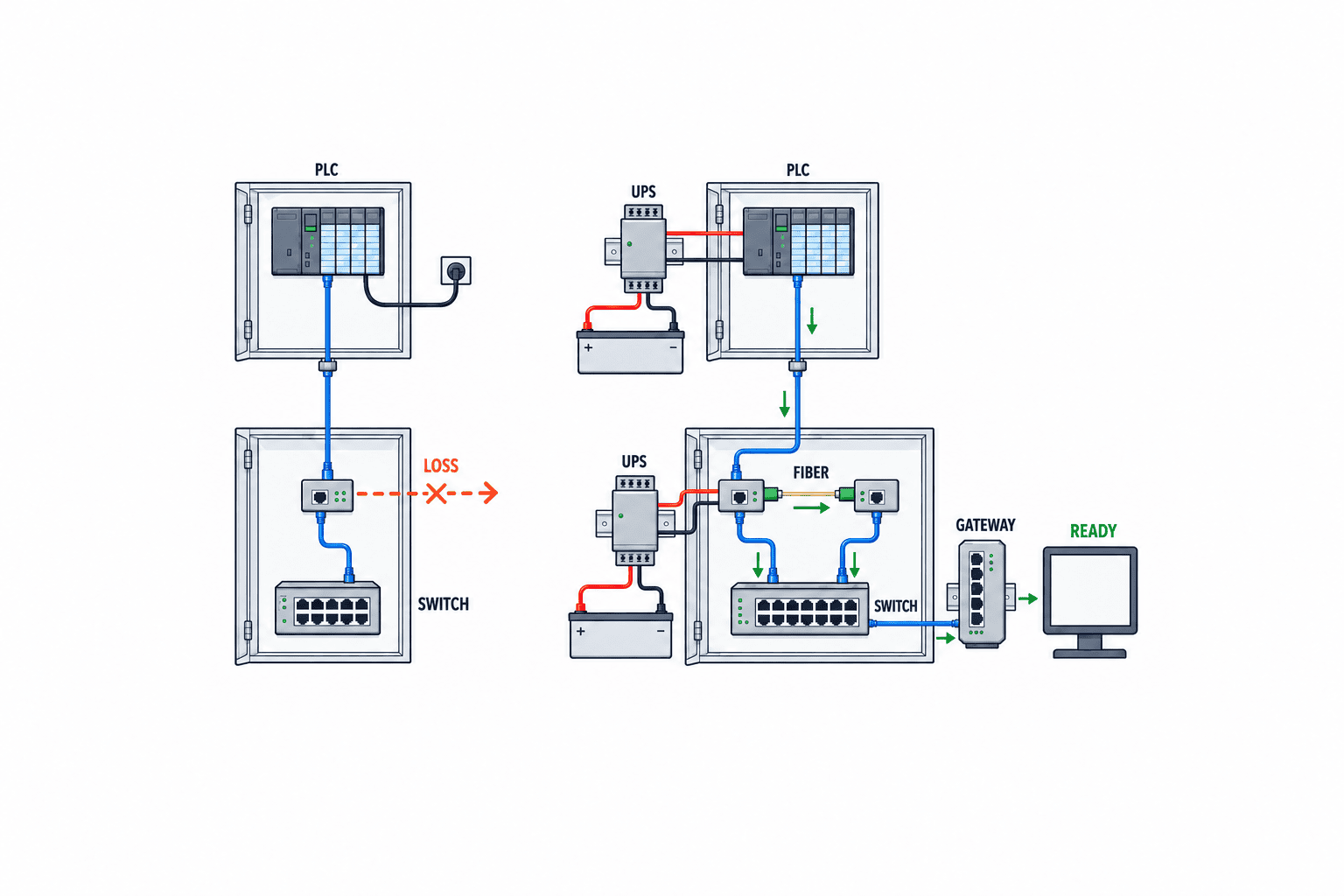
“The switch has a UPS” says little if a media converter, optical termination, gateway, access point or firewall on the path loses supply. Draw the route from the PLC to its historian or supervisory endpoint and record the supply and location of each active device. Separate traffic needed to complete control shutdown from traffic that merely needs to store records. This reduces the temptation to keep an entire office network running to save one PLC log.
A UPS does not replace OT/IT segmentation or network security. If the boundary firewall is retained, assess what happens when its management switch or upstream circuit fails. If cloud access is lost, local buffering depends on the gateway or application design; electric power alone does not prevent data gaps. Observe power, communications and data recording in the same outage test. Our industrial media converter selection guide covers one network component; this article specifies its electrical dependency.
For PoE switches, include powered cameras and access points in the maximum load, not just the switch chassis. Nonessential cameras can consume capacity reserved for the PLC communication path. Consider separate supply segments or a defined shutdown priority. A redundant switch ring will not survive a power loss if both nodes depend on the same unprotected source.
Turn UPS runtime into measurable FAT and SAT requirements
“Ten minutes of backup” is not an acceptance criterion until it states the connected load, measurement start event, ambient conditions, battery state and the device that must remain alive last. Ask vendors for load-specific manufacturer runtime data under normal, peak and future loads. Choose the conditions to be witnessed at acceptance. Avoid carrying a general catalogue figure into the purchase order without those conditions.
Passing an outage test means more than observing that indicator lights stayed on. The PLC must reach the specified state, hazardous outputs must not remain energized, the IPC must finish writing, necessary records must survive, and restoration must not cause an unexpected automatic start. Controls, maintenance and production owners should agree on those outcomes. Machinery-safety compliance needs its own applicable assessment.
What to verify at FAT
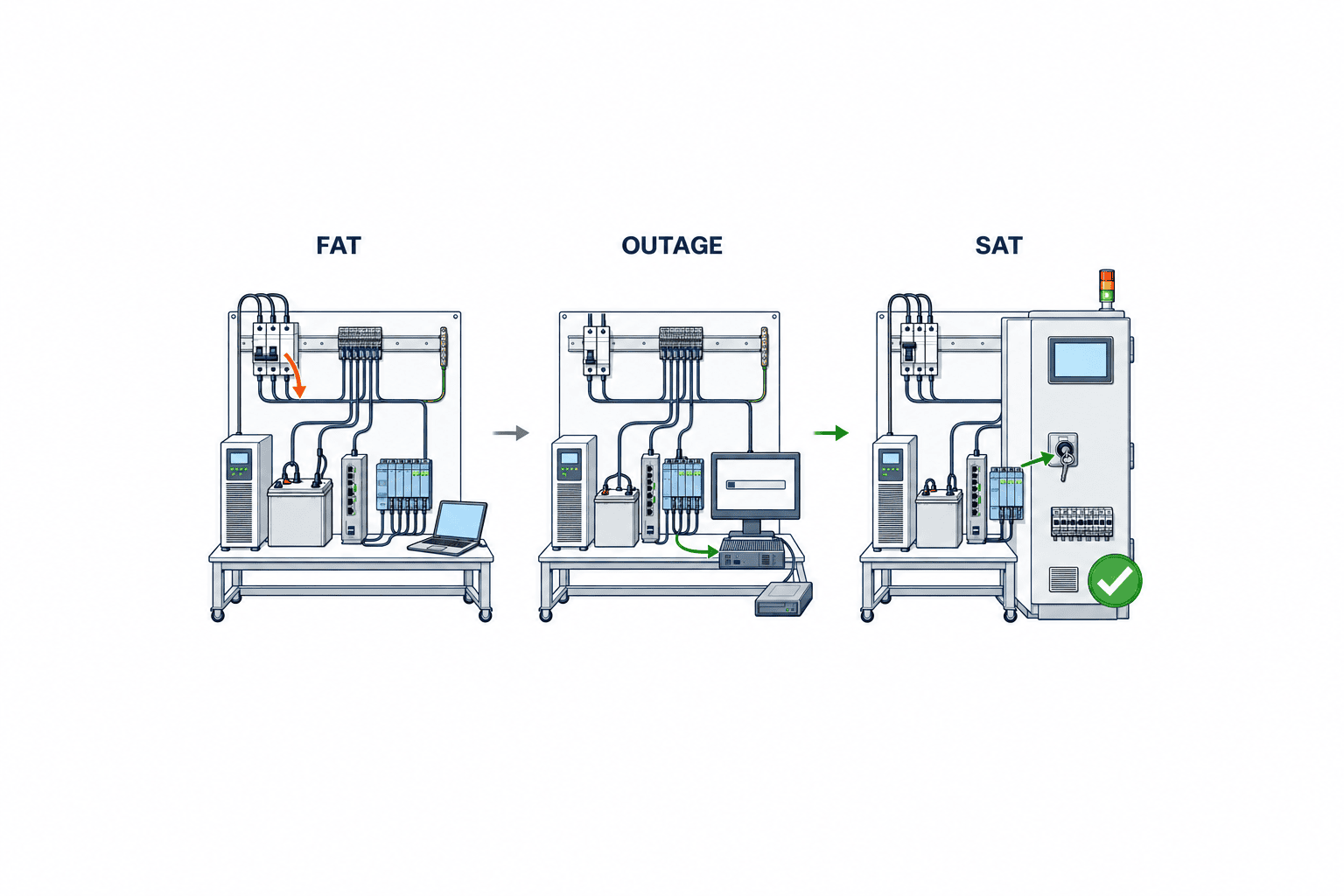
At FAT, use the proposed UPS and representative loads to measure transfer and holding time. Where possible, connect the PLC, IPC, switch and gateway with production-like settings. Test a dip, a sustained outage, restoration and another outage before full recharge as separate cases. Merely simulating a software “power lost” bit does not verify that the real supply holds the load. Record W or A, ambient temperature, UPS settings, battery condition, input cut-off time, alarm time, PLC state and the time each load shuts down.
For illustration only, a hypothetical specification might demand that the IPC save and shut down within 90 seconds while the PLC and switch remain powered for 120 seconds. These figures are not manufacturer default values or recommended limits. A project’s actual values must come from its process and measured stop sequence.
What to verify at SAT
At SAT, repeat the critical sequence using the installed panel, protection devices, cabling and live communication path. Actual PoE and startup loads may differ from the FAT bench. Under the site’s approved safe test procedure, interrupt the input and record the machine and event log. Verify restoration as carefully as shutdown: simultaneous startup can overload a source, clocks and states can diverge, and an unfinished lot may be handled twice. Specify startup order, recharge checks, alarm clearance and the person authorized to restart production. Preserve failures, changes and retests in the SAT record.
Turn the hold-time calculation into an operating sequence
Determine the hold-time budget from a timeline, not an arbitrary sum. Include detection, PLC state transitions, IPC and HMI saving, the last moment network devices are needed, and any generator transfer uncertainty. Parallel tasks should be measured as parallel; dependent tasks belong on the critical path. Add a justified allowance for age and planned growth, then compare the result with the chosen model’s load and environment data.
Choosing AC UPS, 24 V DC UPS or a capacitor buffer
An AC UPS is a candidate when IPCs, servers, AC HMIs or a network rack need a common supply. Check input and output voltage and phases, both W and VA ratings, output waveform, service bypass, communication alerts and battery replacement. A large AC UPS upstream does not by itself validate downstream AC/DC supplies, branch protection or the shutdown signal path.
A 24 V DC UPS sits close to PLCs and DC industrial switches. Compare continuous and peak current, output voltage range, the specific storage module, diagnostics and wiring. Siemens and Phoenix Contact publish 24 V options with status signalling, but interfaces and compatible batteries differ across models. A family name is not an engineering specification.
A capacitor buffer primarily bridges short voltage disturbances. Phoenix Contact describes QUINT BUFFER for failures lasting seconds, while PULS lists typical hold times in milliseconds for certain capacitor-buffer models. A battery-based DC UPS is a candidate for longer hold times but brings charging, replacement, temperature and ageing requirements. Use the plant’s outage log to distinguish frequent short dips from longer losses requiring an orderly stop.
Compare maintenance as well as purchase cost
The commissioning plan must cover battery inspection and replacement, spares, alarm monitoring, recharge time and periodic outage tests. Eaton cites battery degradation as one reason for headroom; headroom does not eliminate maintenance. Check the maker’s ambient-temperature and lifetime conditions if the battery will live inside a warm panel. Ask whether the supplier provides a replace signal, central status, event history, and a way to maintain the unit without an unplanned shutdown. A low unit price can be outweighed by repeated panel work and retesting across a multi-site rollout.
What the RFQ should ask suppliers to return
Supply a single-line diagram, protected-load register, normal/peak/future loads, required shutdown sequence, ambient conditions and installation constraints. Ask each bidder for the proposed W/VA or DC-current ratings, storage configuration, manufacturer load-based runtime evidence, transfer and notification scheme, service and bypass arrangement, warranty and replacement parts. Put these in the same comparison table. A list of model numbers alone does not show whether the plant’s target state will be achieved.
Define responsibility for UPS sizing and wiring, PLC outage logic, IPC shutdown, OT network power, FAT/SAT and operator training. The UPS supplier, panel builder, system integrator and plant maintenance group may each own only one part. Without an agreed boundary, all devices can pass individually while the line-level restart procedure remains undefined. Include backup and rollback when existing PLC code changes.
An RFQ clause that allows fair comparison
An RFQ clause can read: “Identify the PLC, required I/O, industrial switches, gateways and IPCs in a protected-load and power-source schedule. Following mains failure, the IPC shall preserve records and shut down within its specified time; the PLC shall enter its defined safe state, and the communication path shall remain powered until control shutdown finishes. For normal, peak and future loads, state rated W/VA or DC current, storage configuration, runtime supported by manufacturer data, environmental limits and charging conditions. FAT and SAT shall record equipment state and event logs through loss, dip, restoration and a second outage.” Fill the time values from the real line, not from this example.
Separate the commercial price for the UPS, batteries, panel work, cabling, shutdown logic, communications, tests, training, spare parts and replacement labour. Estimate downtime cost from the plant’s own incident history and production plan, not another company’s claimed percentage reduction. Compare one central UPS with several smaller power domains in terms of failure scope, maintenance access and recovery sequence.
Power-boundary issues often overlooked at factories in Thailand
New lines and lines expanded over many years do not have the same quality of electrical documentation. When the drawing differs from the installed panel, a PLC supply believed to be UPS protected may actually use another branch, or a recently added switch may draw from an unprotected outlet. Before procurement, reconcile the drawing with actual cables, breakers, AC/DC supplies and power sources for each active network device. For older panels, keep photographs, model numbers, circuit numbers and measured loads together.
Suppose a PLC determines how a machine stops while an IPC in another cabinet saves the production record. Updating only the PLC cabinet’s UPS will not preserve the last lot if the IPC fails first. Backing up only the IPC is also insufficient if the switch carrying PLC state goes down. Production, quality and maintenance teams should agree on which data must survive and return every required communication device to the load register. This cross-functional review can improve the design before another UPS is purchased.
For factory wireless links, check the PoE switch and controller as well as the access point. A wireless terminal can retain its own battery and still lose communication when the access point loses power. Yet every access point in a building need not be backed up. Identify the zones whose communication is needed during shutdown. Our factory Wi-Fi site survey guide addresses coverage and placement; the UPS decision adds their power dependencies.
Do not treat a brief dip and a long outage as one test
Disturbances include a voltage dip, a full loss, unstable restoration, and recurring intermittent losses. If the problem is a dip, first record which supply falls and how far. An UPS may hold the output while an upstream protective device or downstream supply responds differently. Test both the short event and the return to normal so that the system does not remain on battery unnecessarily. A long-discharge test alone cannot show this behaviour.
A second outage has different initial conditions. If storage has not recovered its charge, the first measured runtime may not be available again. Check the manufacturer’s recharge conditions and test another failure at an interval that matters to operations. Release the line for restart after confirming UPS readiness and reconciling the interrupted machine and lot state, not just after seeing mains voltage return.
Include the local environment. If the interior of a control cabinet in a Thai factory is warm, an air-conditioned office test condition may not describe its operation. Check the product’s permitted ambient range, storage placement, ventilation and service access. Measuring load and cabinet temperature with the door closed, near heat sources and during a hot shift gives a sounder operating case. A quote promising a number of minutes without temperature and load conditions invites a dispute at acceptance.
Draw every network power point
For a fiber link between cabinets, examine both ends. Protecting the PLC cabinet alone will not preserve communications if the far-end media converter fails. Compare the converter’s power input, redundant-power options and ambient rating, then decide whether both endpoints must remain online. Our industrial media converter selection guide covers product comparison; the electrical continuity question belongs in the UPS design.
A logical network diagram can hide a shared electrical failure point. Two switches may provide separate paths but depend on the same AC distribution board, the same DC supply or the same UPS. If power independence is required, identify that common point explicitly. Full duplication also increases cost and maintenance, so state which failure the redundancy is meant to absorb and focus on the line with the greatest stop consequence.
Application behaviour matters after communications fail. If a historian link is unavailable, can the gateway store timestamped data locally and resend it without duplicates? If a PLC clock changes after an outage, how will event records be reconciled? When the objective is to avoid data loss, test connection loss and recovery alongside power hold time. Add local buffer capacity and full-buffer behaviour to the specification if they are material.
Eight questions to answer before narrowing the model list
First, which exact loads must remain alive: PLC, I/O, communications and IPC? Second, which device needs power last in the shutdown sequence? Third, what evidence proves a normal stop rather than simply a dark screen? Fourth, have both running and startup loads been measured? Fifth, do competing suppliers report capacity and runtime under the same load and environmental conditions? Sixth, are external storage and UPS output rating correctly treated as separate quantities? Seventh, who receives the outage signal and what is the exact response order? Eighth, what happens during maintenance and a second outage before recharge?
Once these questions have been answered across departments, the candidate types and load range become much clearer. If the model is selected while the register is incomplete, a later panel change or switch addition can invalidate the original runtime data. Purchasing should compare the same load and acceptance conditions across bids before comparing the unit prices.
Continue monitoring after the acceptance test
One successful outage test on handover day does not guarantee the same runtime after loads are added, batteries age or cabinet temperature changes. Track changes to protected devices, running and peak loads, storage readiness, alarms, outages and battery replacements. For critical lines, schedule controlled outage tests and check both safe machine state and retained data. Set the test interval from the maker’s instructions, equipment criticality and planned maintenance windows, rather than applying an arbitrary period everywhere.
Add UPS impact to change control. An extra PoE camera increases switch load, but the UPS calculation will not be updated if only the IT team knows of the change. Equipment-change forms can ask whether protected load, stop order or runtime evidence must be revised. Reviewing event logs after outages can expose unexpectedly early low-battery alarms or a communication path that disappeared before the PLC did.
For multi-site rollout, standardize the load register, shutdown timeline, FAT/SAT evidence and maintenance procedure first. Do not copy one model’s capacity blindly to every plant. Cabinet temperature, outage pattern, network architecture and allowable stopping time vary. Standardize the decision process and proof format; select each site’s final configuration from local measurements.
The deliverables to be retained after inspection are not limited to equipment operation manuals. It is essential to manage information such as the criteria used to select each piece of equipment and the assumed backup duration, who measured the load ledger and when, who approved the shutdown sequence during power outages, and which alarms should be checked during battery replacement. If outdated tables are used after modifications such as changes to distribution panels or replacement of communication devices, there is a risk of misjudging capacity. Attach revision numbers and modification dates to drawings, actual load measurement sheets, backup time data for each product, and FAT/SAT records, and ensure that all materials can be traced from the equipment number.
In factories where power outages may occur at night, it is necessary to have procedures that allow on-site personnel to respond even in the absence of designers. For operators, provide concise instructions on whether to continue or stop production when an alarm is triggered, how to handle work-in-progress, and which indicators and records to check before restarting. For maintenance staff, prepare diagnostic procedures to check the status of the input power supply, UPS, battery modules, and downstream equipment in sequence. Clearly specify the person responsible for authorizing restart to prevent the misconception that power restoration alone means it is safe to resume operations. With such handover documentation, it becomes easier to reproduce the behaviors demonstrated during blackout tests in actual operations.
Frequently asked questions
Is the VA number enough for factory UPS capacity calculation?
No. For AC equipment check both W and VA, measured running load and startup peaks. For DC equipment check continuous and peak current and voltage range. In both cases compare the required hold time with the exact model and storage configuration’s load-specific data.
Does backing up the PLC preserve the OT network?
Not automatically. Trace every switch, media converter, router and gateway between the PLC and the system that needs its data. The required path must remain powered until the final control or recording action is complete.
Can the displayed UPS runtime become the shutdown requirement?
No. A displayed estimate or catalogue figure applies to conditions and a load. Specify the real load, temperature, battery state and configuration; then verify the stop sequence and actual hold time at FAT and SAT.
Is a battery UPS necessary for every brief dip?
No. A capacitor buffer may suit short disturbances, while controlled IPC shutdown or generator transfer may require a longer battery arrangement. Check the maker’s curve at the load current in question.
Why perform both FAT and SAT?
FAT examines the proposed transfer, signals and timing before installation. SAT checks the actual plant wiring, load and operating procedure. Define scope, pass criteria and safe methods in the purchase specification.
Conclusion
Industrial UPS selection begins with the functions and shutdown order needed after power loss. Register every PLC, IPC and OT network power dependency; compare AC loads with both W and VA, and DC loads with current and voltage limits. Prove runtime at the selected load and storage configuration using the manufacturer’s data and an outage test. An RFQ with those conditions, followed by FAT and SAT for loss and restoration, tests continuity at line level rather than at a single box.
If you are still mapping the control-panel and OT network power boundary, contact TOMAS TECH. We can help turn the load register, shutdown sequence, candidate comparison and FAT/SAT evidence into one reviewable specification.
References
- Eaton, UPS sizing guide
- Eaton, UPS buying guide for network closets
- Schneider Electric, Things to consider in sizing a UPS and load
- Schneider Electric, UPS buying guide
- Siemens, SITOP DC UPS modules
- Siemens, SITOP UPS1600/UPS1100 manual
- Phoenix Contact, QUINT-DC-UPS/24DC/10
- Phoenix Contact, Buffer modules
- Rockwell Automation, Uninterruptible power supplies documentation


