


Selecting an industrial network TAP starts with the production link, not a product catalogue. A TAP can support passive visibility of PLC, HMI and plant-system traffic, yet a poor choice can interrupt the line during installation, omit one direction, overflow a monitor port, or behave unexpectedly when power fails. This guide helps a Thailand factory team compare TAP and SPAN, specify copper and fiber links, and turn the result into an RFP and FAT/SAT acceptance plan. It addresses the acquisition of traffic evidence; switch features, firewall policy and network redundancy have separate design decisions.
Define the observation link before selecting an industrial network TAP
A test access point is inserted into a communication link and supplies a copy to a monitoring device. The name does not guarantee that every packet will be visible. Media, speed, direction, aggregation, monitor-port capacity and failure behavior vary by model. Mark candidate links on the current network drawing: PLC to industrial switch, cell switch to distribution switch, or production cell to plant backbone. Note the endpoint tags, normal route and any alternate route after a topology change.
Separate the purpose of observation. Asset discovery needs enough protocol conversation over time to identify devices. Troubleshooting needs evidence from bursts, retransmissions and error periods. An intrusion detection system (IDS) needs the directions, timestamps and retention appropriate to its rules. A traceability investigation may need PLC events aligned with MES transactions. One observation point rarely covers every purpose. List the source and destination of each required conversation and trace its path in normal and failover conditions. A TAP at a cell exit cannot see a PLC to HMI exchange that remains inside that cell.
NIST SP 800-82 Rev. 3 Final frames OT security around performance, reliability and safety. As of October 2026, Revision 4 is an initial public draft, so Revision 3 is the current final revision. This practical selection procedure does not mean NIST endorses a particular TAP. It applies those OT constraints when deciding where and how to observe a running process.
Build a monitored-link register
For every candidate, record endpoint tags and drawing revision, connector and media, negotiated speed, VLANs, PoE, protocols, alternative paths and the available maintenance window. An interface specified or configured for 1 Gbps may currently negotiate at 100 Mbps; conversely, an old drawing may say 100 Mbps although the live link was upgraded to 1 Gbps. Check the live port and cabling rather than ordering from a diagram alone. Include the traffic that will remain invisible from this point. A ring can redirect traffic after failover. If the desired flow no longer crosses the observed link, missing data is a design issue, not a TAP malfunction.
TAP versus SPAN: compare acceptance evidence
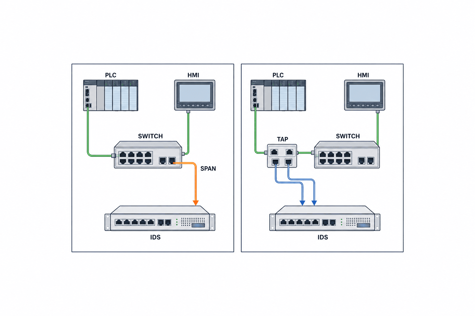
SPAN copies traffic chosen by a switch to a destination port. On a compatible switch with a spare port it may avoid cutting the physical link, although a configuration change still needs approval. An inline TAP requires a planned disconnection and insertion. Both methods require proof that the desired packets reach the sensor under the actual load and configuration.
Cisco’s IE3x00 SPAN/RSPAN guide describes source and destination ports and platform restrictions. Its Nexus 9000 SPAN guide shows why restrictions are product-specific; do not apply a data-center switch limit to an IE switch. Verify the exact model, software version, source count, direction, filters and destination port used in the plant.
| Question | SPAN | Inline TAP |
|---|---|---|
| Intervention | Switch configuration and change approval | Physical insertion, outage window and rollback |
| Copy behavior | Depends on switch feature, load and port settings | Depends on media, TAP mode, monitor ports and power |
| Failure domain | Monitoring shares the production switch | Adds connectors and a device to the production link |
| Direction | Confirm what RX and TX mean on the chosen source | Confirm separate breakout or combined output |
| Useful starting case | Existing switch can meet the measured need without an outage | Dedicated observation point and specified failure behavior are required |
Do not assume all TAPs are lossless or all SPAN sessions drop critical traffic. SPAN may meet a measured requirement. TAP aggregation can oversubscribe its output, fiber splitting can exhaust an optical budget, and installation itself carries risk. Subject both options to the same peak-traffic and failure tests.
Describe direction by communicating devices
RX on switch A is traffic sent by B; that same packet is TX at the other end. Write “PLC request to HMI” and “HMI response to PLC” in the test plan rather than relying on a port label. A breakout TAP offers A-to-B and B-to-A on separate monitor outputs, requiring two sensor inputs. Aggregation combines them; then the sum must fit the monitor interface and the sensor. Document whether tags, errors or timing information are preserved by the selected model.
Size monitor ports for both directions and packet rate
A full-duplex 1 Gbps link can, in principle, carry close to 1 Gbps in each direction simultaneously. Combining both directions into one 1 Gbps monitor output can exceed its capacity. This is a capacity boundary, not a prediction that every plant link continuously carries 2 Gbps. Measure normal shifts, changeovers, startup, shutdown, batch MES transfers and failover. Keep the measurement interval and method with the results; a single average conceals short bursts.
Compare both bit rate and packets per second against monitor-port and sensor capacity. Small frames can stress packet processing even when Mbps appears comfortable. Include NIC-ring drops, interface drops, capture drops, timestamp accuracy and storage throughput in acceptance. If one output is insufficient, consider breakout ports, a suitable packet broker, a faster output or an additional sensor. A packet copied to the port but dropped by the sensor is not usable evidence.
Decide whether the project stores full packets, metadata or alerts. Each has a different retention and privacy burden. A TAP cannot reveal encrypted payloads by itself; document what can be learned from metadata and approved logs. Any decryption proposal requires its own authorization and operational review.
Prove copy quality with known traffic
Send a known sequence in both directions in an isolated test or approved outage window. Compare counters and timestamps at the sender, far endpoint and monitor output. Application success alone does not prove that the copy contains every expected packet. Record filters, sampling, clock offset, flow identifiers and accepted loss thresholds. Do not inject test load into a running production control network without production authorization.
Choose copper or fiber from physical conditions
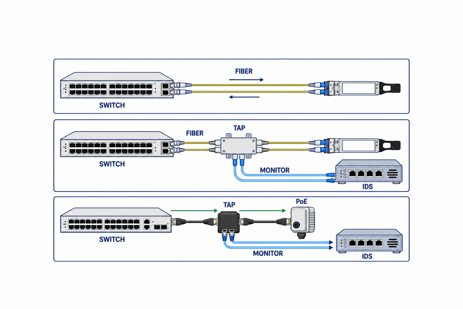
For an RJ45 copper TAP, check supported speeds, auto negotiation, MDI/MDIX behavior, cable length, shield and grounding, site noise and whether it passes the required PoE mode and class. “Passive” in a brochure does not establish what a gigabit copper device or its copy electronics will do without power. Request the exact wiring and power-loss specification.
For fiber, match single or multimode fiber, wavelength, connector, polarity, both transceivers and insertion loss. A 50/50 or 70/30 split expresses optical allocation; more light to the monitor side can leave less budget for the production receiver. Obtain live optical power readings, transceiver limits and the vendor’s loss at the actual wavelength, then calculate and verify margin on site. A media-conversion TAP adds a powered component and its own latency and failure modes. Keysight’s media-converter TAP page illustrates a category, while current model fitness needs a current datasheet and test.
PoE is a separate check. Identify the power sourcing equipment and powered device, PoE standard and class, pass-through capability and what happens during renegotiation. Inserting an incompatible Ethernet device can interrupt power to a field terminal. Also draw the monitoring sensor’s own power supply; passing PoE on the production link does not mean the monitor port powers the sensor.
| Site condition | Evidence requested in procurement | SAT observation |
|---|---|---|
| Copper and PoE | Speed, PoE class, power-loss pass-through | Power return, link renegotiation, device recovery |
| Fiber | Wavelength, fiber type, split ratio and loss | Received optical power, errors and spare margin |
| Monitor output | Breakout or aggregation, speed and direction | Both-way peak, drops and sensor capture |
| Cabinet | Temperature, vibration, space and mounting | Cable bend, access, temperature and indicators |
Specify which side gets the optical split
The number “70/30” is insufficient unless the drawing states which share reaches production and which reaches monitoring. Require a port and polarity drawing, insertion-loss data at the operating wavelength and connector-loss allowance. If the existing receiver is already close to its sensitivity limit, repair or redesign the link before adding the observation point. Visibility should not consume the margin needed for control availability.
Test power and link failures by exact model
Some copper TAPs have a fail-safe relay connecting production ports when power is lost. Garland Technology’s copper fail-safe description explains that behavior for its applicable products. Its model-specific transition claims cannot be generalized to every TAP. A connected path also does not prove uninterrupted PLC sessions: link renegotiation, controller timeouts and alarms may still occur. Test the selected model with the actual controllers and switches.
A passive optical splitter may need no power for the production optical path, while a monitor converter and IDS still need power. Distinguish TAP power loss, one-sided power loss, monitor cable removal, production cable removal and internal failure. Note whether a link failure propagation (LFP) feature is present and wanted. The Garland data-diode TAP catalogue lists different modes and functions by model. Propagating a failed link may help one failover design and disrupt another. State model, firmware, settings and expected link behavior in the RFP.
Passive monitoring and a data diode are different requirements
Passive monitoring is an operating practice: the observer does not scan or issue control commands into the production network. A normal Ethernet monitor interface is not necessarily physically incapable of transmission. If hardware-enforced one-way flow is required, specify and test a data-diode TAP or equivalent architecture. Garland describes a product intended to move the observed copy one way; evaluate the complete system, including management ports and other routes, before treating a device claim as a system guarantee.
The IDS comes after the TAP
A TAP supplies copied traffic. An industrial IDS interprets it to produce asset information and possible alerts. Adding a TAP alone will not generate threat findings. An IDS cannot recover a conversation that never crossed the observation point, was copied in only one direction, or was discarded by the sensor. Accept capture quality, analytic coverage and alert response separately.
Specify supported protocols and versions, encrypted-traffic limits, retention, false-positive review, update process and data location. Keep the management network distinct from the monitor input. The sensor may have management access even when the TAP output is intended as receive only, so define privileges and audit logs. Ask whether “automatic discovery” uses passive analysis only or active probing. Any active traffic to a running PLC or legacy field device requires approval from its vendor and plant control and safety owners, plus controlled testing.
Plan the installation outage before purchase
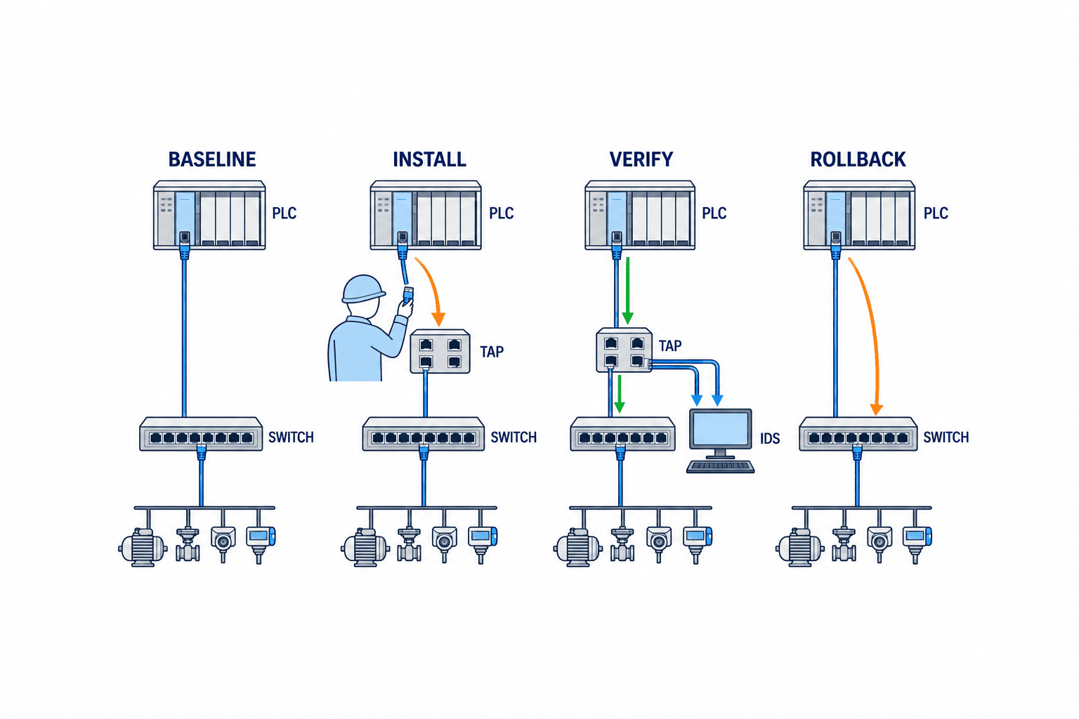
An inline TAP interrupts an existing connection during insertion. At the RFP stage, agree on an outage window, maximum permitted interruption, rollback trigger and witnesses with production, control engineering, network operations, safety and quality. A redundant design does not eliminate the need to inspect the exact link being cut; a shared segment may affect both apparent paths.
The work order should contain photographs, port identifiers, labels, TAP port orientation, power supplies, spare patch leads, switch configuration backup and a pre-change baseline. The sequence is: confirm safe stop, disconnect, insert, restore link, test PLC to HMI, inspect alarms, prove both monitoring directions, record results and hand operation back. Name the person who can stop the change. The rollback drawing must show the original direct connection, not merely say “remove TAP.”
After restoration, inspect control response, HMI display, MES integration, time synchronization, protocol errors, CRC and discards, and renegotiation counts. Agree on a post-change watch period because some symptoms appear only during a later production cycle. If the window is exceeded, return to change control rather than improvising repeated trials on a live line.
When an outage window is unavailable
Evaluate a suitable SPAN session first, using the exact switch’s source, destination, direction and capacity rules. If SPAN cannot meet the evidence requirement, schedule TAP insertion during a permitted shutdown or equipment renewal. The decision is driven by required evidence and production risk, not by a preference to buy a TAP immediately.
Write an RFP that exposes differences
“Industrial TAP, 1 Gbps, IDS ready” is not a comparable specification. Attach the link map and measured traffic assumptions. Require every vendor to reply in the same format and separate mandatory compliance from scored features. Compare price only among technically compliant options. Request separate lines for TAP, transceivers, cables, power, mounting, installation, outage support, FAT, SAT, training, spare units, warranty and maintenance. Do not copy unverified market prices into the business case.
- Observation: endpoint tags, normal and failover routes, both directions, VLANs and protocols.
- Physical: copper or fiber, speed, connectors, wavelength, optical split, PoE, cabinet environment and grounding.
- Copy output: breakout or aggregation, speed, packet rate, drop indicators, timestamps and IDS interface.
- Failure: power loss, one-sided loss, monitor disconnect, production cable loss, LFP, relay behavior and recovery.
- Security: prevention of return traffic, management port, authentication, logging, firmware and backup.
- Evidence: exact model and version, datasheet sections, wiring, optical budget, test sheets and training.
- Commercial: itemized quote, lead time, spares, replacement procedure, support and lifecycle.
Do not score an unsupported “compliant” checkbox. Ask for a drawing number, datasheet paragraph, test record, exception and workaround. Control engineers assess production impact; security assesses collection and storage; maintenance assesses replaceability. Conditional approval is appropriate for optical power, PoE and failure modes until the plant-specific tests pass.
Compare total cost of ownership
The TAP price is one component. A different monitor-port arrangement can change IDS NIC count or licensing. Fiber brings transceivers, patch leads, optical measurements and spares. Copper fail-safe and PoE require compatible models and tests. Use one evaluation period and consistent assumptions for installation, outage preparation, support, replacement, expansion and retirement. A low-cost TAP that leaves the sensor dropping packets does not meet the purpose.
Score visibility, continuity and serviceability separately
Do not rank bids by a simple count of features. First determine mandatory fit: production media, PoE, optical margin, the allowed outage and the path after power loss. Next score capture quality, including both directions, packet loss under peak load, timestamps and compatibility with the actual sensor. Then assess serviceability: spare-unit compatibility, replacement time, configuration restore, support and diagnostic logs. A bid with many monitoring features still fails if it cannot preserve the agreed production-link behavior.
For each answer, request its conditions, evidence, test date, owner and remaining risk rather than a “yes” checkbox. PoE support needs the applicable class, power, cable length and the device behavior after power returns. Fiber needs the direction of the split, loss at the operating wavelength and margin at the plant receiver. The monitor output needs a simultaneous two-way peak test, not only a rated speed. Apply the same evidence rule to a SPAN proposal: verify that its configuration survives restart, changes are controlled and the destination-port load can be monitored. Register the mirror setting or TAP cabling in change management.
Turn required conversations into acceptance scenarios
For a packaging line PLC and HMI, include ordinary operation, product changeover, recovery after a safe stop and equipment restart. In each scenario, inspect request and response, device identity, timestamps, arrival at the sensor and alarms. If MES traceability is the purpose, reconcile HMI actions, PLC events and MES records, and document traffic the observation point excludes. Test safety functions only through procedures approved by the machine maker and plant safety owner. A redundant network also needs an approved failover scenario: check whether traffic moves outside the observed link and whether capture-outage alerts tell the operator what became invisible.
Separate FAT from SAT
At FAT, use the purchased model, firmware, port arrangement and sensor in a vendor or controlled test setting. Test the wiring, both directions, peak load, power loss and return, monitor disconnect, and applicable PoE or LFP behavior. Fix the test traffic, instruments, logs, thresholds and recovery steps in a signed test sheet. FAT is not satisfied by a generic catalogue demonstration. A failed configuration should not proceed to site installation.
At SAT in the Thailand factory, verify integration with real cables, transceivers, power and control devices. Record pre- and post-change speed, CRC, discards, PLC to HMI response, MES records, both-way capture, time, optical power, IDS alerts and cabinet temperature. A FAT pass does not guarantee a SAT pass when polarity, PoE, switch settings or environment differ. Continue the agreed watch period before handover.
| Test | FAT evidence | SAT evidence |
|---|---|---|
| Both-way capture | Known A-to-B and B-to-A packets and sensor counts | Actual flows and production peak |
| Physical fit | Specified cable, optics and PoE under simulated faults | Actual link speed, optical power, PoE and CRC |
| Power and link fault | Timeline for off, on and cable failure | Control impact, alarms and rollback time |
| Security | Return-traffic test and management configuration | Management route, privileges and audit trail |
| Handover | Versioned wiring, maintenance and replacement steps | Training, spares, change record and owner |
Plant-specific acceptance numbers are essential. Define how long link restoration may take, which packet-loss interval is measured and how accurate timestamps must be, then have control and sensor owners approve the values. This article cannot supply universal thresholds. A reproducible result needs load profile, duration, clock and counter location as well as a target number.
Maintain observation quality after handover
A passing SAT is a baseline, not permanent proof. Added machines, changed switches, firmware, ring settings or MES traffic can change visibility. Periodically and after each change, check the link register, sensor receive and drop counters, both-way flows, clock status, storage and alert destination. Health-monitor the sensor itself so that a silent capture outage is not mistaken for a safe network.
Captured packets may include work orders, lot identifiers, product information or names. Set collection scope, location, retention, access and third-party sharing by purpose. Review classification and contracts before transferring OT captures outside the plant. Retain deletion evidence after raw packets are no longer needed. Troubleshooting and security teams may need different data granularity. Across multiple TAPs and sensors, document clock source, time zone, precision and synchronization failure; unsynchronized timestamps can misorder an incident. If control equipment cannot accept added time-sync traffic, use the sensor-management side to maintain the sensor clock.
Label the TAP and cables so maintenance cannot swap production and monitor ports. Include fiber cleaning and bend radius, copper grounding, cabinet temperature, power and spare-unit compatibility in the maintenance record. Define plant priorities for a fault: protect people and production, restore production communication, restore monitoring, then investigate the cause.
Related design decisions
The industrial Ethernet switch selection guide covers switch ports and functions. The industrial OT firewall selection guide covers inter-zone control. The industrial network redundancy guide covers alternate paths. A TAP should use these designs as inputs but does not itself implement segmentation, blocking or redundancy.
Frequently asked questions
Should a factory choose an industrial TAP or SPAN?
Start with the required flows and evidence. SPAN can be suitable if the exact switch and sensor meet both-direction capture and capacity needs without an outage. Compare an inline TAP when an independent observation point or specified failure behavior is needed. Validate either choice against measured traffic and change risk.
Is one 1 Gbps monitor port enough for a 1 Gbps TAP?
Not necessarily. Combining two directions of a full-duplex link may exceed the output’s capacity. Measure peaks and packets per second, then consider breakout outputs, a faster interface or more sensors.
Will a copper TAP preserve PLC traffic during a power failure?
It depends on the exact model and wiring. Test the relevant fail-safe or bypass mechanism, link renegotiation, controller timeouts and recovery. A vendor’s path-continuity claim is not a production-availability guarantee.
How should a fiber split ratio be chosen?
Use the production and monitor optical budgets, wavelength, fiber type, transceivers and measured connector losses. Draw which side receives each share and measure optical power during SAT.
Is a data-diode TAP always required for an IDS?
No universal rule applies. Consider it when hardware-enforced one-way flow is a requirement. Evaluate management ports and other routes as part of the complete system, and test whether return traffic is possible.
What belongs in the cost comparison?
Include TAP, monitor arrangement, IDS and NICs, cables and optics, power, outage work, FAT/SAT, training, spares, support and retirement over the same period. Use comparable vendor quotes against a site-specific RFP instead of unverified list prices.
Conclusion: accept visibility and production impact together
An industrial network TAP should be selected only after confirming that the desired conversations cross the proposed link. Compare SPAN on the same evidence basis; size both directions; verify copper, fiber and PoE; and test exact-model failure behavior. Plan the outage before purchase, prove device behavior in FAT, then prove integration and control continuity in SAT. Keep passive collection separate from IDS analysis so both can be maintained and audited.
TOMAS TECH can help a Thailand factory map existing links, compare TAP and SPAN, prepare a monitored-link register and write practical RFP and FAT/SAT criteria. Even if the link and outage window are still undecided, contact us to discuss the options.
Primary sources
- NIST, SP 800-82 Rev. 3 Final: https://nvlpubs.nist.gov/nistpubs/SpecialPublications/NIST.SP.800-82r3.pdf
- Cisco, Catalyst IE3x00 SPAN/RSPAN: https://www.cisco.com/c/en/us/td/docs/IIOT/switches/ie3x00/config/layer2/layer2_switch/g_configuring-span-and-rspan/span-rspan-info.html
- Cisco, Nexus 9000 SPAN configuration: https://www.cisco.com/c/en/us/td/docs/switches/datacenter/nexus9000/sw/106x/config-guides/sys-mgmt/cisco-nexus-9000-series-nx-os-system-management-configuration-guide-release-106x/m-configuring-span.html
- Garland Technology, Copper Failsafe: https://www.garlandtechnology.com/copper-failsafe
- Garland Technology, Data Diode Network TAP: https://www.garlandtechnology.com/products/data-diode-network-tap
- Keysight, Media Converter TAP: https://www.keysight.com/zz/en/products/network-visibility/network-taps/media-converter.html


