


When a factory’s 4–20 mA value jumps, replacing the sensor or PLC input card may seem obvious. Yet a difference in grounding between field and cabinet, two devices feeding one loop, or insufficient voltage after adding equipment can recreate the fault. Selecting a 4–20 mA signal isolator therefore requires checking active/passive connections, power, loop load, any needed HART communication, and fault output alongside the isolation boundary. This guide turns those decisions into an RFP and FAT/SAT plan for OT data collection in a Thai factory.
Draw the whole loop before adding an isolator
A 4–20 mA loop conveys a measurement as current between a field transmitter and a receiver such as a PLC. Analog Devices describes its wide industrial use for remote sensing. The fact that a current loop tolerates some electrical noise does not remove the need to design wiring, grounding and load. An isolator passes the signal while separating specified circuits electrically, but insertion may change how each side receives power.
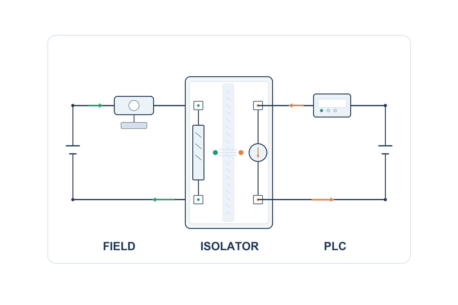
Put the transmitter model, two- or four-wire arrangement, loop power source, active or passive PLC input, supply, fuses, terminals, cable length, shield, grounding, local display and recorder on one drawing. Phoenix Contact’s technical diagrams show that “4–20 mA” includes active and passive inputs as well as isolators powered from the input loop, output loop or auxiliary supply. The word “isolator” in a product name cannot determine its correct connection point.
| On the drawing | Check before ordering | If omitted |
|---|---|---|
| Transmitter | Two/four wires, minimum voltage, active/passive | Undervoltage or two power sources |
| PLC input | Active/passive, input resistance, range and diagnostics | No reading or incorrect scaling |
| Isolator | Input/output powering, isolation boundaries, load limits | An incomplete loop |
| Wiring | Cable, terminals, shield and grounding | Ground paths or maintenance miswiring |
| Communication | HART requirement and access point | Analog values remain while diagnostics disappear |
Define the problem that isolation should solve
Different ground potentials between field equipment and cabinet can create an unintended current path. Phoenix Contact explains that galvanic separation can interrupt the path of compensating current in an analog ground loop. Isolation does not remove every possible disturbance. Nearby variable-speed-drive cables, shield termination, supply ripple, transmitter faults and PLC range settings remain separate hypotheses.
Before and after installation, record field-terminal current, receiving-side current or scaled value, supply voltage, grounding state and the time of each disturbance. If a value jumps only when a motor starts, observe the power and signal at the same time. If the field-side current stays correct but the PLC-side value does not, focus on the cable and receiver path. If both change, retain the process and sensor as possible causes. Installing an isolator without this diagnosis can hide an unresolved fault.
Isolation boundaries are not safety functions
“Two-way isolation” and “three-way isolation” describe separated circuits; inspect the actual product block diagram. Typically the former separates input and output, while the latter separates input, output and auxiliary power, but specific powering and ratings depend on the model. Phoenix Contact lists both a loop-powered two-way model and an auxiliary-powered three-way model. The larger number is not automatically better for a given circuit.
Galvanic isolation of a measurement does not by itself implement a machine safety stop, intrinsic safety in a hazardous area, surge protection or overcurrent protection. A hazardous-area installation needs a suitable certified barrier and approved wiring. Do not substitute a general-purpose isolator for an Ex barrier. For a safety-related loop, evaluate component certification and failure behavior within the full safety function.
Match active/passive interfaces and powering
Active and passive identify which part supplies energy to the loop, not quality grades. A two-wire transmitter commonly uses the same two conductors for power and signal. A four-wire transmitter has a separate supply and may have an active current output. A receiving card may be an active input that powers the field side or a passive current receiver. Phoenix Contact gives wiring examples involving an active transmitter, passive conditioner input, active output and passive receiver.
An RFP needs more than “4–20 mA compatible.” Ask whether the conditioner powers the transmitter on its input, is powered by an active PLC input on its output, or needs an auxiliary 24 V DC supply. Specify the output on wire break and loss of power. Require a terminal-numbered wiring diagram. If the bidder has not seen the transmitter and PLC input models, compatibility is still unproven; provide their manuals and existing drawings.
Check the voltage cost of loop-powered models
A loop-powered isolator can eliminate a separate supply but uses voltage from a loop. One Phoenix Contact output-loop-powered model is intended to operate from an active controller input. The same family may contain input-loop-powered and externally supplied alternatives. Calculate transmitter minimum voltage, isolator drop, PLC input resistance and cable drop under the maximum relevant current. A model name is not enough.
When many channels share a power supply, check total supply current, startup, fuses and common terminal ratings as well as each loop. Decide whether a fault on one channel affects others and what a shared power failure will record. A single-channel bench test is not proof that an entire cabinet will operate correctly.
Calculate loop-voltage margin explicitly
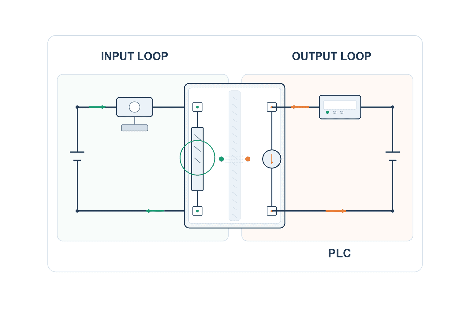
For one electrical loop, organize the budget as supply voltage ≥ transmitter minimum voltage + receiver-resistor drop + isolator requirement + cable/protection drop. Use values specified at compatible current and temperature conditions. An isolator may separate input and output into different electrical loops; calculate each separately. Do not assume every component is simply in series on one 24 V supply.
For an illustrative assumption, calculate the galvanically separated input and output loops independently. On the field/input side, assume a 24.0 V DC field supply, a two-wire transmitter needing at least 12.0 V, 100 Ω isolator input burden, and 1.0 V drop in field-side cable and protection. At 20 mA = 0.020 A, the input burden drops 0.020 A × 100 Ω = 2.0 V; field-side margin is 24.0 − 12.0 − 2.0 − 1.0 = 9.0 V. On the separate controller/output side, assume a 24.0 V DC cabinet supply, an illustrative output-loop-powered isolator needing at least 8.0 V, a passive PLC input of 250 Ω, and 1.0 V drop in output-side cable and protection. The PLC input drops 0.020 A × 250 Ω = 5.0 V; controller-side margin is 24.0 − 8.0 − 5.0 − 1.0 = 10.0 V. The PLC resistor does not belong in the input-side budget. These two circuits and the 8.0 V figure are hypothetical teaching inputs, not the wiring or guaranteed specification of a named model. An auxiliary-powered three-way model requires its own input, output and auxiliary supply checks against its terminal drawing and load specification. For actual design, recalculate using minimum supplies, maximum or relevant fault current, ambient temperature and actual input resistance.
A second isolator placed in a genuinely series path would reduce the margin further under these assumptions. Many isolators, however, create separate powered input and output loops. Mark each voltage-drop term on the circuit and budget the side that powers it. Even a positive calculated margin may be too small for supply variation or future cable changes; set acceptance margin from the machine’s conditions.
Verify accuracy, response and HART by model
The transmitter, isolator and PLC input each contribute to total measurement uncertainty. A claimed “0.1% accuracy” needs its reference: span, reading or full scale; calibrated state; and temperature. Phoenix Contact publishes model-specific maximum transmission error and temperature coefficient. Transcribe the conditions into the comparison, then evaluate the complete chain. Do not add unlike percentage definitions and call the result a valid total error.
Response time matters separately. A small delay may be irrelevant to slow temperature logging but material for rapidly changing pressure or a protective function. Isolators differ in step response and frequency limit. Strong filtering can reduce brief jumps while also delaying real changes. Specify the measurement’s use, alarm timing and needed response before selecting filtering.
If HART is required, reading the analog current is not proof that digital communication passes. Phoenix Contact labels particular models HART-transparent; this is a model-specific property, not a feature of every isolator. Define where a handheld unit or asset-management system will connect, check the input/output card and wiring, and communicate with a real field device during FAT and SAT. If HART is not needed, compare the cost of simpler products without imposing it by habit.
Specify the meaning of fault output
A broken transmitter wire, loss of transmitter power, out-of-range input, isolator failure and PLC input fault need different interpretations. Whether an isolator produces 0 mA, holds the last value or moves toward a fault level depends on model and configuration. If a PLC or MES stores “measurement zero” when the value is actually invalid, the quality record becomes misleading. Store measurement, time, quality state, reason for invalidity and recovery separately. Define detectable and undetectable faults and their alarm mapping; do not apply one vendor’s numerical fault range to every transmitter.
Compare cabinet integration and maintenance
DIN-rail width is only one cabinet constraint. Leave room for wiring, ventilation, terminal replacement and readable indicators. Weidmüller lists a narrow three-way amplifier; Phoenix Contact lists loop-powered and auxiliary-powered models with different terminals. Review total width, adjacent-device temperature, power distribution, spare channels and readable terminal IDs. Use the actual cabinet design temperature in Thailand, not a countrywide assumption.
For replacement, compare input/output active/passive status, isolation boundaries, ranges, terminals, HART support and fault behavior. Even an advertised successor part may have changed connection conditions. Photograph DIP switch settings or save configuration, linked to the actual test result. Check availability and lead time for local spares.
Design shielding and grounding outside the isolator
Other ground paths can remain through cable shields or device housings. Follow the system grounding design and manufacturer wiring instructions; neither “ground shields at one end” nor “ground them at both ends” is universal. Record the actual connections on the drawing. Where surges or large transients are credible, review separate surge protection and physical cable segregation.
Write input, output and test conditions into the RFP
Avoid an order line such as “4–20 mA isolator as appropriate.” Provide transmitter and PLC models, power arrangement, loop-voltage budget, desired boundary, error and response limits, HART need, fault output, cabinet conditions, certifications and test conditions. Require wiring diagrams, settings, bill of materials, data sheets and an FAT/SAT plan in the reply.
| RFP field | Buyer provides | Supplier proves |
|---|---|---|
| Source/receiver | Models, two/four wires, active/passive | Terminal-numbered drawing |
| Power/load | Minimum supply, resistance, cable, margin | Separate budgets for each loop |
| Isolation | Boundary and environment | Topology, ratings and test conditions |
| Performance | Error, temperature, response, HART | Data sheet against requirement |
| Failure | Wire break and power-loss recording | Fault-injection plan |
| Maintenance | Terminals, DIP settings, spares | Settings and replacement method |
| Acceptance | FAT/SAT points | Measured logs and pass criteria |
A cheap part may need another power supply or cabinet modification. A premium HART-capable part may be unnecessary if no HART data are used. Compare installed cost, wiring, shutdown, tests and spares on the same basis. Estimate business benefit from current missing-data events, repeat measurements and quality hold time rather than a promise that isolation will remove all noise.
Implementation decisions that protect data meaning
Keep scaling consistent from transmitter to history screen
The transmitter range determines what 4 and 20 mA mean physically. A conditioner with conversion may have different input and output ranges; the PLC may then scale again, and a historian may apply another conversion. For an illustrative setting of 4 mA = 0 and 20 mA = 100, 12 mA represents (12−4)/(20−4) = 0.5 of span, or 50. Whether 50 means °C, bar gauge or bar absolute remains essential. Version the range and unit across the whole system and check 4, 12 and 20 mA at FAT.
Splitting one signal to two PLCs by adding two receivers in series increases load. Consider a purpose-designed dual-output isolator or distribution through a data system, and assess failure on either receiving side. Weidmüller’s ACT20M-AI-2AO-S (order 1176020000) has two isolated outputs; its datasheet identifies active outputs requiring passive receiving inputs. Order 1176010000 denotes a different, single-output model. Suitability still depends on receiver power and load. Avoid adding electrical load to a field transmitter every time another consumer wants data.
Give “invalid” its own quality state
When data reach a PLC or MES, they need a quality flag as well as a number. On wire break, a system might show the last good value or a fault-side value. Saving either as an ordinary measurement obscures what the process actually did. Store invalid-period start and end, reason and recovery separately. For quality-critical variables, agree how to identify lots processed while evidence was unavailable.
Adding filtering can change alarm response. Suppressing a short spike may help, but it could also remove a genuine short event. If one point is used for control, monitoring and quality release, state each function’s timing requirement. MES sampling and clock alignment are acceptance criteria separate from analog electrical accuracy.
Link part changes to backup and change control
Before modifying a cabinet, save existing wiring, PLC scaling, alarm rules, HART settings and history tags. A temporary test can pass, yet final wiring can change polarity or terminals. A change plan should list isolation, absence-of-voltage verification, replacement, wiring check, energization, current injection, PLC/MES check and return to service, together with owners and rollback. When changing several channels, check each tag and terminal separately to avoid crossing instruments.
If cable or PLC card changes after FAT, a test assumption has changed. Record the delta and repeat the affected checks. Use the side of the isolator affected, power arrangement and HART path to decide scope. A change record also gives a useful starting point if noise recurs months later.
Local procurement and spares are performance requirements
For several sites in Thailand, ask where the exact part can be bought, whether technical documents are available locally, and how long replacement takes. A compact module may be costly to operate if its special base terminal is unavailable. For an approved substitute, list powering, isolation, input/output load, fault output, response and HART as equivalence conditions. Similar dimensions are insufficient.
Provide spare-channel capacity without merging unrelated signals into one terminal. Preserve the mapping among physical instrument tag, terminal, PLC variable and MES history. Deliver that mapping; it helps both traceability and future calibration.
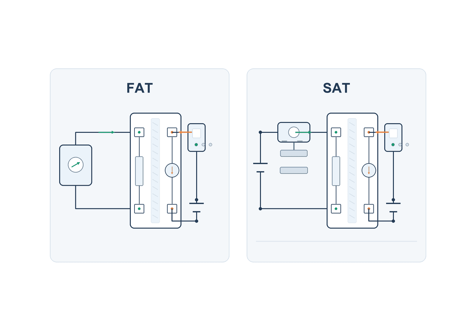
FAT: test 4 mA, midspan, 20 mA and faults together
Use a calibrated current source or suitable simulator to apply 4 mA, a midpoint and 20 mA. Record the isolator output and the PLC’s engineering-unit value. Capture source setting, instrument identifier, PLC range, temperature and supply. Where needed, check rising and falling directions, response and startup transients. Pass limits come from complete-system requirements, not automatically from a component’s accuracy specification.
Then inject permitted faults separately: open a loop, remove transmitter supply or remove isolator auxiliary power according to the approved risk assessment and procedure. Check whether PLC/MES hold a number or mark it invalid. If HART is required, actually read parameters and diagnostics from the intended access point. If long site wiring or grounding cannot be reproduced at FAT, record the item as unverified and carry it into SAT.
SAT: repeat under installed cable, ground and noise conditions
Use actual cable length, shield termination, cabinet power and realistic inverter or large-load operation. Repeat 4 mA, midpoint and 20 mA checks, then record restart values and the real field transmitter value separately. Connecting a simulator at the site may affect process control; follow isolation and operating permits and avoid fault injection while a machine could move unexpectedly.
After noise decreases, confirm data meaning. Check PLC scaling, aligned trend timestamps, wire-break records and process alarm thresholds. A plausible normal value is not proof that quality history and exception records remain intact. Give maintenance the terminal drawing and setting sheet, and retain baseline waveforms and logs.
| Symptom | Check first | Avoid assuming |
|---|---|---|
| 0 mA/no value | Power, open wire, active/passive, polarity | The transmitter has failed |
| Stuck near 4 mA | Minimum transmitter voltage, loop margin, load | Only the PLC scale is wrong |
| Periodic oscillation | Timing of large loads, wiring, shield, input setup | Isolation removes all noise |
| Analog good, HART absent | Transparent model, access point, card | 4–20 mA compatibility means HART |
| Scale changes after replacement | Range, DIP setting, active/passive, calibration | A successor needs no retest |
Change one wiring or configuration variable at a time. Compare before-and-after current and voltage at the same points. Trace from transmitter output to isolator input, isolator output and PLC scaled value to locate where the difference starts.
Translate common project types into requirements
For an existing pressure transmitter that jumps only at motor startup, identify event times, measure current simultaneously at the field terminal and PLC, and check supply, shield and ground. A stable field current with a disturbed cabinet reading points toward wiring and receiving equipment; matching disturbances retain the sensor or real process as possibilities. Preserve waveforms, then compare under the same operation after modification. Quote the isolator, power, terminals, wiring, shutdown, injection and trend comparison. Do not promise “zero noise”; define measurable acceptance for the reproduced event. If the motor condition cannot be recreated at FAT, SAT must decide it.
For a new line with many temperature, pressure and flow instruments, build a signal list. Each row needs a tag, unit, meaning of 4 and 20 mA, two/four-wire arrangement, power source, accuracy, response, HART, wire-break behavior and calibration method. Choose input cards and isolators from that list and calculate voltage by channel. Map instrument tags to PLC variables and MES history records. Inject a known current one channel at a time at FAT to catch swapped tags; validate installed instruments and process conditions at SAT.
If the signal decides product acceptance or lot hold, an isolator fault must not end as a generic equipment alarm. Record the missing-evidence interval and identify the work processed during it. Quality should decide the exception workflow, including whether a single healthy value after recovery can release anything. These data-collection rules are not provided by an isolator catalog.
Related reading and FAQ
For the physical temperature-measurement method and thermowell, see our industrial temperature sensor guide. For digital conversion among industrial protocols, see our industrial protocol gateway guide. This article addresses electrical separation and evidence for one analog current loop.
Do all 4–20 mA isolators connect in the same way?
No. Active/passive input and output, loop-power source, auxiliary supply and two- or three-way isolation differ by model. Confirm the exact transmitter and PLC card on a terminal-numbered drawing and calculate each powered loop.
Is three-way isolation always safer than two-way?
No. The term describes separated circuits; it does not prove a safety function or hazardous-area approval. Select boundaries, ratings, certification and powering for the actual application.
Does adding an isolator preserve HART?
It depends on the model. Choose one explicitly specified as HART-transparent and test communication from the real access point during FAT/SAT. Reading the analog value alone is insufficient.
Is a nominal 24 V supply always enough?
No. Use minimum supply, transmitter minimum voltage, input resistance, isolator requirement and cable drop at relevant maximum current. Calculate electrically separate input and output loops separately.
Conclusion
A 4–20 mA signal isolator is selected for a defined electrical loop, not by the promise of generic noise removal. Draw power and current paths from field transmitter to PLC, then specify active/passive status, isolation boundary, voltage budget, error, response, HART and fault output. FAT injects known currents and faults; SAT repeats checks with real cable, grounding and operational noise.
If an existing measurement in your Thai factory is unstable, or you are specifying a new OT data-acquisition cabinet, the transmitter model, PLC card, power and wiring diagram provide a useful starting point. Contact TOMAS TECH with the loop and conditions you need to measure.
Sources
- Phoenix Contact, Digital and analog signal conditioning.
- Phoenix Contact, 2-way loop-powered conditioner.
- Phoenix Contact, configurable three-way 4–20 mA input/output conditioner 2864163.
- Phoenix Contact, HART-transparent isolator.
- Weidmüller, ACT20M-AI-2AO-S, order 1176020000 (official PDF).
- Weidmüller, ACT20M-AI-AO-E-S, order 1176010000 (official PDF) — single-output three-way example.
- Analog Devices, 4–20 mA current-loop transmitter.
- Analog Devices, 4–20 mA transmitter implementation.


