


Successful heavy-load conveyor automation does not begin by choosing a machine whose brochure says “maximum 3,000 kg.” It begins by converting the real risks into numbers and verifiable evidence: where the load concentrates, how the workpiece is retained while stopped, what happens at a transfer gap, how a jam can be recovered without improvisation, and whether the floor and foundation can withstand concentrated and repeated loads. This guide is for production engineering, facilities and procurement teams in Thailand that must move battery packs, e-axles, dies, large fixtures or similar workpieces in the 3,000 kg class. It takes the project from the heavy-load transport RFP through FAT and SAT.
What the September 2026 TS 7plus story does—and does not—tell us
On 11 September 2026, an Association for Advancing Automation (A3) / Automate.org page authored by Bosch Rexroth Corporation announced exhibits for The Battery Show 2026 and described the TS 7plus roller conveyor as capable of carrying workpieces up to 3,000 kg. This was a trade-show announcement, not the original product launch. Bosch Rexroth’s official TS 7plus launch release is dated 31 March 2026. The dates should not be conflated.
Bosch Rexroth’s official product page and launch release state the following headline figures.
| Item | Vendor-published figure | What the project must still establish |
|---|---|---|
| Maximum conveying load | Up to 3,000 kg | Actual mass including workpiece, pallet and fixture; eccentric load; dynamic factor |
| Standard workpiece-pallet size | Up to 2,200 × 3,000 mm | Support points, deflection, underside geometry and pose tolerance |
| Conveyor speed | Up to 24 m/min | Acceleration, stop distance, cycle time, safety distance and transfer speed |
| Minimum transport height | 350 mm | Ergonomics, maintenance access, pit and floor interference |
| Motors | 180 W / 250 W | Zone length, simultaneous loads, slope, friction, start frequency and temperature |
These are vendor-published capabilities for the TS 7plus. They do not mean that every configuration can carry 3,000 kg at 24 m/min in every environment. Whether maximum values can occur together, how many loaded pallets can run simultaneously, and what stopping accuracy or transfer impact can be achieved must be confirmed by selection calculations and testing. Claims such as “world’s first,” lower TCO and high availability are also the vendor’s positioning. This article does not recommend one product; it uses the announcement to show how a purchaser should build requirements.
For general conveyor types and speed selection, see our conveyor system design guide for Thailand. This article deliberately stays with the failure boundaries specific to approximately 3,000 kg workpieces.
Define a load envelope, not only a maximum weight
If an RFP says only “maximum load: 3,000 kg,” the supplier may assume a uniformly distributed load while the owner imagines the worst offset condition. A usable requirement is not one mass value but a load envelope combining every state that can reasonably occur during transport.
For every workpiece family, provide at least:
- minimum, nominal and maximum mass including workpiece, pallet, fixture, temporary restraints and retained fluid;
- length, width, height and X/Y/Z centre-of-gravity coordinates, including tolerance;
- number and location of support points, contact area, underside steps, hardness and allowable contact pressure;
- transport orientation and the poses created by forward, reverse, rotary and transverse transfer;
- workpiece stiffness, allowable deflection, and no-contact areas such as precision faces or connectors;
- temperature, dust, oil, chips, humidity, cleaning chemicals and conductive-debris conditions; and
- reasonably foreseeable abnormalities such as one support foot lifting, a missing pad or a shifted workpiece.
A rectangular bounding box alone is inadequate. Two battery packs with the same outer dimensions can have different centres of gravity and support reactions because of cell, cooling plate, enclosure and fixture layouts. A die may concentrate its entire weight on small feet. A large casting may have an uneven underside that creates local impact on rollers. Attach an underside view showing support points and the projected centre of gravity in every conveying pose.
Verify concentrated loads and support reactions first
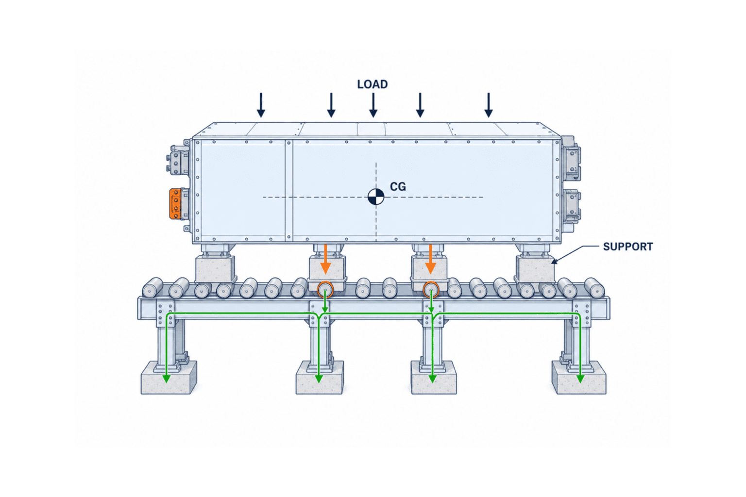
A system may be within its total kilogram rating and still fail when load concentrates on one roller, bearing block, pallet plate or stop gate. Check local reactions separately from the system-level mass rating.
Illustrative screening calculation
The following is an example of the method, not a final structural calculation.
- Workpiece + pallet + fixture mass: 3,000 kg (assumption)
- Gravitational acceleration: 9.81 m/s²
- Static weight: 3,000 × 9.81 = 29.43 kN
- Preliminary dynamic factor covering acceleration, stopping, fit-up error and load transfer: 1.3 (assumption)
- Screening design load: 29.43 × 1.3 = 38.26 kN
If four feet shared this perfectly, each would carry 9.57 kN. In reality, floor, pallet and workpiece deflection can create near three-point support. An offset centre of gravity can make the highest foot reaction much greater than the average. Do not specify only “divide by four.” Require the supplier to show worst-case reactions using an appropriate method—rigid-body statics, finite-element analysis or instrumented load-cell testing.
On a roller conveyor, the combination of foot spacing and roller pitch may leave only two rollers carrying the load at one instant. At a transfer gap, the number of supports decreases; an impact at a height mismatch increases dynamic reaction. The RFP should request:
- maximum roller reaction for each transport pose and transfer state;
- allowable loads and design margin for rollers, shafts, bearings, support frames and joints;
- pallet deflection and confirmation that its underside will not bottom between rollers;
- abnormal cases including eccentric loading and a missing support foot; and
- the assumptions and sources for friction, dynamic factors and material properties.
A catalogue line saying “up to 3,000 kg” does not answer these questions. Give every bidder the same load-case table so proposals are comparable.
Do not rely on the motor brake alone for stopped-load retention
Heavy workpieces may spend more time waiting in front of assembly, inspection or tightening stations than moving. During a stop, motor deceleration, drivetrain backlash, roller friction, stop gates, positioning units and fixture clamps serve different functions.
Separate at least five requirements:
- transport stop: decelerate and stop near a target;
- accumulation retention: prevent movement despite following-load pressure or small floor slope;
- process positioning: locate against datums with the repeatability needed for robots, fastening or measurement;
- safety restraint: prevent unintended movement when a person may enter a hazardous area; and
- state after energy isolation: define behaviour during power loss, communications loss, emergency stop and maintenance lockout.
A brake motor does not necessarily restrain a workpiece if backlash or a failure exists between motor and load. Conversely, driving a heavy pallet into a hard stop at speed can damage both. Define the function chain: detect the deceleration point, enter at controlled low speed, receive the load mechanically and, where necessary, locate and clamp it.
FAT should use maximum mass, worst centre of gravity, minimum expected friction, continuous accumulation, power loss, emergency stop and restart—not only the nominal pallet. Agree whether power restoration permits automatic restart or requires a manual reconciliation of occupancy, restraints and process state.
Translate “zero-pressure accumulation” and segmented drive into tests
Bosch Rexroth describes demand-driven segmented operation for the TS 7plus and refers to zero-pressure accumulation on its battery-production page. These are product descriptions; they are not a project guarantee.
The purchaser should turn the terminology into observable acceptance behaviour:
- how many loaded pallets can accumulate without contact;
- how far upstream the line stops when a photoeye fails or remains blocked;
- how two pallets are prevented from entering one zone;
- whether physical occupancy or database state prevails if they disagree;
- whether local control continues or stops safely when communications fail;
- how workpiece ID, location and process state are reconciled after power returns; and
- whether acceleration profiles change for empty and fully loaded pallets.
Energy claims also need a measurement boundary. Do not compare only motor ratings. Include the representative transport pattern, idle state, simultaneous starts, regeneration, controls, cooling and compressed air, if any. Any annual energy estimate must state assumptions for operating hours and load distribution.
The greatest large-workpiece risk is usually at the transfer boundary
A straight conveyor may work while the interfaces to lift, transverse transfer, rotary table, positioning station, AMR, crane, robot or test stand fail. Two machines can each be “rated for 3,000 kg” and still be unable to exchange a pallet safely if height, speed, centreline and support sequence differ.
Freeze these transfer-interface parameters
| Requirement | What must be fixed | FAT/SAT evidence |
|---|---|---|
| Height | Datum, permitted step and actual loaded height | Measurements at corners and centre |
| Centreline | Lateral/angular offset and stop repeatability | Repeated worst-offset trials |
| Speed | Sending/receiving speeds and synchronization tolerance | Trend, video and PLC log |
| Support | Minimum supports while crossing the gap | Load-case drawing and reaction calculation |
| Handshake | Ready/Busy/Occupied/Fault/Permit | I/O list and injected-fault log |
| Rollback prevention | Restraint under slope, drive loss or error | Power-loss and brake tests |
| ID transfer | Point where workpiece ID and process state transfer | Correlated MES/PLC log |
Control ownership must also be unambiguous. Define whether the sending machine pushes or the receiving machine pulls, and which controller owns the pallet while it bridges both. A design in which both PLCs lead, or both wait indefinitely for the other, creates jams and restart confusion.
Do not make “the operator will sort it out” the jam-recovery plan
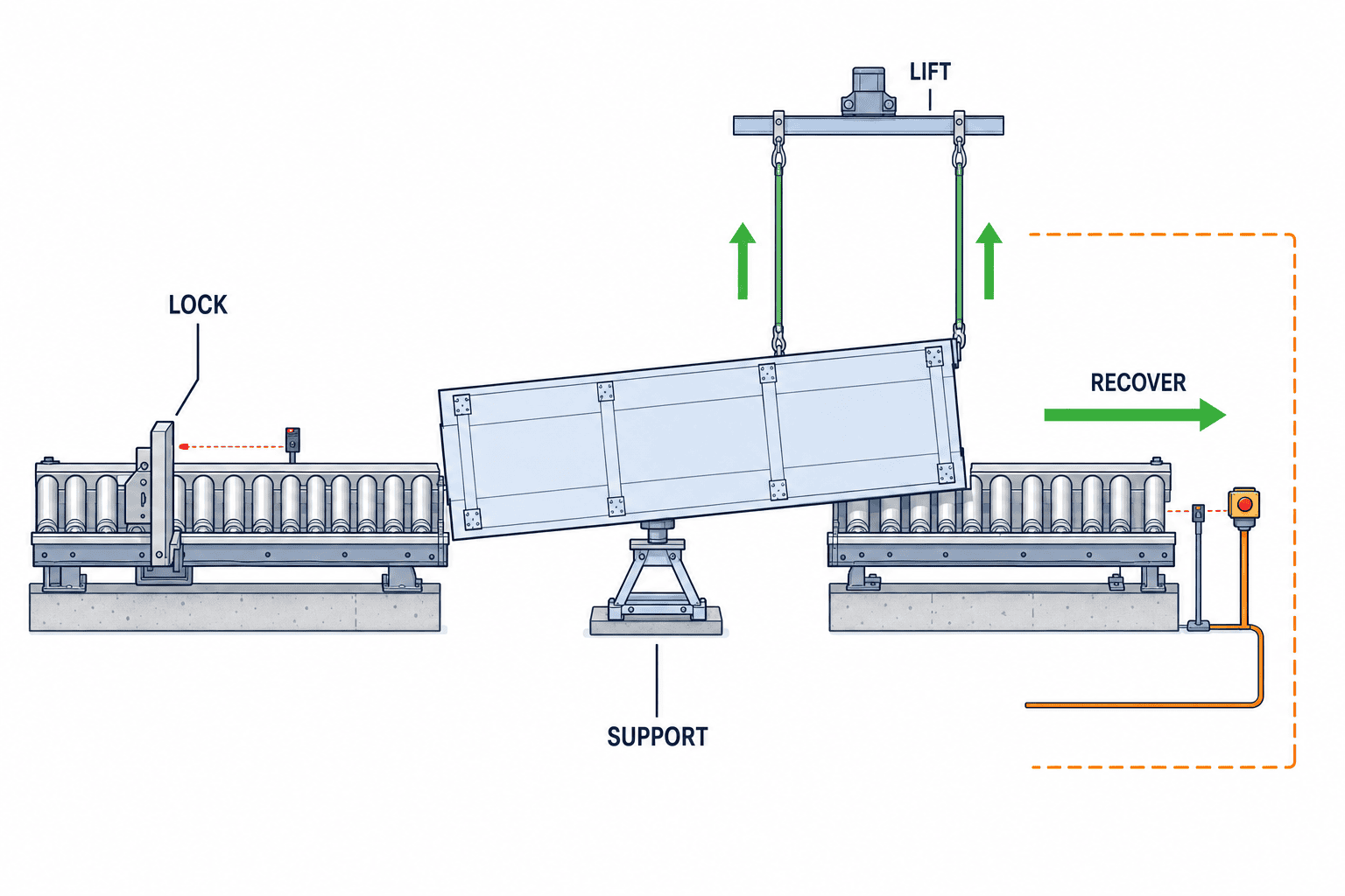
A 3,000 kg jam cannot be pushed back by hand. Improvised recovery—bringing in a forklift at an angle, pulling with a crane, bypassing a sensor—raises both equipment and personnel risk. Design recovery methods into the machine at RFP stage.
Representative fault modes include:
- a pallet stopping across two conveyor zones;
- skew caused by a failed roller or one-sided drive;
- a stop gate stuck up or down;
- a broken pallet foot that removes a normal support point;
- digital ID transferring to the next process while the physical pallet remains behind;
- a battery-pack abnormality that prohibits further transport; and
- all zones stopping after power, network or safety-device loss.
For each mode define the hazard, detection, stopped state, isolation boundary, residual energy, recovery fixture, lifting points, access, staffing, authority and restart checks. If a forklift or crane is part of recovery, include approach space, floor loading, certified fixture, load rating, interference and procedure in the design.
Manual mode is not a mode that disables safety. Based on risk assessment, it may require reduced speed, hold-to-run control, direct local visibility, restricted direction, one action per command, key control and two-person confirmation. ISO 12100 provides a general lifecycle method for hazard identification, risk estimation/evaluation and reduction. It does not choose the detailed measure for a particular conveyor; that depends on the machine, application and local requirements.
Do not judge the floor and foundation only by static kg/m²
A heavy-load line places the workpiece, conveyor, pallet, fixture, service tool, personnel and adjacent equipment on the floor. Concentrated reactions occur at the feet. Acceleration and transfer create horizontal forces, while repeated loading acts on anchors and grout.
The equipment-to-civil load schedule should include:
- maximum and minimum vertical reaction and uplift at every foot;
- X/Y horizontal forces, overturning moment, and treatment of seismic or impact cases;
- normal, maximum-load, jam, maintenance and lifting cases;
- anchor coordinates, baseplate dimensions, leveling range and grout conditions;
- allowable settlement, step and slope, plus survey datums; and
- survey scope for slab thickness, reinforcement, joints, embedded services, pits and chemical deterioration.
As an illustration, if one foot carries 20 kN over 0.02 m², average bearing pressure is 1 MPa. This simple value is not a structural approval. Baseplate bending, local concrete bearing, punching, anchor edge distance, existing cracks and cyclic effects require evaluation by qualified building/structural personnel together with the owner.
Survey elevation and alignment before SAT and again after loaded running. To detect early settlement or anchor loosening, include follow-up surveys—for example at 30 and 90 days—in the maintenance plan. These periods are examples; actual timing follows floor conditions and supplier guidance.
Turn maintainability into availability evidence
Replacing one roller or sensor can stop a heavy-load line for hours if the loaded workpiece cannot be removed. Maintainability should be demonstrated with real tasks, not a promotional mean-time-to-repair number.
Request:
- a method to remove a fully loaded pallet stopped in every critical zone;
- replacement envelope for motors, rollers, bearings, sensors and stop gates;
- how much adjacent equipment must be dismantled;
- a list of lifting fixtures, jacks, stands, lock pins and special tools;
- recommended spares, local stock and Thai versus overseas lead time;
- diagnostic points, alarms, condition-monitoring signals and replacement limits;
- Thai and English procedures with photographs, hazards and LOTO points; and
- substitution and software compatibility if a component is discontinued.
During FAT, actually replace at least one representative component and record the time and deviations from LOTO start through restart verification. During SAT, have plant maintenance personnel repeat the task with real tools, access, lighting, platform and language conditions.
Battery-factory transport needs state-based zones
A battery pack is not merely a heavy box. Depending on process state, the line may need to manage energization, retained energy, short circuit, insulation, coolant leak, heating, smoke, gas and damaged-product isolation. Controls vary with chemistry, state of charge, cell/module/pack state, process, fire/building conditions, customer rules and local law. No single explosion-protection or suppression specification can be prescribed from this article.
Divide the route into state zones such as:
- non-energized or mainly mechanical assembly transport;
- energized products after electrical connection or testing;
- temporary stop and isolation for suspected abnormalities;
- emergency response for confirmed damage, heating or leakage; and
- controlled maintenance/recovery areas.
For each zone define entry permission, maximum dwell time, necessary temperature/smoke/gas/leak detection, ventilation, drainage, fire compartmentation, evacuation, emergency response, stop logic and isolation destination. If a sensor is unknown, communication fails or workpiece ID cannot be read, the system should not silently treat the pallet as normal. EHS, fire protection, equipment, product safety, quality and competent specialists must decide the transition through risk assessment.
Stopping an abnormal pack in the middle of the main line may block following workpieces and an escape route. Consider a divertible isolation bay, handover point, remote observation and manual recovery equipment in the initial layout. Isolation capacity, maximum dwell, monitoring ownership and release prohibition become FAT/SAT criteria.
Compare fixed conveyor and AGV/AMR on more than payload
A fixed conveyor often suits a fixed, high-frequency route with repeatable positioning. An AGV/AMR can support routing changes and multiple destinations. At heavy payloads, however, floor condition, docking accuracy, transfer stability, charging, traffic, rescue and turning space become controlling factors.
ISO 3691-4:2023 covers safety requirements and verification for driverless industrial trucks and their systems, including AGVs and AMRs. Its scope explicitly excludes trucks guided solely by mechanical means such as rails or guides. It is not a blanket fixed-conveyor standard, and a replacement draft is under development. When an AGV/AMR is in scope, confirm the edition, regional adoption, customer requirements and whole-system risk assessment.
| Axis | Fixed conveyor checks | AGV/AMR checks |
|---|---|---|
| Throughput | Zones, accumulation and bottleneck | Fleet size, traffic, charging and call delay |
| Transfer | Fixed height and centreline accuracy | Docking repeatability, floor change and load transfer |
| Safety | Guards, openings, stop and retention | Person detection, speed, operating zone and intersections |
| Recovery | Zone bypass and recovery fixtures | Rescue, towing, manual operation and network loss |
| Changeability | Modular extension and relocation | Route/station addition and map control |
| Building | Foundation, anchors and fixed footprint | Flatness, steps, aisle width and chargers |
See our material-handling equipment selection guide for the broader comparison method. If an AMR hands a pallet to a fixed line, our conveyor-top AMR integration guide covers the interface in more detail.
Twelve data packs for a heavy-load conveyor RFP
A good RFP is not a request for suppliers to “propose a solution.” It supplies comparable design inputs and evidence formats.
1. Workpiece and pallet register
For each model show mass, dimensions, centre of gravity, supports, underside, permitted pose, lifting points and no-contact faces. Put future envelope models on separate rows.
2. Volume and scenarios
Provide peak windows, batches, changeover, rework, empty pallets, abnormal accumulation and future growth—not only averages. Translate takt into simultaneous occupancy and accumulation distribution.
3. Layout and building datum
Provide surveyed coordinates, floor levels, columns, joints, pits, doors, escape paths, forklift traffic, cranes, utilities and maintenance routes. State drawing accuracy and unresolved items.
4. Process interfaces
Define upstream/downstream height, speed, position tolerance, Ready/Busy/Fault, workpiece ID, quality state and ownership transfer.
5. Control philosophy
Set central/distributed control, PLC boundaries, network, clock synchronization, retry, idempotency, loss-of-communication, power restoration and manual/automatic modes.
6. Safety requirements
Derive safety functions, guards, interlocks, emergency-stop span, stopping time and PLr from risk assessment. ISO 14120:2015 gives general requirements for selecting, designing and constructing fixed and movable guards, but it does not cover interlocking devices or complete safety-related control design by itself. Coordinate it with the ISO 12100 risk assessment and, where applicable, ISO 14119, ISO 13849-1:2023, the contract edition, local adoption and machine-specific standards. ISO 13849-1:2023 does not prescribe the safety functions or required performance level for a specific application.
7. Electrical requirements
Specify supply, bonding, short-circuit data, panels, cables, EMC, stop categories and documentation. IEC 60204-1 provides general requirements for machine electrical equipment, but the contract edition, local adoption, Thai law, plant standards and machine-specific standards must be checked.
8. Battery/EHS zones
Describe product state, detection, isolation, ventilation, fire response, drainage, evacuation, emergency procedure and owner by process.
9. Performance guarantees
Define throughput, availability, stop repeatability, damage rate, noise and energy together with measurement period, exclusions, denominator and data source.
10. Maintenance and spares
Break the MTTR target into representative tasks and specify tools, access, consumables, local stock, supply horizon, training and languages.
11. FAT/SAT and evidence
Standardize test ID, prerequisite, input, expected result, actual result, instrument, raw log, video, deviation, retest and approver.
12. Responsibility and change control
Use a RACI or equivalent to assign design, supply, verification and approval for equipment, civil work, fire protection, network, MES, adjacent machines, lifting/recovery and compliance. Define recalculation and retest triggers when the load envelope, safety concept, cycle or zone changes.
FAT/SAT tests that leave auditable evidence
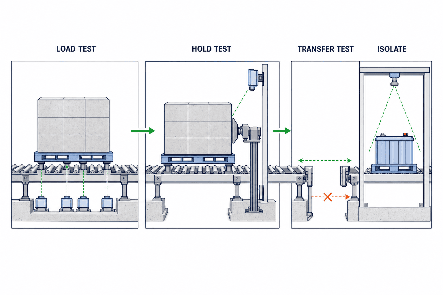
FAT verifies design and fabrication at the supplier. SAT verifies operation with the actual floor, power, network, adjacent machines, operators and procedures. FAT does not replace SAT, and neither stage replaces statutory inspection, risk assessment or functional-safety validation.
| Test | Input / condition | Example pass criterion | Required evidence |
|---|---|---|---|
| Maximum eccentric load | Maximum mass, worst CG, minimum supports | Deflection, temperature and current remain within design limits | Load certificate, readings, video |
| Transfer mismatch | Maximum allowed height/centreline error | No impact, snag or support loss | Survey, current/acceleration trend |
| Stopped-load retention | Maximum mass, minimum friction, power loss | Within permitted movement, no unintended restart | Displacement, state transition, PLC log |
| Sensor fault | Blocked, open circuit, contradictory signals | Upstream stops; no false entry | I/O, alarm and physical-position record |
| Double entry | Competing commands into one zone | One rejected; safe state retained | Command and rejection logs |
| Communications loss | PLC-to-PLC, MES and supervisory links interrupted separately | Defined local behaviour and reconciliation | Timeline, queue and reconciliation result |
| Emergency stop | Each speed, mass and position | Stop/retention established by risk assessment | Repeated stopping time/distance |
| Jam recovery | Bridged pallet, skew and drive failure | Approved recovery without unsafe improvisation | LOTO, video and elapsed time |
| Abnormal battery | Simulated temperature/leak/unknown ID | Transport inhibited, isolate, alarm, notify | Sensor, routing and notification record |
| Component change | Representative roller/motor/sensor | Replace with specified tools, staffing and time | Procedure deviation, time, restart check |
| Capacity run | Representative product mix | Agreed flow, failure rate and accumulation | Raw log, stop classification and formula |
Turn a number into an acceptance criterion
“20 units per hour” only says one unit every three minutes on average. If ten units arrive in a burst and the next station stops for 15 minutes, average rate cannot determine the required buffer. Use a transparent spreadsheet or discrete-event model with arrival distribution, downtime scenarios and recovery rate.
“99% availability” is also ambiguous unless planned stops, adjacent-equipment losses, recovery time, denominator and observation period are defined. If equipment-responsible stops total 12 minutes in an eight-hour test, the simple operating-time ratio is (480−12)÷480 = 97.5%. One eight-hour test does not prove long-term availability. Separate an initial capability run from the long-term warranty measurement.
Test the maximum condition without damaging the machine
If the real workpiece is unavailable at FAT, a load fixture may be used. Match not only total mass but centre of gravity, foot reactions, underside and stiffness. Water or steel-plate ballast can shift unless restrained, so its securing and lifting risks must be assessed. At SAT, use real workpieces and pallets where practical and record differences from the dummy.
Write standards into the RFP without overclaiming scope
One line saying “ISO compliant” leaves the scope, edition, responsibility and evidence undefined. Safer wording is specific:
- Use ISO 12100:2010 as a reference for a documented risk assessment covering intended use, reasonably foreseeable misuse and lifecycle hazards; reconfirm currency and applicable standards at contract.
- Consider ISO 14120:2015 as a general reference for selecting, designing and constructing fixed and movable guards, and require corresponding evidence. Do not treat it as a complete specification for interlocking devices, safety-related controls or machine-specific hazards; coordinate it with ISO 14119, ISO 13849 and locally adopted requirements as applicable.
- For safety-related control parts, apply an appropriate method such as ISO 13849-1:2023 and submit safety functions, PLr rationale, architecture, component data, calculations and verification/validation evidence.
- Apply the contractually specified edition of IEC 60204-1 together with locally adopted rules and plant standards to machine electrical equipment; submit test records and documentation.
- Where AGV/AMR is included, verify the edition and scope of ISO 3691-4 and assess the system including its operating zone; do not transfer it unconditionally to fixed conveyors.
ISO 12100:2010 was confirmed in 2022, but ISO lists a replacement draft under development. ISO 3691-4:2023 also has a successor draft. For a long project, state the contract baseline date, treatment of later revisions and responsibility for redesign cost.
Decision gates for implementation
Gate 1: Are inputs complete?
Make unknown workpiece mass, CG, support, volume, abnormal state, floor and interface data visible. Where a critical input is an assumption, assign an owner and due date.
Gate 2: Do local load and transfer work?
Check rollers, pallet, stop, frame and floor against the same load cases. Resolve transfer gaps and control ownership.
Gate 3: Are safety and recovery designed?
Review safety functions, guards, stopped-load retention, LOTO, recovery, battery abnormality, power loss and communications loss. Do not push engineered safety into procedures alone.
Gate 4: Has FAT passed with evidence?
Reproduce maximum/eccentric load, stopping, transfer, fault injection, jam recovery and maintenance. Close deviations and preserve raw data and instrument information, not video alone.
Gate 5: Has SAT passed in the actual environment?
Verify the floor, interfaces, network, operators, real workpieces and EHS procedures. A conditional acceptance needs an owner, compensating measure, deadline and retest date.
Gate 6: Can warranty values be measured after launch?
Collect stop reason, current, temperature, occupancy, jam, maintenance and damage data under the same definitions as the warranty formula. A guarantee that cannot be measured cannot be managed.
Common failures
- Quoting only by maximum kilograms: each bidder assumes different support and eccentricity.
- Using maximum speed as takt: acceleration, accumulation, transfer and process waiting are omitted.
- Treating motor-off as restraint: stopping, holding, locating and safe restraint are mixed.
- Checking the floor after fabrication: anchors collide with joints, reinforcement or pits.
- Excluding recovery from FAT: hazardous bypasses become routine on site.
- Sending abnormal batteries down the normal route: an isolation event blocks production and egress.
- Listing a standard number only: edition, scope, evidence and responsibility remain unclear.
- Accepting FAT video alone: load, instrument calibration, PLC log and deviations cannot be traced.
- Calling CAD whitespace maintenance access: removal paths, lifting gear and technician posture are absent.
FAQ: practical heavy-load conveyor automation
What percentage design margin should a heavy-load conveyor have?
There is no universal percentage. Evaluate dynamics, eccentricity, supports, transfer impact, material variation, fatigue and future workpieces separately. A preliminary “30% margin” can support early comparison, but it does not replace final structural and safety calculations.
For a 3,000 kg workpiece, is a roller conveyor or an AGV better?
A conveyor may fit a fixed, frequent flow needing repeatable positioning. AGV/AMR may fit routing changes and multiple destinations. Compare floor, traffic, docking, rescue, charging and transfer stability, not payload alone.
What should a battery plant decide first?
Define the product’s process state and abnormal response: energized/charge condition, retained energy, required temperature/smoke/leak detection, isolation destination and fire/EHS procedure. Select transport after those states are defined.
What if drawings are incomplete at RFP stage?
Create an assumption register. Record value, basis, impact, confirmation owner, due date and recalculation scope. If support points or CG remain unknown, separate budget quotation from a firm quotation.
Are FAT and SAT just the same tests repeated?
No. FAT checks the fabricated equipment and controls at the supplier. SAT checks integration with the actual floor, adjacent equipment, utilities, network, operators and EHS procedures. Some tests repeat; each stage also has unique conditions.
Is the catalogue “up to 3,000 kg” a safe operating load for my line?
It is a published family limit, not automatic approval of one configuration. The pallet, fixture, eccentricity, speed, transfer and environment need formal selection and risk assessment by the supplier/integrator and owner.
Could a Thailand project receive BOI incentives?
A BOI-origin first-half 2026 summary reported 132 applications worth approximately THB 17.2 billion under the Smart and Sustainable Industry initiative for machinery upgrades, digital technology, automation and robotics. This indicates investment activity, not eligibility of a particular conveyor. Confirm the latest activity scope, dates, investment thresholds, local-content conditions and application process with BOI or a qualified adviser.
Conclusion: accept the line because it can stop, retain and recover—not merely because it moves
For 3,000 kg-class heavy-load conveyor automation, catalogue payload is only the starting point. Build a load envelope including workpiece, pallet and fixture; verify centre of gravity and support reactions; design stopped-load retention, transfers, jam recovery, floor/foundation, maintainability and battery abnormal response as one system. The RFP fixes inputs and responsibilities. FAT/SAT must test not only normal continuous movement but eccentric loads, mismatch, power loss, sensor failure, communications loss, double entry, abnormal-product isolation and component replacement with auditable evidence.
TOMAS TECH can support Thailand factories from workpiece/support-point definition and vendor comparison through a heavy-load conveyor RFP, PLC/MES interfaces and FAT/SAT evidence planning. You can contact us while comparing concepts or before a maximum-payload figure has been translated into acceptance criteria.
References
- Bosch Rexroth, “Transfer system TS 7plus”: https://www.boschrexroth.com/en/de/products/industrial-solutions/assembly-technology/conveyor-and-transfer-systems/ts-7plus-transfer-system/
- Bosch Rexroth, “Bosch Rexroth announces next-generation conveyor capable of transporting heavy payloads up to 3000kg” (31 Mar 2026): https://www.boschrexroth.com/en/us/company/press/bosch-rexroth-announces-next-generation-conveyor-capable-of-transporting-heavy-payloads-up-to-3000kg-7872.html
- Bosch Rexroth, “Battery Production Solutions”: https://www.boschrexroth.com/en/at/industries/battery-production/
- Thailand BOI / OSOS, “Thailand Secures $43.6bn 1H 2026 Investment Surge…” (23 Jul 2026): https://osos.boi.go.th/EN/news/2430/Thailand-Secures-43-6bn-1H-2026-Investment-Surge-as-Big-Tec/
- ISO 12100:2010: https://www.iso.org/standard/51528.html
- ISO 14120:2015: https://www.iso.org/standard/59545.html
- ISO 13849-1:2023: https://www.iso.org/standard/73481.html
- IEC 60204-1:2016 + AMD1:2021: https://webstore.iec.ch/en/publication/26037
- ISO 3691-4:2023: https://www.iso.org/standard/83545.html
- Association for Advancing Automation (A3 / Automate.org), Bosch Rexroth Corporation, Battery Show 2026 exhibit announcement (11 Sep 2026): https://www.automate.org/motion-control/news/new-heavy-payload-conveyance-tightening-technology-and-innovative-controls-highlight-bosch-rexroths-booth-at-the-battery-show-2026
This article is a general design and procurement guide based on public information checked on 20 September 2026. It does not replace project structural calculations, functional-safety assessment, legal compliance, or fire/building engineering.


