


Tiny components pass unnoticed, transparent containers produce unstable signals, and a conventional sensor will not fit beside the conveyor. A fiber optic photoelectric sensor can solve such problems, but a small head alone is not a specification. The sensing method, fiber head, amplifier, response mode, mounting, wiring, and test conditions must work as a system. This guide helps procurement, engineering, and maintenance teams at Thai factories turn an application into a comparable quotation and an acceptance test.
A fiber optic sensor separates the electrical amplifier from the fiber that carries light to the detection point. This lets a compact head work in a constrained or harsh location while the amplifier remains accessible. It does not mean that every fiber is heat resistant, chemical resistant, or able to detect every clear material. Temperature rating, minimum bend radius, sensing distance, and amplifier compatibility depend on the exact part numbers and conditions. ifm’s technical overview describes the two-part architecture.
Our general photoelectric sensor selection guide compares sensing families. This article starts where that broad comparison ends: how to specify a fiber-based solution. For the wider machine and controls scope, read our FA system procurement guide.
Start with the detection decision, not a model number
Write down what object must be detected, at which physical point, and by what deadline. “Presence of a transparent bottle” is incomplete: is the container empty or filled, labelled or bare, tilted or upright? Is the intended decision bottle presence, cap presence, or fill level? Include the smallest, darkest, most reflective, and most transparent production variants, not only the sample that is easiest to obtain. Record line speed, changeovers, ambient light, cleaning agents, vibration, and access for maintenance.
Define the consequence of the output. Simple presence checking, positioning, counting, and jam detection tolerate different errors and delays. A missed count can corrupt production records even if a machine continues running. Include PLC input filtering, edge detection, and timers in the signal path. A catalog value for “minimum detectable object” is not a guarantee that the complete PLC system will count every object.
The minimum application package for a supplier contains workpiece dimensions, material, color, surface, transparency, detection direction, actual sensing distance, mounting envelope, heat and contamination, moving cable sections, control voltage and input type, required takt time, and cleaning interval. Without this package, a cheap sensor quote can trigger late bracket and wiring redesign.
Choose through-beam or reflective sensing from the workpiece and machine
Through-beam fiber units place emitter and receiver opposite each other and detect a change when an object interrupts the beam. They are a strong first candidate for small passing parts when both sides can be mounted. Even a transparent object needs testing because the signal change can be small. Reflective units send and receive from the same side, which helps where the opposite side is inaccessible. Their result depends more directly on target color, gloss, tilt, and background reflection.
Other heads may be needed for closely spaced pins, fine edges, glass, liquid levels, or transparent film. A narrow beam, slit, lens, coaxial arrangement, or application-specific head may suit a particular problem. A catalog phrase such as “clear-object detection” never establishes performance for every resin, thickness, radius, or background. OMRON’s E32 lineup publishes optical-axis size, bend radius, and sensing distance by head, amplifier, and operating mode. One headline distance cannot settle a purchase decision.

| Item | Through-beam | Reflective |
|---|---|---|
| Installation | Access on both sides | Usually one side |
| Typical task | Passage, small-object presence, positioning | Presence where opposite access is blocked |
| Main risks | Misalignment, dual-side wiring, dirt | Background, color, gloss, angle |
| Clear objects | Test actual interruption margin | Test return-light difference from background |
This is a comparison of principles, not a guarantee for any model. If a small bracket can be added to the far side, through-beam sensing may cost less over the machine’s life than repeated adjustment of a marginal reflective installation. Check access for cleaning and alignment with the guard closed.
Select the head in four passes
First, choose a tip geometry that fits. Threaded heads can be fixed reproducibly; cylindrical and flat heads fit other tight spaces. Check the complete assembly in CAD: nut, bracket, tool clearance, cable exit, and workpiece sweep. A head that fits by itself can still be impossible to install or replace.
Second, check optics using the exact amplifier and mode. Published sensing distances vary with fiber length, lens, target, and response setting. The E32 data show different distances for E3X-ZV and E3NX-FA amplifiers and for GIGA versus faster modes. Measure received-light separation between worst acceptable targets and the empty or rejected condition at the real distance. Check neighboring heads for mutual interference.
Third, match the environment. Heat, chemical cleaning, oil, condensation, dust, and vibration require part-specific head, sheath, and protection ratings. ifm lists particular fibers with a 1 mm minimum bend radius, up to one million bending cycles, and temperatures up to 290°C. These are specifications for the indicated product options, not universal fiber-sensor ratings. The installed combination must be checked on its own data sheet.
Fourth, design the cable route and length. Moving the amplifier to an accessible cabinet increases the fiber length and number of bends. Bending below the specified radius, twisting through a moving joint, or rubbing against sheet metal can reduce received light or break the fiber. Verify whether the model is field-cuttable, whether a dedicated cutter is required, and which replacement length can be obtained locally.
Select the amplifier for speed, light margin, control interface, and maintenance
An amplifier evaluates received light, sets a threshold, selects a response mode, and produces a control signal. Compare compatible heads, response time, light margin, NPN or PNP output, available IO-Link diagnostics, display, parameter backup, and replacement procedure. If the existing PLC expects an NPN signal, a PNP amplifier cannot simply be swapped in even when the optical head fits.
The fastest response setting is not automatically the best. Faster processing can trade away detection range or excess gain. ifm’s OCF mode guide gives product-specific examples: HIGH SPEED 25 µs, FAST 50 µs, STANDARD 250 µs, FINE 1,000 µs, POWER 4,000 µs, and HIGH POWER 12,500 µs. Those values belong to OCF; they illustrate why the response and light margin must be specified together. Panasonic’s FX-500 search page likewise lists H-SP at 25 µs or less, FAST at 60 µs or less, and STD at 250 µs or less for that series. Do not combine a catalog’s fastest response and greatest range unless the same head, mode, and target conditions support both.
A display showing received light can help maintenance compare clean, dirty, occupied, and empty states. If remote parameter access or IO-Link diagnostics is needed, include the master, wiring, PLC data points, and integration effort in the quotation. An amplifier feature on paper creates no operational value until it reaches the maintenance workflow.
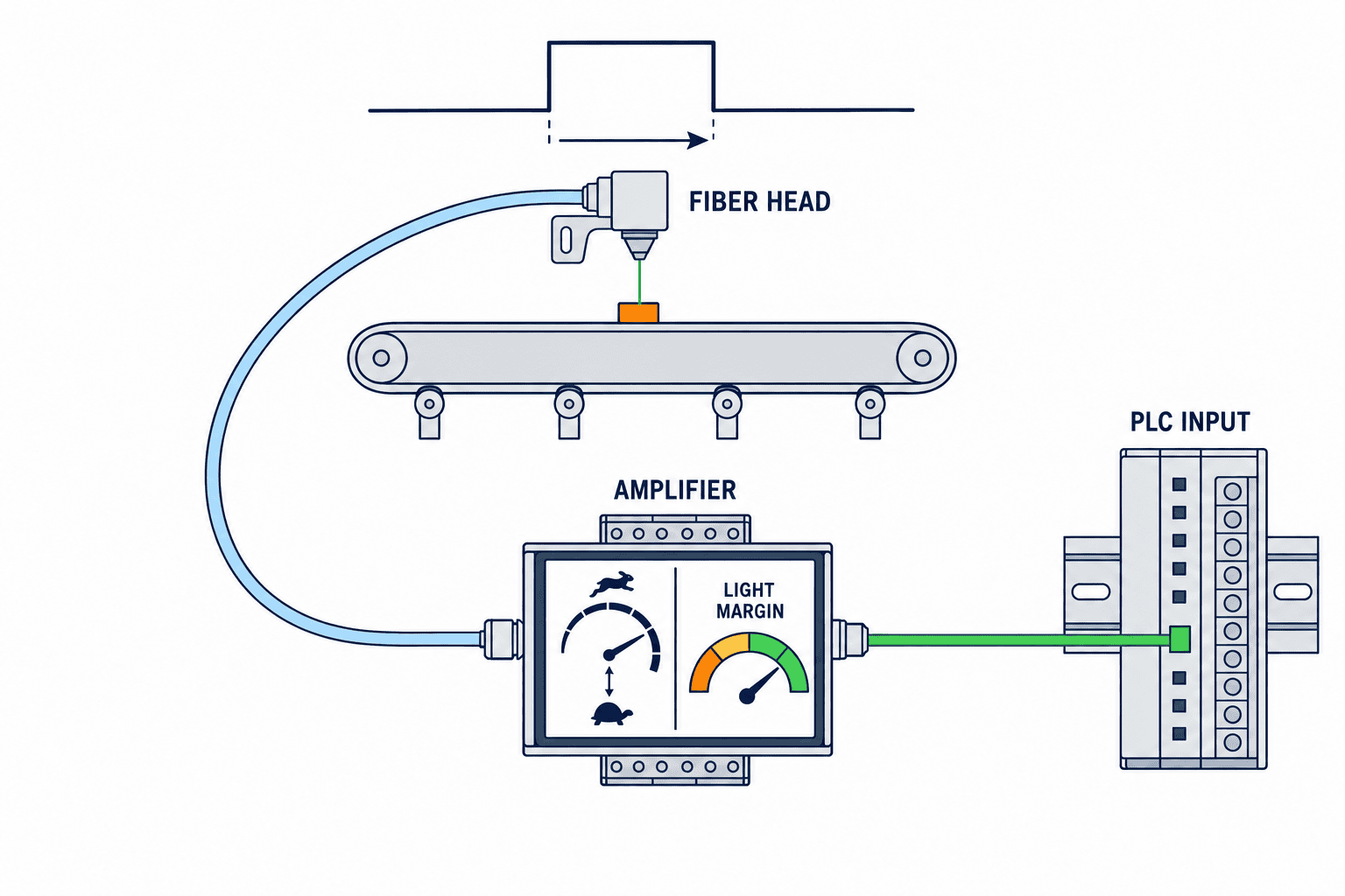
Calculate how long the target crosses the beam
Conveyor speed alone does not define the required response. Divide the smallest effective target width crossing the beam by travel speed to estimate the optical interruption time. For illustration, a 2 mm effective width at 1 m/s gives about 2 ms. This is a geometry example, not a performance guarantee: spot size, vibration, PLC scan, input filtering, and output holding time still matter. Measure the actual signal at the machine.
Counting also requires sufficient OFF time between parts. A sensor can detect each part yet the PLC may merge two consecutive pulses. A stop, reversal, or bounce may create a second count. Specify the edge logic, conveyor direction, encoder conditions, and restart behavior. Do not solve every short pulse by choosing the fastest amplifier mode; confirm that the resulting lower light margin still tolerates contamination.
Transparent targets need a real variability set. Labels, liquid, wall thickness, mold seams, droplets, and condensation alter transmission and reflection. Test empty and full containers, clear and tinted versions, dry and wet surfaces, and different production lots. The supplier’s application statement narrows candidates; the factory trial determines acceptance.
Make quotations comparable with a seven-column decision sheet
Use the columns “application and failure mode,” “head,” “amplifier and mode,” “mechanical mounting,” “electrical connection,” “verification,” and “spares and maintenance.” Ask each supplier for the paired head and amplifier part numbers, fiber length, output type, accessories, brackets, lead time, and replacement route in Thailand. A list of model numbers and prices cannot show whether the solution is fit for purpose.
| Purchase requirement | Evidence requested | Risk if omitted |
|---|---|---|
| Target and worst state | Samples, photos, sizes, surfaces, orientation | Demo sample passes but production fails |
| Method and geometry | Beam drawing, real distance, mounting surfaces | Bracket redesign at site |
| Head and amplifier | Exact pair, mode, compatibility, spare codes | Incompatible components |
| Controls | Supply, NPN/PNP, PLC input, filtering | Signal is lost or inverted |
| Environment | Temperature, chemicals, bending, cleaning | Early failure or declining light |
| Acceptance | Pass/reject samples, duration, recorded signal | Dispute over “detected” |
KEYENCE’s product overview lists through-beam, retro-reflective, diffuse reflective, high-flex, and environmental options. That range reinforces the need for an application-specific head and amplifier proposal. Compare total installed cost: mounting fabrication, cabinet space, wiring, setup, spare parts, and time to recover from a failure. An inexpensive head that needs difficult alignment after every replacement may cost more in downtime. A diagnostic amplifier that nobody monitors may add little value.
Preserve margin through mounting, teaching, and cleaning
Installation causes many field problems attributed to the sensor. Check bracket stiffness: a head on a long thin cantilever moves with vibration. Through-beam units need adjustment and a lockable final position. Reflective units require attention to glossy targets and angled backgrounds. Protect the head from accidental contact while leaving access for cleaning.
Do not teach from one convenient good sample. Record received-light readings for good targets, rejects, empty background, difficult variants, and a realistically dirty lens. Verify separation between distributions and threshold margin. A two-point teach procedure simplifies setup, but it does not test all product variation. ifm’s setup instructions describe registration with and without a target.
If received light gradually falls, inspect the optics, cable route, fasteners, and ambient light before repeatedly moving the threshold. Lowering the threshold can admit the background. Keep a photo of the mounted head, initial signal readings, selected mode, and settings so a replacement can restore the known good state.
Prove operation at FAT and SAT
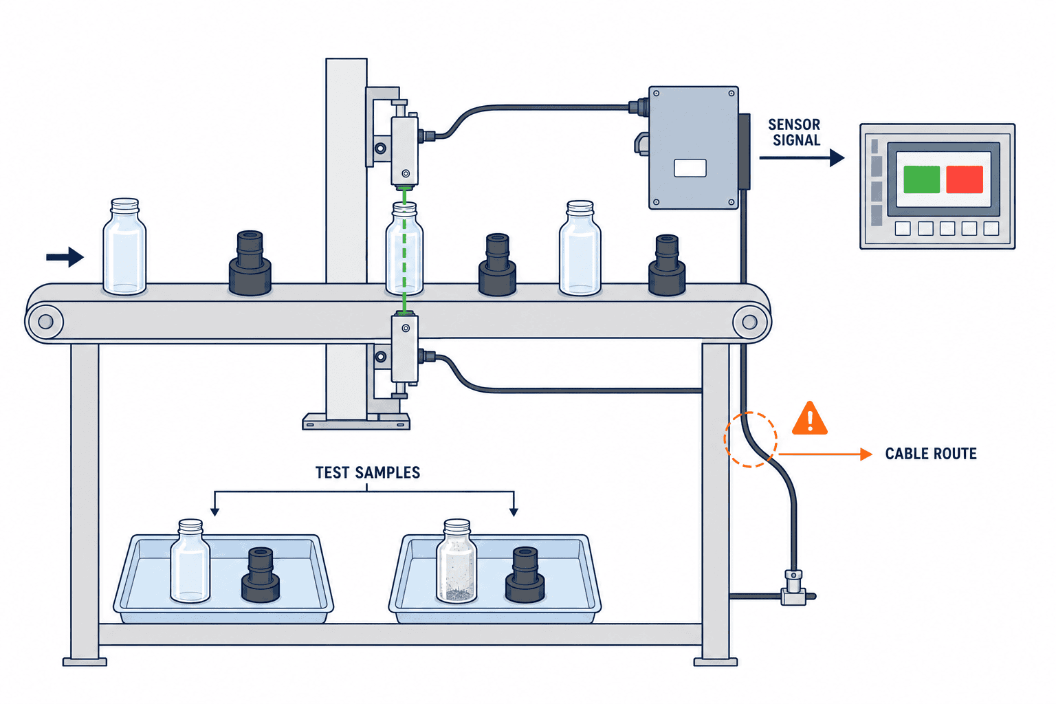
FAT checks what can be demonstrated at the machine builder; SAT checks the actual production workpieces, speeds, and environment at the factory. On both records identify workpiece type and lot, orientation, speed, amplifier mode, threshold, received-light reading, test duration, false positives, and misses. Agree pass criteria from the customer’s acceptable error rate and operating conditions. No single “thousands of cycles” number guarantees every sensor application.
At FAT, test every representative target, empty runs, backgrounds, and recipe changes. At SAT, add vibration, lighting changes, cleaning, longer runs, and nearby sensors operating together. At a Thai plant, verify that local maintenance can read the setting, source a replacement, and understand the panel instructions. If the amplifier output is correct but PLC counts fail, investigate input filtering, scan, and wiring before changing the optical method. If the amplifier reading fluctuates, investigate light distribution, background, interference, mounting, and cable first.
Three application examples
Counting small metal terminals: Measure the minimum terminal width and the minimum gap between terminals. If both sides are available, start with a narrow-beam through-beam head. Test ON and OFF durations at maximum speed. A vibrating terminal can cross the beam twice; separate optical detection from PLC counting results in the test record.
Checking transparent plastic containers from one side: Consider a reflective or clear-object application head, but test empty, filled, labelled, wet, and tilted containers across production lots. Metal and black backgrounds can produce very different return light. Presence of a container and presence of its contents are separate requirements.
Sensing near a hot process: The amplifier can often be placed outside the hot area, yet the head and sheath still need the appropriate rating. Check the temperature after the machine reaches steady state, contact with hot hardware, cable pull during door motion, and routing through protective conduit. Do not treat a standard head as equivalent to a dedicated heat-resistant model.
Avoid six recurring specification mistakes
Do not use the maximum catalog range as the installed design distance; it assumes a specified mode and target. Do not force the fiber around a bend tighter than its model’s rating. Do not choose speed without measuring the resulting light margin. Do not assume head-amplifier compatibility or PLC NPN/PNP compatibility from appearance. Do not approve transparent-object sensing using only one pristine sample. Finally, do not use an ordinary fiber optic photoelectric sensor as a personnel safety device. OMRON’s selection catalog explicitly warns against direct or indirect use to ensure people’s safety. Risk assessment and appropriate safety equipment belong in a separate safety design.
A repeatable procedure for measuring detection margin
Do not report only “detected” or “not detected” to the selection meeting. Read the amplifier’s received-light display under identical conditions. First, run the empty background repeatedly with a clean new head and record its variation. Then pass each product variant, production lot, and permitted orientation, noting the most difficult acceptable sample. Display scales are not necessarily comparable between brands: evaluate separation between good targets and the background within the same amplifier. Record the threshold and its distance from both populations in the test sheet.
Increase test difficulty one condition at a time: actual maximum line speed, day and night lighting, adjacent sensors operating, permitted workpiece tilt, and contamination representative of the end of the cleaning interval. Changing all conditions at once hides the cause of a failure. A transparent bottle can send light through a different curve or mold seam after a small position shift. If the worst case approaches the threshold, compare a new sensing method or mounting position before simply teaching the same installation again.
The readings also separate optics from controls. Stable amplifier readings and correct output LEDs with missing PLC counts point toward supply, grounding, NPN/PNP, input filtering, noise, or PLC scan. Overlapping light readings for targets and background cannot be fixed by PLC logic alone. Note the layer at which the separation disappears so the next shift does not repeat the same ineffective adjustment.
Attach a common condition sheet to every quotation request
The machine builder and sensor supplier must answer the same application statement. Give them one revision-controlled sheet with a process description, real workpiece photos, maximum speed, minimum spacing, detection-position drawing, nearby hardware, available mounting faces, temperature, cleaning chemicals, control I/O, and the consequence of an error. For a transparent target, specify resin, wall thickness, color, fill, label, and wetness in separate fields. Mark samples as prototype or production. If production variation has not yet been sampled, require a site re-evaluation in the purchase conditions.
Ask each proposer to name the recommended sensing method, the rejected alternative, and why. A reflective proposal should explain how it handles background variation and what light margin was measured. A through-beam proposal should show both mounting locations and how alignment and cleaning will be done. Require exact amplifier model, output type, response mode, setup procedure, and parameter restoration after replacement. Otherwise connectors, brackets, and backup amplifiers disappear from price comparisons.
Translate “works with real parts” into an agreed test: which samples, how many passes, what speed, lighting, distance, and recording method for false positives and misses? Name who may change the threshold and who must repeat testing of every product variant after a change. A common condition sheet makes later scope changes and responsibilities visible before an order is placed.
Design spare parts and the replacement procedure
Before acceptance, test whether maintenance can restore operation by replacing a failed component. Mark the original head position, remove it, install a replacement, restore amplifier settings, and test the most difficult workpiece as well as the empty state. Record tools, duration, and the person authorized to realign. On a multi-product line, success with one recipe does not complete recovery if other variants use different thresholds.
Decide whether to stock both amplifier and head from expected downtime loss, failure exposure, and local replenishment time. A similarly shaped warehouse part may have different optics or incompatible connections. If the fiber is field-cut, the technician needs the correct cutting and insertion method. Keep head orientation, beam alignment, bend route, installation photos, and settings under the machine identifier alongside the electrical drawing. A large difference from initial acceptance readings after replacement must be investigated before production restarts.
Plan tests separately for difficult workpieces
Black resin, mirror-finish metal, and transparent resin each fail differently. Black resin can return little light, so test the darkest production lot with a reflective method. Polished metal may give a very strong return in one orientation and a weak one in another; record the permitted angle range. Transparent resin depends on wall curve, seam, contents, and background. Instead of grouping all three as “hard to detect,” classify whether light disappears, target and background become indistinguishable, or readings spread too widely. Select a method and mounting angle to address the specific cause.
Workpiece orientation has a tolerance range. Conveyor tracking, guide clearance, and vibration move the target. Test left, right, high, low, and rotated extremes that the line permits, not only the center. At an extreme, the beam may cross a hole or notch instead of solid material. Moving the beam to a place that always intersects the intended feature is often more robust than raising sensitivity. Dimension that beam position on the drawing; re-evaluate it if the product guide changes.
The “background” can be a guard, metal frame, conveyor belt, neighboring product, or an operator’s hand. Opening a door can change it. A black mask, different angle, or through-beam layout can help, but any added mask must be cleanable and replaceable. Run the machine through all normal no-product states and record that the output stays correct.
Define the boundary between sensing and line control
A correct sensor ON/OFF signal does not prove the line stops, counts, and records correctly. Trace the signal through voltage at the PLC terminal, input response, program timers, HMI alarm name, and event sent to the production system. If one passage produces two production events, reversal or restart logic may be the cause rather than the light path. If the PLC receives the signal but HMI never identifies the head, maintenance cannot quickly locate the fault.
State who owns the head position, mounting bracket, amplifier setup, PLC input change, FAT/SAT records, and acceptance sign-off. This matters when the sensor distributor, machine builder, and system integrator differ. Agree on both the process-level pass criteria and component responsibilities before a marginal detection result becomes a dispute.
Use one small site trial before ordering every station
Choose one representative station and compare two candidate methods or models with the same production samples. Include difficult lots, no-product background, routine lighting, and conditions near the cleaning deadline. Compare detection performance, setup time, mounting space, measured margin, ease of cleaning, and repeatability after replacement. Important installation constraints appear only when a real technician fits the device on the machine; a desk comparison is not enough for a full-line order.
Write down the selection and rejection reasons. For example, “reflective mounting was cheaper but values for black parts overlapped the background, so through-beam was selected.” Future engineers then understand the decision when a new variant appears. Transfer residual limitations, such as a tilt that cannot be detected or a cleaning interval that cannot be extended, into operating instructions. Maintenance needs the conditions under which the chosen model works, not just its part number.
Keep the validated test record linked to machine ID, head and amplifier models, and parameter revision. A machine move or PLC software update can change outcomes without changing the sensor. Change control should review input filters and counting logic along with optics. Teach cleaners how to wipe the optical surface without moving the head and which display reading to check afterward.
Handover and next steps for a Thai factory
Before purchase, complete a trial using difficult real workpieces, verify the exact head-amplifier pairing, measure margin at operating speed, check PLC input compatibility, approve bracket and cleaning access, confirm bend protection and locally available spares, and sign off the FAT/SAT plan. When a product variant or speed changes later, repeat the affected tests. Archive amplifier mode, threshold, output logic, timers, interference settings, change date, and reason. A replacement that fits mechanically can still have different optical characteristics.
TOMAS TECH can assess the sensor position together with mechanical installation, PLC/HMI signal capture, and production and quality data recording. If your Thai line misses small parts, misreads transparent products, or cannot explain stops, send us sample details, a line video, mounting photos, and PLC input specifications via our contact page. We can begin with the test conditions for one process before making a purchase proposal.


