


More and more factories in Thailand are following up their rooftop solar installation with an industrial battery energy storage system, or BESS. Peak shaving, lower demand charges, keeping a line alive through an outage. As an investment case, it holds together well. What tends to go thin is the operating plan after commissioning. Two sentences usually close the discussion. “It has a BMS, so it is fine.” “The manufacturer must be watching it remotely.”
Thailand’s mandatory standard TIS 63056-2567, expected to take effect in September 2026, will not fill that gap. What a certificate guarantees is product safety at the moment of shipment, not the condition of the cells three years into service. This article sets out how to keep an industrial battery under continuous safety observation, in other words how to build a battery monitoring system, across five layers. Certification, BMS data, early warning signs, integration with the OT systems you already run, and cost and staffing. The subject here is the battery itself, not generation output and not incoming power quality.
What TIS 63056-2567 changes in Thailand, and what it does not
How the mandatory standard came about
On 23 June 2026, the industrial product standards committee of the Thai Industrial Standards Institute (TISI) approved the addition of five solar power system items to the list of products covered by mandatory standards. The five are photovoltaic cable (TIS 62930-2564), lithium batteries for electrical energy storage systems (TIS 63056-2567), low-voltage fuses for photovoltaic use (TIS 60269 Part 6-2567), inverters (TIS 2603 Part 2-2556) and DC circuit breakers (TIS 60947 Part 2). According to the Ministry of Industry, enforcement is expected during September 2026 following publication in the Royal Gazette. The standard for the photovoltaic module itself (TIS 61730 Part 2-2567) was designated as mandatory ahead of these and is scheduled to take effect around the same time.
The policy intent behind this is to slow the inflow of cheap equipment that does not meet the standards. Seen from the factory floor, it shows up as a practical change. Batteries procured from here on will be difficult to clear customs and difficult to install unless they are certified. Equipment already installed does not retroactively become illegal, but the requirement will bite whenever you expand or replace.
One caveat on the date. Publication in the Royal Gazette is still awaited. At the time of writing we could not confirm an officially published enforcement date, so treat September as an expectation rather than a settled fact.
What TIS 63056-2567 actually contains is type testing at the point of shipment
TIS 63056-2567 is based on the international standard IEC 63056:2020. That standard was published on 27 March 2020 and sets out safety requirements and test methods for secondary lithium cells and batteries used in electrical energy storage systems with a nominal DC voltage of up to 1,500V. Its scope covers photovoltaic systems, residential storage systems, grid-connected and off-grid large-scale storage, and uninterruptible power supplies (UPS). Portable systems of 500Wh or less are out of scope. The baseline safety requirements for industrial applications sit in IEC 62619, with IEC 63056 positioned as an additional set of requirements specific to energy storage systems.
This is where the argument of this article starts. According to the explanation published by the technical reference site Battery Design, what IEC 63056 specifies is design verification testing on representative samples, in other words type testing. Dielectric withstand against high voltage, high-altitude conditions, humidity and condensation, a thermal runaway propagation test that checks whether a single cell going into runaway can be contained, testing of the thermal management system, and functional tests confirming that the BMS protects against overvoltage, undervoltage, overcurrent and overtemperature. Every one of these confirms design validity. None of them requires continuous monitoring during operation.
Put differently, certification is a snapshot showing that the design fails safe as it leaves the factory. Air conditioning that drifts out of balance two years in, leaving one group of modules sitting at a higher temperature than the rest. Cell-to-cell voltage spread that widens by year five until specific cells are being run in a slightly overcharged state. Degradation that progresses as a function of time cannot, in principle, be caught by a type test.
There is a separate standard for the system side
For the system as a whole rather than the battery alone, there is IEC 62933-5-2. The 2025 edition addresses safety requirements for grid-integrated electrochemical energy storage systems, with a scope covering the whole BESS lifecycle from design through end-of-life management. In the world of international standards, in other words, product safety (IEC 63056) and system safety (IEC 62933-5-2) have clearly separated roles.
What Thailand has just made mandatory is the former, the product side. How the system side is operated remains squarely within the responsibility of whoever installs and whoever runs it. Missing this asymmetry leads straight to the false comfort of “we bought certified equipment, so the safety work is done.”
The root causes sit on the system side, not in the cells
There is data behind that point. In May 2024 the Electric Power Research Institute (EPRI) published a white paper analysing its BESS failure incident database. According to that paper, the failure rate of grid-scale BESS worldwide fell by 97% between 2018 and 2023. Safety is genuinely improving. Even so, the analysis of the 26 incidents where a root cause could be identified is instructive.
Only 3 incidents, 11% of the classified set, were attributed directly to the cell itself. The failing elements were dominated instead by BOS (Balance of System, meaning wiring, enclosures, power conversion equipment, cooling and fire suppression) and by controls (BMS, EMS, sensors and communications). In its conclusions the paper states plainly that the data contradicts the widely held assumption that lithium-ion cells are the leading cause of failure.
Further, among the incidents where the age of the system was known, 72% occurred during construction and commissioning or within the first two years of operation. Integration, assembly and installation was the single largest root cause category. In a cluster of 30 incidents from 2018 and 2019, of which 27 occurred in South Korea, investigation found that a substantial share had been sitting above the recommended upper state of charge immediately before the incident, specifically above 90% SOC. Deviation from operating conditions is itself counted among the causes.
The failure pattern called “the alarm was there”
One of the classified examples in the same white paper is the fire that occurred on 20 September 2022 at the Elkhorn battery storage facility in Moss Landing, California. A vent shield had been installed improperly, an umbrella valve came loose, and that opened a water ingress path into the enclosure. Water entering through it caused an electrical arc, and one unit went into thermal runaway.
What happened next is the part worth studying. The paper cites the failure to escalate an insulation degradation alarm to operators as an aggravating factor, and records that smoke and fire were reported to the fire service two days after the first insulation alarm was logged. It concludes that had the insulation degradation alarm been reported properly, the escalation of an initial fault into a fire consuming all units might have been prevented.
That is not a failure of technology so much as a failure in the design of monitoring and notification. The signal was there. Nobody acted. As a failure pattern that could be reproduced at a factory BESS, it does not get any clearer than this.
On incidents in Thailand and ASEAN
While preparing this article we searched public sources for a fire involving a BESS installed at a factory in Thailand and could not confirm any. Whether none has occurred or whether none has been reported, we cannot tell. We will not assert either way.
What we can say is that the absence of a visible case is not evidence of safety. The EPRI white paper itself notes that a cause could be identified for fewer than one third of the incidents it has captured, and that the industry’s limited transparency is a constraint on the analysis. For a Japanese-owned factory making a management decision, the practical question is not “we have not heard of it happening in Thailand” but “would we notice if an internationally documented failure pattern started running in our own equipment.”
Layer 1, getting the data the BMS already holds out to the factory side
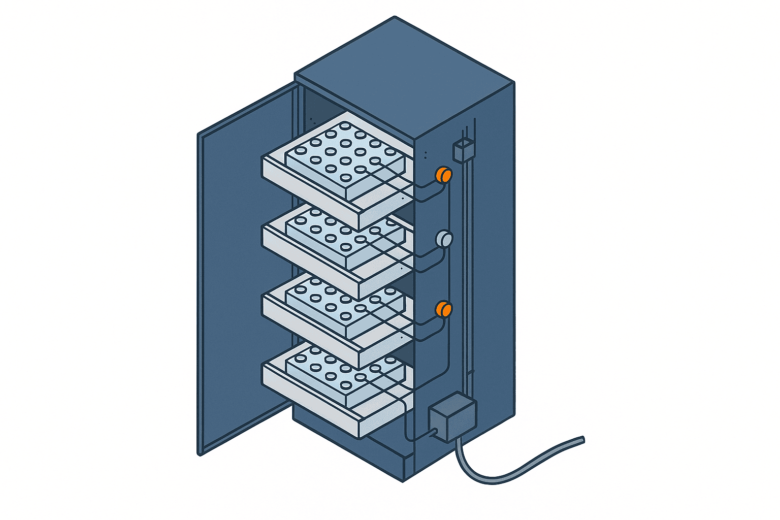
What a BMS is already measuring
Battery monitoring does not begin with buying new sensors. It begins with checking what the BMS already fitted is measuring, and which of those values never reach the factory side.
A 2025 review of German standards and regulations for battery management systems, published in Global Challenges (Tadoum and colleagues), groups the core functions of a BMS into five areas. Battery monitoring, safety, energy management, communication and data management, and thermal management. The parameters it lists as monitored are individual cell voltage, pack current, cell-level temperature, SOC (State of Charge), SOH (State of Health), internal resistance and insulation resistance.
Most of the data you need, in other words, is already being measured. The problem is that it stays inside the BMS and never becomes visible from the factory’s OT side. On many products, BMS data goes straight to the manufacturer’s cloud, or appears only on a local display panel. A screen nobody looks at overnight is functionally the same as no monitoring at all.
SOC and SOH are estimates, not measurements
One widely misunderstood point deserves attention here. SOC and SOH are not quantities that can be measured directly. They are values estimated by algorithms from measured quantities such as voltage, current and temperature.
What that means in practice is this. When the display reads 95% SOH, the definition behind that number and the accuracy with which it was computed vary by manufacturer. The Global Challenges review cited above points out that many existing standards stop at qualitative requirements and lack measurable benchmarks for important BMS functions such as state monitoring and energy management. It also raises, as concrete gaps, the fact that the definitions of SOC and SOH do not agree across standards, that no quantitative performance metric exists for estimation accuracy, and that specifications for sampling interval and response time in safety-critical situations are missing.
The consequence is that comparing an absolute SOH figure against another vendor’s product tells you nothing. What is usable is the change over time within one and the same unit. How fast is the SOH from a given BMS, on a given definition, falling. Managing that delta is the job that belongs to the factory.
The minimum data set to extract
As a realistic starting point, aim for a state where the following items flow regularly into the factory’s own monitoring platform. The acquisition interval varies by item.
| Data item | Granularity | Suggested interval | Main purpose |
|---|---|---|---|
| Cell voltage | Per cell, or min, max and average | 1 minute | Watching cell-to-cell spread |
| Cell temperature | Per module or finer | 1 minute | Temperature difference and rate of rise |
| Charge and discharge current | Per string | 1 minute | Detecting deviation from operating conditions |
| SOC | Per pack | 5 minutes | Totalling time spent at high SOC |
| SOH | Per pack | 1 day | Trending the rate of degradation |
| Internal resistance | Per module | 1 day | Separating poor contact from cell degradation |
| Insulation resistance | Per system | 1 minute | Detecting water ingress, condensation, damaged insulation |
| BMS alarms and events | All of them | On occurrence | Subject to escalation |
The last row matters most. What the Elkhorn incident demonstrated is that the outcome turns less on the values themselves than on who the alarm reached. Building a path that carries every event the BMS emits to the factory side, with nothing dropped, is the real goal of Layer 1.
Checking the communication interface
On the implementation side, the first thing to establish is what communication interface the BMS or the PCS (Power Conversion System) provides. Industrial BESS products commonly offer Modbus TCP or Modbus RTU, and some carry CAN or SNMP. Some products expose data only through a vendor cloud API, which brings constraints on acquisition interval and often an additional fee.
Run the contractual check in parallel. Depending on the warranty terms, connecting external equipment to the BMS communication port can by itself void warranty cover. In most cases a read-only connection raises no issue, but it is safer to confirm this with the manufacturer in writing beforehand.
Visualising generation output on the solar side and the operating condition of the PCS is a separate question, and we cover it in our article on monitoring rooftop solar generation at a factory. This article picks up from there and stays with the condition of the battery itself.
Layer 2, defining what an early warning sign is
Thermal runaway progresses in stages
What battery monitoring ultimately exists to avoid is thermal runaway. Thermal runaway is not an instantaneous event, though. It advances in stages, as a chain of chemical reactions that follow temperature.
A 2025 review of gas detection technology for thermal runaway in lithium-ion batteries, published in Frontiers in Physics (Qian and colleagues), organises the process as follows. First, in the range of 70 to 90 degrees Celsius, the SEI film decomposes, releasing carbon dioxide and ethylene. Between 90 and 170 degrees Celsius, reactions between the anode and the electrolyte generate short-chain hydrocarbons such as methane, propylene and ethane. Around 170 degrees Celsius, decomposition of the cathode and the electrolyte begins, releasing oxygen and a large quantity of heat. As the temperature climbs further, carbon monoxide, carbon dioxide, phosphorus pentafluoride and hydrogen fluoride are produced, and in the final stage reactions between the electrode and the binder release hydrogen. Across the body of literature, carbon dioxide is mentioned with a frequency of 90.5% and carbon monoxide 85.7%.
The important part is that the first reaction begins in the low 70s. At that stage nothing has changed on the outside and there is no smoke. Inside, however, decomposition reactions have unmistakably started.
Temperature and voltage alone are too slow
The same review notes that monitoring by temperature signal carries a time lag and a measurement error arising from heat conduction between the interior and the exterior of the cell. By the time a temperature sensor attached to the surface responds, the inside of the cell is already hotter than that.
On electrical signals, it observes that while they are directly tied to intrinsic battery characteristics, their immediacy and reliability are limited in large-scale storage systems. In practical terms, a sharp voltage drop does not appear until thermal runaway is already well advanced.
None of this is a reason to stop monitoring. Voltage and temperature from the BMS cost essentially nothing to acquire and are more than adequate for managing degradation trends. What it does require is a clear-headed positioning. Do not expect these two signals to be the sole mechanism that stops an event immediately before a fire.
Gas detection as an option
To catch the process earlier, there is the option of detecting the trace gases, the off-gas, that a battery releases. A 2025 review in Frontiers in Chemistry on the detection of early-stage thermal runaway gases using semiconductor sensors (Teng and Lv) states that gas signatures appear earlier than anomalies in voltage, current or temperature. Concrete examples it gives include the release of hydrogen ahead of carbon monoxide and carbon dioxide under overcharge conditions in lithium iron phosphate (LFP) cells, a hydrogen sensor that detected a hydrogen leak 67.79 seconds before the cell swelled, and a sensor targeting dimethyl carbonate that demonstrated more than 15 minutes of advance warning capability on LFP cells.
An explanatory article in the fire safety trade publication International Fire and Safety Journal makes similar points. It notes that Annex G of NFPA 855 explicitly acknowledges the limitations of using lower explosive limit (LEL) sensors and battery voltage monitoring as thermal runaway safety devices, that cell-level detection near or inside the module is regarded as the most reliable pre-runaway warning, and that under some conditions this yields up to 30 minutes of intervention time. The same article cites UL 2075 as the standard for gas and vapour detectors and FM Approvals 6540 as the approval for off-gas detectors.
Thirty minutes is enough to stop charging, run the ventilation, evacuate people and call the fire service. It is, however, an additional investment. Whether you fit it to every cabinet or only to higher-risk zones is a decision to take together with the cost discussion further below.
Ordering the monitoring indicators by how early they warn
Bringing the above together as a list of indicators a factory can actually watch gives the following. The timing column is an approximation drawn from published literature and field experience, and it varies considerably with equipment configuration and environment.
| Indicator | Main source | Condition it reveals | Approximate warning time |
|---|---|---|---|
| Cell-to-cell voltage spread | BMS | Loss of cell balance, widening capacity spread | Months to years ahead |
| Rate of SOH decline | BMS | One module degrading ahead of the others | Months ahead |
| Rising internal resistance | BMS | Poor contact, cell degradation | Weeks to months ahead |
| Time spent at high SOC | BMS | Deviation from operating conditions | Weeks to months ahead |
| Temperature difference between modules | BMS, added temperature sensors | Uneven cooling, localised heating | Days to weeks ahead |
| Falling insulation resistance | BMS, insulation monitoring device | Water ingress, condensation, damaged insulation | Hours to days ahead |
| Rate of temperature rise | BMS, added temperature sensors | Thermal runaway in progress | Minutes ahead |
| Off-gas such as hydrogen | Dedicated gas sensor | Decomposition reactions inside the cell | Minutes to tens of minutes ahead |
| Smoke, flame | Fire detection system | The event itself | After the event |
The top half and the bottom half of that table mean entirely different things. The top half is a maintenance planning conversation. The bottom half is an evacuation and first-response conversation. Mix them into a single dashboard and neither will work. That is precisely why the layers need to be designed separately.
Note also that monitoring voltage fluctuation and harmonics at the incoming supply point is different in purpose and different in installation location from monitoring cell voltage in a battery. The two are easy to confuse, so for the supply side see our separate article on incoming power quality monitoring.
Design thresholds in three levels
Once the indicators are settled, cut the thresholds into levels. In practice the following three-level structure is the easiest to work with.
- Advisory level. Recorded as a trend and handled at the monthly review. Notification goes to the responsible engineer by email only.
- Warning level. On-site check to be carried out the same day. Immediate notification to maintenance and to the engineering manager.
- Stop level. Charging and discharging halted, and disconnection from the grid if required. Notification to the duty shift and to management, including nights and holidays.
Take cell-to-cell voltage spread as an example. Advisory level is the point at which the difference between the highest and lowest cell voltage within a module begins to sit persistently above the normal operating range. Warning level is the point at which that difference shows a widening trend. Stop level is the point at which it approaches the BMS protection threshold. Because the specific values depend on the battery chemistry and the product specification, the realistic approach is to start from the manufacturer’s recommended values and tune them against your own operating record.
Layer 3, putting it on the OT systems the factory already runs

Do not add one more screen
This is the layer where projects most often stumble. Create a dedicated BESS monitoring screen and nobody will look at it. The factory already has a production management screen, an equipment availability screen and an electricity screen. Adding a fourth does not add a fourth pair of eyes.
The right move is to ride on the notification paths that already reach people. At Japanese-owned factories in Thailand, those paths broadly reduce to three.
- Andon and shop-floor indicator lights. Andon is the signalling system Japanese plants use to raise line abnormalities visibly on the floor. Put stop-level alarms on the same display system as existing line faults. It is the only path where the floor can react instantly.
- The existing IoT monitoring platform or SCADA dashboard. Show conditions up to warning level in the same place as the electricity and equipment screens. The requirement is that it be mixed into a screen people already look at daily.
- Notification to smartphone or email. Reaching the duty shift and management at night and on holidays. This is the one path to make redundant.
All three should be fed from the same event source, changing only the recipients and the conditions. Build separate decision logic per path and the three will fall out of agreement somewhere, without fail.
Document the escalation path
What the Elkhorn incident forces on us is the obvious fact that an alarm means nothing unless a person moves. Carrying equal weight with the technical integration, the following need to be written down on paper.
- Who takes first receipt of an alarm at each level. Defined by role, not by personal name.
- Who it escalates to if first receipt does not respond within a set time.
- Whether people may approach the equipment when a stop-level alarm fires, or should move away from it.
- Who contacts the fire service and the industrial estate management office, and at what stage.
- How the arrangement changes at night, at weekends and on Thai public holidays.
Battery fires are difficult to extinguish, and a fire that appears knocked down by water can reignite. The general factory instinct of “go and take a look first” may therefore not be appropriate for this equipment. Agree this point with the fire service and the equipment manufacturer in advance, without exception, and state it explicitly in the procedure.
The commissioning period is the most dangerous
The EPRI figure that 72% of failures with a known system age occurred during construction and commissioning or within two years of operation has a direct bearing on when monitoring should be brought up. The white paper points out that some failures occurred during the commissioning phase, when monitoring and communications were not yet running, allowing a leak or an insulation fault to develop into a large fire.
Sequencing the monitoring system as something to install “once the BESS is running stably” is therefore a choice to leave the highest-risk period deliberately unprotected. At a minimum, insulation resistance, temperature and BMS alarms, those three, should be reaching the factory side before commissioning begins.
What EPRI recommends for the operating phase
The same white paper organises recommended measures by root cause category. For failures caused by operation, it recommends battery monitoring and analytics that supplement the action of the BMS, generating trends and predictive analysis to identify potential failures early. For failures caused by design, it likewise recommends robust sensing and monitoring to give early warning of design defects.
An independent research institute, in other words, has arrived at the same direction. Put a factory-side analytics layer on top of the BMS.
Layer 4, cost and staffing

Indicative costs
The figures below are TOMAS TECH’s own internal estimate for building a comparable configuration at a factory in Thailand. They are not published market prices and they are not survey figures from a cited source. They move considerably with the size of the installation, the number of cabinets, whether a monitoring platform already exists and the communication specification of the BMS.
| Stage | Content | Indicative cost range |
|---|---|---|
| Preliminary survey | Confirming BMS communication specification, inventory of extractable data items, site survey | 50,000 to 150,000 THB |
| Layer 1 | Installing the data collection gateway and ingesting into the existing platform (per panel) | 150,000 to 400,000 THB |
| Layer 2 | Designing early-warning logic and thresholds, building the monitoring screens | 200,000 to 500,000 THB |
| Additional sensors | Added per-module temperature and per-cabinet gas detection (per cabinet) | 80,000 to 250,000 THB |
| Integration | Linking to andon, the existing IoT platform and smartphone notification | 100,000 to 300,000 THB |
| Operation | Server or cloud upkeep, threshold review, monthly review (annual) | 60,000 to 180,000 THB |
The ranges are wide because the volume of implementation work depends on how much existing infrastructure can be reused. If the factory already has an IoT monitoring platform and the BMS exposes data over Modbus TCP, Layers 1 and 3 land near the lower bound. If the BMS only publishes to a vendor cloud and a monitoring platform has to be built from scratch, you are at the upper bound.
Phase it in
There is no need to do everything at once. As a matter of priority, the rational sequence is to complete Layer 1 first, meaning extraction of BMS data and forwarding of alarms, accumulate three to six months of trend data on that basis, and only then set the Layer 2 thresholds against your own data. Drop another company’s recommended values in as they are and you get one of two outcomes. Either so many false alarms that nobody looks any more, or settings so loose that nothing ever fires.
Adding gas detection can wait until Layers 1 and 2 are turning. As noted above, though, insulation resistance and temperature monitoring are the exception and should be up and running before commissioning.
Staffing
The headcount required is smaller than people assume. Day-to-day monitoring is automated, and people are involved in only three situations.
- The on-site check when a warning-level alarm fires. Handled by the maintenance engineer.
- The monthly trend review. Around 30 minutes to look at the rate of SOH decline and the movement in cell-to-cell spread. Two people, one from engineering and one from maintenance, is enough.
- The annual threshold review. Verifying false alarms and missed events against a year of data and adjusting the levels.
A structure that assigns a new dedicated person purely for the battery does not survive contact with reality. The realistic form is to add one agenda item to the existing monthly equipment maintenance meeting.
How to read the Thai market situation
According to an analysis published by the trade publication Energy-Storage.news in March 2026, the draft of Thailand’s power development plan PDP 2024 sets targets of 10GW/10.5GWh of operational battery storage and 3.5GW of pumped hydro by 2037. The same article also points out that a large share of projects still do not stack up economically once storage is added.
There are two implications for factories. One is that the number of battery installations in the country will certainly grow over the next several years, and the experience level of the contractors doing the installation and maintenance will vary. The other is that precisely because the economics are tight, there is pressure to cut initial cost, and monitoring and safety systems are the items most likely to be cut first. Set against the EPRI white paper’s finding that integration, assembly and installation is the largest single root cause category, those two tendencies point at risk in the same direction.
Frequently asked questions
How much does a battery monitoring system cost
As shown in the cost table above, Layers 1 and 3 together come to roughly 250,000 to 700,000 THB where an existing monitoring platform can be reused, and a full configuration including gas detection can exceed 1,000,000 THB. Both are TOMAS TECH’s own internal estimates, and an actual quotation follows a site survey. As a way of framing the decision, expressed as a ratio to the capital cost of the BESS itself the figure usually lands within a few percent, which makes it straightforward to present as insurance-type spending to protect the asset.
We already have a BMS, so why do we need a separate monitoring system
The role of the BMS is to take protective action once a dangerous state has been entered. That function is essential in itself, but by the time protection operates, the abnormality has already happened. What the factory wants is the stage before that, the signs of degradation that develop over weeks and months, and those only become visible once BMS internal data is accumulated as a time series. The EPRI white paper likewise recommends, as a measure for the operating phase, monitoring and analytics that supplement the action of the BMS in order to identify potential failures early. Understand it as a layer sitting on top of the BMS, not as a replacement for it.
How far in advance can thermal runaway be detected
It varies greatly with the detection method. Within the published literature, methods relying on sudden voltage change or a rise in surface temperature respond only in the fairly late stages of thermal runaway, and temperature sensors are noted to carry a time lag arising from heat conduction. For gas detection, more than 15 minutes of advance warning has been reported for a sensor targeting dimethyl carbonate, and an industry commentary states that up to around 30 minutes of intervention time can be obtained depending on the implementation. These are values obtained under test conditions, however, and there is no guarantee that the same margin will be available in a real cabinet. The safe design assumption is a margin measured in minutes when building the first-response procedure.
If we choose equipment certified to TIS 63056-2567, are we protected from fire
Certification is a necessary condition, not a sufficient one. IEC 63056:2020, on which TIS 63056-2567 is based, is design verification testing on representative samples and does not call for condition monitoring during operation. In the EPRI analysis, among the incidents where a root cause could be identified, those attributable directly to the cell accounted for only 11%, with BOS and controls making up the majority. On top of choosing certified equipment, you need to build installation quality verification and post-commissioning continuous monitoring as separate pieces of work.
Can this be retrofitted to an existing BESS
In most cases yes. If the BMS has a read-only communication port, Layer 1 comes together by adding a gateway alone. Adding temperature sensors or gas sensors involves physical modification of the cabinet, so check the manufacturer’s warranty terms in advance. For existing installations, the reliable procedure is to begin with a preliminary survey establishing what can actually be extracted from the BMS as it stands.
Summary
Thailand’s TIS 63056-2567 is a welcome regulation in the sense that it slows the inflow of poor-quality batteries. What it guarantees, however, is product safety at the point of shipment. It does not catch degradation that develops over years in a factory, nor defects built in at installation. As the EPRI analysis shows, the leading causes of incidents lie on the system side rather than in the cells, and most of them surface between construction and commissioning and the second year of operation.
That is exactly why a battery monitoring system has to be thought about in layers. Layer 1 gets the data the BMS already holds out to the factory side. Layer 2 defines degradation trends and thermal runaway warning signs as indicators. Layer 3 puts those on the andon and the monitoring platform you already have, and settles who moves and when. Only with all three in place does the gap the standard leaves open get filled. And the cheapest place to start is Layer 1, because all it does is bring data that is already being measured to somewhere it can be seen.
Which data your own battery can expose, and how far it can be carried onto your existing monitoring platform, cannot be decided without looking at the communication specification of the equipment and the configuration on your site. TOMAS TECH has worked on both production equipment and factory systems for Japanese manufacturers here in Thailand. Even if you are not at the point of committing to an installation, and would simply like help taking stock of the current situation or structuring how to approach the question, you are very welcome to get in touch through our contact page.
References
- Warawut adds 5 solar cell products to the controlled goods list, TIS mandatory from September 2026, Krungthep Turakij
- Ministry of Industry designates additional solar cell system products as controlled goods, Daily News
- IEC 63056:2020 Secondary cells and batteries containing alkaline or other non-acid electrolytes – Safety requirements for secondary lithium cells and batteries for use in electrical energy storage systems, IEC Webstore
- IEC 62933-5-2:2025 Electrical energy storage systems – Part 5-2 Safety requirements for grid-integrated EES systems – Electrochemical-based systems, IEC Webstore
- IEC 63056, Battery Design
- Insights from EPRI’s Battery Energy Storage Systems (BESS) Failure Incident Database – Analysis of Failure Root Cause, EPRI White Paper, May 2024
- Qian Y. et al., Gas detection technology for thermal runaway of lithium-ion batteries, Frontiers in Physics, 2025
- Teng Z., Lv C., Detection toward early-stage thermal runaway gases of Li-ion battery by semiconductor sensor, Frontiers in Chemistry, 2025
- Tadoum D. D. et al., Standards and Regulations for Battery Management Systems in Germany – Review and Improvement Potentials, Global Challenges, 2025
- Li-ion BESS fire safety standards – how off-gas detection is reshaping battery safety regulations, International Fire and Safety Journal
- Thailand’s energy storage market lags despite renewable push and upstream manufacturing support, Energy-Storage.news


