


Choosing a wire and terminal block does not finish the connection design. A ferrule that fits the wire before crimping may no longer fit the terminal afterward. A plastic collar may stop full insertion. A connection that passes a momentary continuity check may still have a damaged conductor or an incompletely clamped ferrule. For a new or modified control panel in Thailand, specify and verify the wire, ferrule, crimping tool and receiving terminal as one approved combination. This guide turns that combination into procurement requirements, shop instructions, FAT evidence and SAT checks.
The subject here is wire end ferrules and their workmanship. For the wider electrical design and supplier scope, see our control panel design guide and control panel manufacturing guide. Those guides cover circuit, thermal, safety and handover decisions. The present article focuses on the last centimetres of fine-stranded conductors and the evidence needed to accept them.
Why “use ferrules” is not a complete specification
A ferrule gathers fine strands in a metal sleeve and is crimped before insertion into a connection point. It can make handling and repeatability easier, but adds metal and sometimes a plastic collar around the conductor. WAGO’s official guidance says ferrule use cannot receive blanket approval: the strip length, increased diameter, collar interference, crimp quality and insertion orientation must be checked for the connector. The maximum conductor size stated for an untreated conductor is not automatically the maximum with a ferrule.
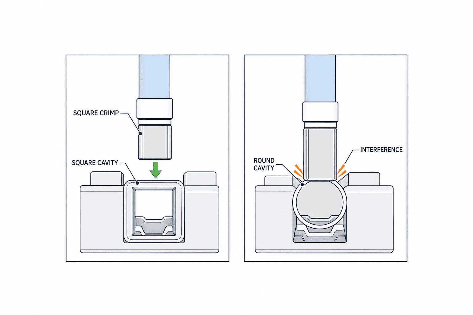
Phoenix Contact warns that a square crimp may not fit a round clamping space even when the nominal conductor cross-section is the same. Weidmüller distinguishes square crimping for square connection compartments and hexagonal crimping for circular ones. Neither geometry is universally superior. The correct choice depends on the exact receiving terminal, the tool and the resulting shape. A general terminal-block habit must not be carried over untested to a PLC plug, drive control terminal, safety device or compact connector.
Not every conductor needs a ferrule. Some terminals accept an untreated fine-stranded conductor; some connectors specify a different terminal treatment. Follow the device maker’s installation instructions and any applicable customer requirements. If a substitute is proposed, obtain evidence for the actual part numbers rather than relying on the name of a standard or a supplier’s statement that the parts are “equivalent.”
Build a connection-level compatibility table
Start with a wire schedule: wire part number, conductor material and stranding class, nominal cross-section, insulation diameter, function, destination and who will terminate it. Include shop wiring and field wiring. For an existing-panel retrofit, verify the markings and the actual cable specification rather than trusting an old drawing alone. Keep unusual heat-resistant wire, very fine conductors and aluminium conductors separate until the manufacturer explicitly confirms compatibility.
Then list every connection point: rail terminal, PLC connector, power supply, breaker, relay, drive, sensor amplifier and field device. Capture the maker’s conductor rules, ferrule permissions, strip length and tightening or clamp method for each part number. Where one panel contains several terminal families, give each point its own permitted preparation. A common ferrule for the entire cabinet is attractive administratively, but can conceal one incompatible device.
| Item | Information to approve | Check on the real sample |
|---|---|---|
| Wire | Part number, material, stranding, cross-section, insulation diameter | Marking and strand condition |
| Ferrule | Part number, single or twin, insulated or uninsulated, sleeve length | Strand fit, collar clearance and exposed metal |
| Tool | Maker, model, die or setting, service condition | Completed crimp and resulting profile |
| Terminal | Maker, part number, wire rules and strip length | Full insertion and correct clamping |
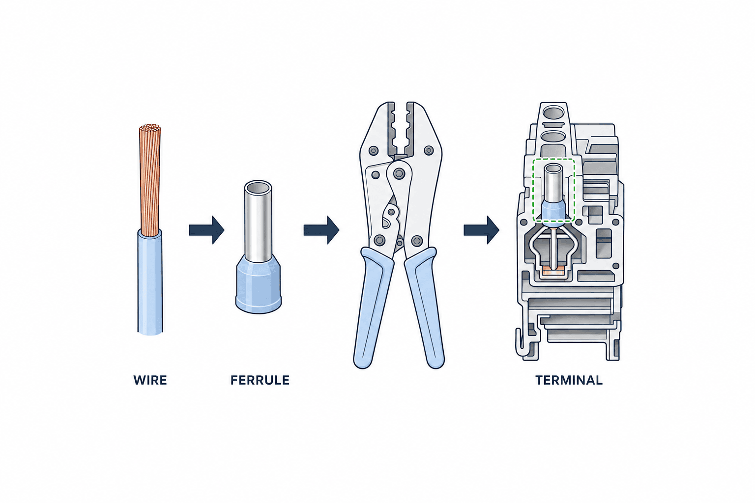
The approval unit is the combination of all four items, not a colour or a nominal size. Plastic collar colours can follow different coding systems and do not prove sleeve length, inside diameter, terminal clearance or a jointly approved tool combination. A purchasing substitution should compare dimensions and application evidence, then be demonstrated on the receiving terminal. Keep the wire schedule, terminal schedule, bill of materials and inspection instruction under the same revision.
Size the sleeve, collar and strip length together
The conductor cross-section is only the first filter. Check that the wire strands fit the barrel; that the metal sleeve length suits the terminal’s specified stripped length and contact area; and that the collar fits at the entrance without preventing complete insertion. WAGO points out that adding a ferrule increases the diameter and can reduce the maximum cross-section accepted by a connector. The permitted range may differ between insulated and uninsulated ferrules.
A longer sleeve does not automatically improve contact. A sleeve that projects too far may leave conductive metal exposed; one that is too short may not achieve the specified contact. Put the ferrule dimensions, stripping instructions and terminal insertion depth side by side. If the terminal maker requires a particular sleeve length or orientation, use that part-specific instruction. Twin ferrules require two separate permissions: the ferrule must be sized for the two conductors and the terminal must allow that connection. The existence of a twin ferrule does not authorize any two-wire connection.
For field wires whose final terminal has not been decided, do not crimp all ends merely to make the panel look complete. Specify the field termination as a SAT activity, protect the cable end and allow rework length. Label which wires are completed at FAT and which must be cut and terminated on site. This boundary prevents an installer from trimming an unsuitable sleeve without updating the drawings.
Match square or hex crimping to the terminal
Square, hexagonal, trapezoidal and other profiles change the outside shape and how it meets the clamp. Weidmüller describes square as suitable for square connection spaces and hexagonal as suitable for circular spaces. Phoenix Contact provides the practical warning that equal nominal cross-section does not guarantee a square crimp will enter a round space. Trial-fit a crimped sample into the chosen terminal. Observe the insertion direction, depth, friction, collar and final clamping action.
For certain WAGO connections, the official advice calls for orienting the crimp surface parallel to the contact surface. This is a device-specific instruction, not a universal direction for all brands. Put a photo or diagram of the approved insertion orientation in the work instruction. If a worker must bend or twist a wire sharply to fit the ferrule, recheck the terminal arrangement or crimp choice rather than using force.
A self-adjusting tool still has an application range. Confirm the exact wire and ferrule sizes, die, completed ratchet stroke and tool condition. If the supplier claims a product and tool combination is certified, check which exact models and scope the certificate covers. Record tool identity and inspection status. Approve first pieces separately when manual tools and automatic stripping/crimping equipment are both used.
Fix the production sequence and acceptance evidence
Cut the cable squarely without crushing strands, strip it to the approved length without nicking the conductor, insert all strands into the sleeve and crimp at the specified location. Weidmüller’s technical information stresses clean cutting, suitable stripping and complete conductor insertion. Do not treat a partially closed ratchet or a damaged ferrule as a product to be re-crimped and shipped. Cut back and make a fresh termination using the approved instruction.
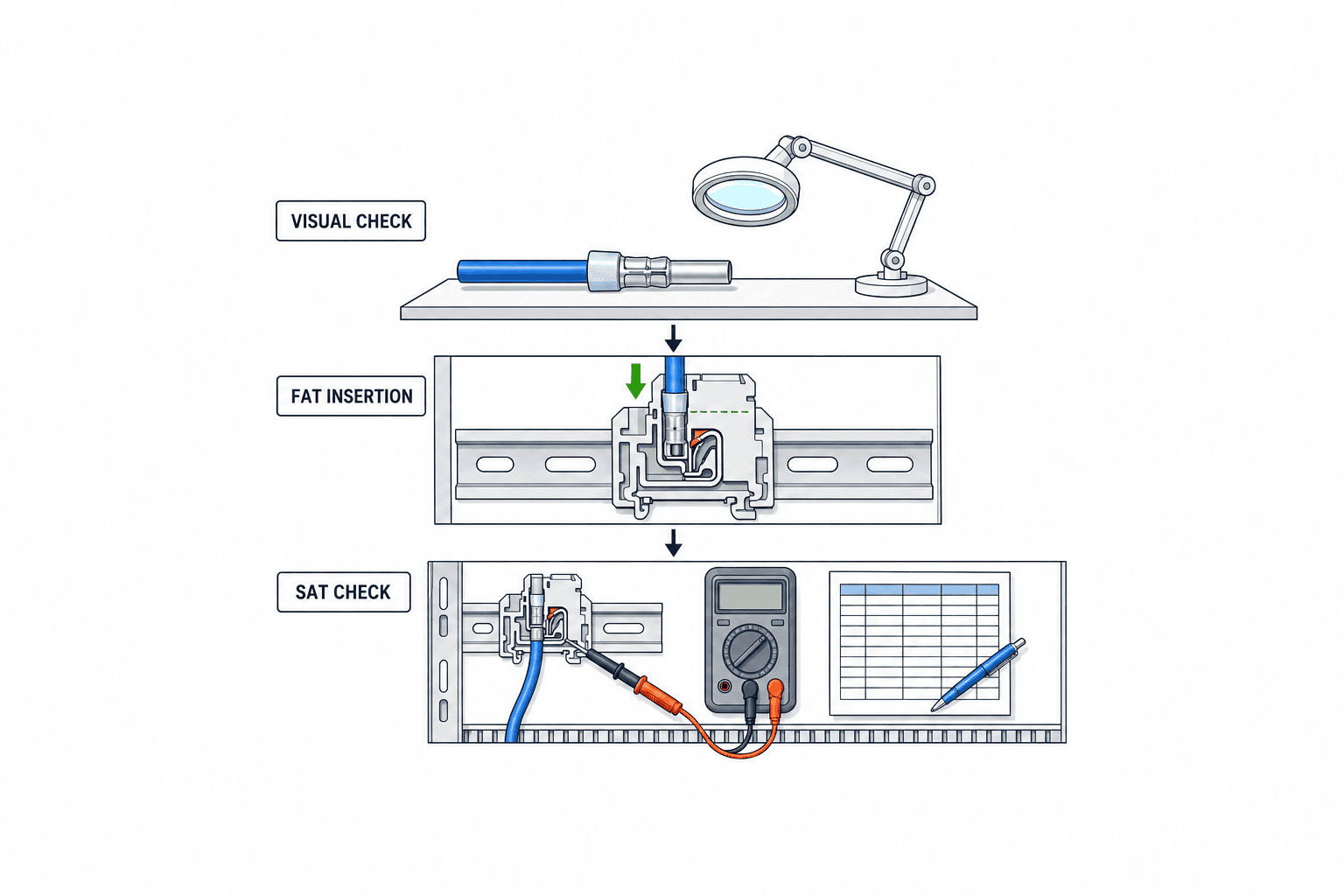
Inspect the result for a cracked barrel, excessive burrs, crushed collar, escaped strands, insulation caught in the crimp and wrong crimp position. Trial-insert it into the exact receiving terminal. Confirm full insertion, the specified screw or spring operation, insulation placement and a reasonable wire bend. A gentle manual tug after assembly can reveal a missed connection, but is not a quantitative pull-out test of the crimp. A destructive pull test belongs on samples; its method and pass criteria must come from the adopted manufacturer information, applicable standard and project specification. Do not copy a universal force value from another wire size or device.
Crimp retention, clamp retention and electrical performance are distinct questions. Weidmüller’s technical brochure explains that a ferrule also deforms in its clamping system and evaluates behaviour in different connection systems; a microsection or crimp density alone does not settle the whole connection. A continuity meter at one instant is likewise not proof of proper conductor preparation or full insertion. Define visual checks, sample tests, terminal checks, continuity and functional tests as separate records.
When commissioning a pull-test plan, define wire type and size, ferrule and tool part numbers, lot, sampling point, pull direction, calibrated equipment, criterion source and containment if a sample fails. Choose inspection frequency to match the project risk and contract: all-piece visual inspection, first-piece and changeover samples, and lot sampling are different controls. Retain failed samples and photos. If failures repeat, investigate tool wear, wrong sleeve size, stripping damage and geometry before changing tool settings by guesswork.
Put the combination and evidence in the RFP
A useful request for quotation attaches the wire and terminal schedules and specifies: connection identifier; approved wire and ferrule; tool and die; stripping and crimping method; inspection; record format; site-work boundary; and substitute approval owner. Ask the bidder to price material, processing, inspection, FAT support, field termination and spares separately. A cheaper ferrule price does not indicate a cheaper accepted panel when sample testing and rework have been omitted.
Request the data sheet for the actual terminal and ferrule, tool evidence, an example first-piece record and the proposed nonconformity process. Find out whether a certificate covers a ferrule alone, ferrule plus tool, or the full terminal connection; do not infer whole-panel approval from a component marking. Where the Japanese owner, Thai fabricator and machine OEM share responsibility, use part numbers as identifiers and provide a bilingual work instruction. A change must update the BOM, terminal schedule, drawings, instructions and inspection records together.
For a PLC I/O expansion, map the PLC plug, intermediate terminal and field sensor connector as three different connection points. The same wire may need different termination at each end. The shop demonstrates first pieces for the PLC and rail terminal at FAT; the field cable end is finished and inspected at SAT. If the cable, ferrule lot or tool changes, use the agreed changeover check before production continues. A first piece once accepted does not certify every later setup.
FAT: inspect first pieces, representative samples and the built cabinet
Before FAT, collect the approved compatibility table, tool inspection record, first-piece photos, defect examples and sample-test results. During witness testing, follow one connection continuously from package and wire marking through the actual crimp tool, crimped sample and terminal insertion. Select representative points across the smallest and largest wire sizes, tight entrances, twin ferrules if allowed, frequently serviced terminals and field-wiring boundaries.
Inspect the finished cabinet for wire and terminal identifiers, exposed metal, insulation position, bend allowance and clamping. Follow the device maker’s torque instruction for screw terminals and insertion/removal instruction for spring terminals. If the contract calls for removing and reinserting samples, specify who restores and retests them. Randomly disturbing every connection can alter the completed installation. Tie FAT acceptance to the approved table and recorded tests, with open deviations and corrective action listed explicitly. Leave field-only work as named SAT items.
SAT: verify field cables and maintainability
At the installed machine, confirm the actual field cable, tool, die and replacement ferrule still match the approved combination. Cable substitutions, changed wire size, spare-wire use and restricted access are common sources of variation. If a different tool must be used on site, approve a new first piece and check insertion before repetitive work. Confirm both wire-end labels and I/O response against the as-built schedule.
The real cabinet access angle may differ from the FAT bench. Check door clearance, lighting, tool access, adjacent wires and bend room. A wire that needs severe force or bending to enter a terminal indicates an installation problem; record and correct the layout or routing. For maintenance handover, deliver the approved ferrule and tool part numbers, stripping instruction, first-piece photos, inspection method, accepted substitutes, spare stock and rework allowance. A visibly deformed sleeve or loose conductor should be remade before reconnection. Avoid aggressive routine tugging that can damage good wiring.
Troubleshooting by failure mode
The crimped end does not enter: confirm part numbers, measured profile, collar clearance, strip length and terminal condition. Do not force it in or machine the terminal entrance. Evaluate an alternative crimp or uninsulated sleeve only with the terminal maker’s approval and a new insulation check.
Continuity passes but the wire moves: separate wire-to-ferrule retention from ferrule-to-terminal retention. Investigate strand damage, sleeve size, tool setting, complete insertion and clamp operation. Replace the suspect connection and define the other products made with the same tool or lot.
A collar is crushed: check crimp position, die contact, wire insulation and collar size. Do not accept solely on appearance; verify exposed metal and terminal clearance.
Two wires are squeezed into a single-wire sleeve: stop and verify whether the circuit and terminal permit two conductors. If so, select an approved twin ferrule and tool. Otherwise revise the terminal or bridging design and drawings.
The field cable has changed: compare conductor construction and insulation diameter as well as cross-section. Re-approve a first piece and update parts and records before mixing it with approved stock.
RFP, FAT and SAT checklist
| Stage | Evidence | Decision |
|---|---|---|
| RFP | Wire, terminal, ferrule and tool schedules | Each connection has an owner and approved combination |
| Design approval | Device instructions, strip length and first fit | Actual terminal accepts the profile |
| Production start | First pieces, tool check, visual examples | Each representative combination is traceable |
| FAT | Sample tests, insertion checks, cabinet tests | Deviations and affected scope are closed |
| SAT | Field-cable first pieces, tool and I/O checks | Site changes return to the approval table |
| Handover | As-built, spare parts and rework instruction | Maintenance can reproduce the connection |
Frequently asked questions
Are ferrules mandatory on all fine-stranded panel wires?
There is no blanket answer. Check the receiving device, conductor type and project requirements. Even where a terminal accepts a ferrule, it may restrict sleeve length, collar, size or crimp profile.
Which is better, square or hex crimping?
Choose to suit the actual clamping space and manufacturer instructions. Test the crimped sample for fit, insertion direction and secure clamping. Neither profile is universally best.
Can we substitute ferrules of the same colour?
Colour does not prove dimensions, standards scope or tool compatibility. Compare part numbers and data sheets and trial-fit in the receiving terminal.
Does a FAT continuity check replace crimp inspection?
No. Verify the approved component combination, first piece, visual quality, insertion and appropriate sample testing separately. Assign the field-terminated part of the connection to SAT.
Should every production connection undergo a pull-out test?
A destructive pull-out test consumes the sample. Set an inspection and sampling plan based on the manufacturer’s instructions, applicable standards, customer requirements and project risk. Do not impose an unverified universal force threshold.
What if a locally sourced substitute is needed in Thailand?
Submit the replacement wire, ferrule, tool and terminal as one combination. Compare dimensions, applicable instructions, a first-piece fit and inspection evidence. After approval, update the BOM, terminal schedule, work instruction and spare-parts list under the same revision; a similar certification name alone does not establish compatibility.
Put the connection-level approval table at the centre of acceptance
Ferrule quality is the result of a matched wire, ferrule, tool and terminal. Approve the sizes and geometry, confirm them on a first piece, inspect production and record the factory and site boundaries. The same table can then support fair supplier comparison, FAT and SAT decisions and future maintenance. TOMAS TECH helps manufacturers in Thailand structure control-panel RFPs, terminal schedules and practical acceptance plans. Contact our team with the drawing scope and site conditions when a connection-level decision is holding up a project.
Primary references
- WAGO: Using Ferrules — connector-specific limitations, strip length and orientation.
- Phoenix Contact: What you should know about ferrules — square crimp and round compartment warning.
- Weidmüller: Wire end ferrules — crimp profile applications.
- Weidmüller: Technical information — preparation and tool selection.
- Weidmüller: Wire-end ferrules technical brochure — insertion and clamping-system evaluation.
- Phoenix Contact: Ferrules — product categories.
- IEC: IEC 60204-1:2016 + AMD1:2021 — scope of machinery electrical-equipment standard. Confirm product-specific criteria separately.
This guide reflects publicly available manufacturer and standards-publisher information checked on 9 November 2026. Verify the current installation instructions, applicable standard edition and project acceptance criteria for the selected products.


