


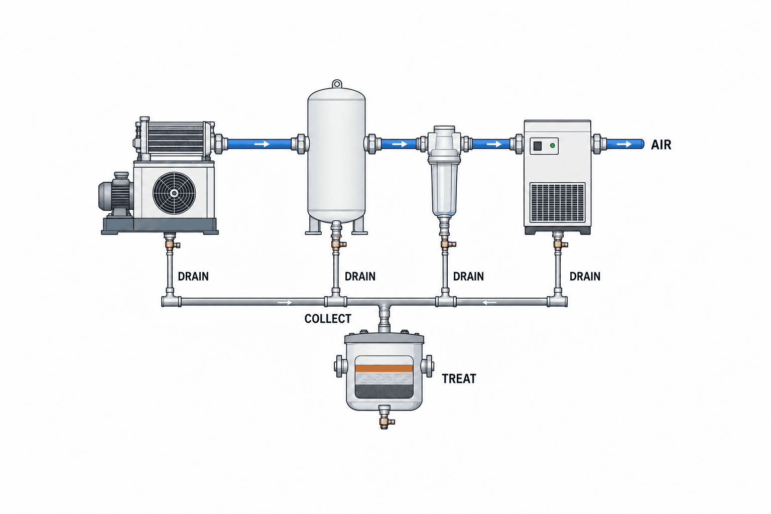
When planning a compressed-air condensate drain monitoring system, start with the drain points, not a shopping list of valves. Condensate can collect at the aftercooler separator, receiver, filters and refrigerated dryer. The factory must know where it is removed, what happens if removal fails, who receives a fault, and where the liquid goes. An alarm contact can reveal some failures, while an obstructed discharge line or an undersized downstream separator may need a separate check. This guide takes a Thai factory from site survey and quotation through commissioning and routine maintenance.
Separate condensate removal from monitoring
Condensate forms as moisture in intake air is compressed and then cooled. The drain removes collected liquid from a defined point; the monitoring system records equipment state, reports a problem and routes the response. Those are related but different functions. A green icon on a screen is not proof that liquid has physically reached its intended destination.
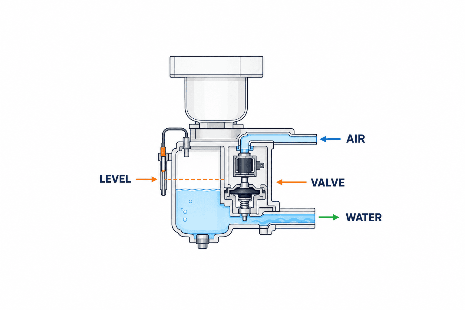
An electronic level-controlled drain senses liquid in a collection chamber and opens a valve when the set level is reached. BEKO describes a capacitive sensor and pilot-operated solenoid valve for BEKOMAT. Kaeser’s ECO-DRAIN also operates according to liquid level, with an external alarm contact available on specified models. A timer drain opens at preset intervals. The US Department of Energy notes two possible problems with a timer: opening when little liquid is present can waste compressed air, while a short opening can leave condensate behind. That does not make every timer drain unsuitable. The right choice depends on actual loading, supervision and what happens when power fails.
Treat “zero loss” as a manufacturer’s description of normal drain operation under specified conditions. It is not a promise that every pipe fitting, manual override and failed valve in the factory is leak-free. Likewise, an alarm contact reports the conditions defined in its model’s manual. A normal contact cannot certify discharge volume, oil-water separation or permission to release treated water.
How this differs from dew point, flow and leak monitoring
Compressed-air dew point monitoring evaluates the water vapour remaining in the air and dryer performance. Drain monitoring checks whether liquid already separated from the air leaves each collection point. A local drain line can block while a dew point instrument still shows an acceptable value. Conversely, a drain may work while the dryer fails to achieve the required air quality. Aligning both signals on one timeline helps diagnosis; one does not replace the other.
Compressed-air leak detection looks for unintended air consumption or escape. A manual drain left cracked open or a timer valve that fails to close can become a leak. A drain stuck closed may not increase air use at all, but instead leave water in the system. Flow and power trends can confirm system-level changes; point-specific drain faults still require relevant drain signals and inspection.
Build a register of every drain point before procurement
Walk the compressed-air train against the as-built drawing: compressor package drains, aftercoolers, moisture separators, receivers, prefilters, refrigerated dryers, final filters and low drop legs. Include equipment backsides and pipework left behind after expansions. For each physical point, record a unique ID, equipment and location, operating pressure, load, condensate source, existing drain model, power supply, alarm interface, discharge destination, access for service and department owner. A list containing only equipment names cannot support design or later fault response.
Hot or humid intake conditions may change condensate production, but do not insert a fixed “Thai rainy season litres per hour” figure into an RFP. Compressor run hours, inlet conditions, flow, aftercooler performance and dryer configuration all matter. Give the OEM the conditions required for sizing. Where possible, observe both a higher-load and lower-load period. Mark unknown inputs as estimates, document the assumption and agree to revisit it after initial operation.
Rank points by consequence: potential product contact, paint or instrument-air sensitivity, unattended hours, discharge onto the floor and the number of downstream users affected. A simple supervised low-risk point may not need a networked drain. Decide monitoring depth by the impact of failure and how long a failure could remain unnoticed.
Draw the inlet and outlet as separate paths
The drawing should show isolation and maintenance space on the compressed-air side, then trace the liquid outlet through its hose or pipe, collection header and oil-water separator. Check the receiving line for backpressure, blockage and service access. A transparent hose can help inspection but is not continuous proof of flow. “To drain” is too vague as an outlet description: identify a floor, vessel, header or separator, with drawing and photograph references.
Adding electronic drains everywhere can simply move the bottleneck downstream if the collection line or oil-water separator is undersized. Recheck the separator against every connected point, including later equipment additions. Oil and contaminants may enter condensate; the factory must confirm the local conditions applying to its actual discharge route. A threshold quoted from another country should not be treated as a Thai requirement.
Compare drain types on more than purchase price
Manual valves are simple where periodic checks are dependable, but opening and closing depend on people. A float trap responds to liquid level and can avoid air loss when working properly, but sediment and moving parts need attention. Timer drains need settings that reflect changing liquid loads. Electronic level drains can offer diagnostics and remote alarm signals; they also need power, compatible electronics and obtainable service parts.
| Type | What initiates discharge | Monitoring question | Typical blind spot |
|---|---|---|---|
| Manual valve | Operator action | Who checked and when? | Forgotten opening or closure |
| Timer drain | Clock setting | Is timing suitable for current load? | Air venting or insufficient opening |
| Float trap | Mechanical liquid level | Is the float or outlet blocked? | No external fault signal |
| Electronic level drain | Sensor-detected level | What does the fault contact actually mean? | Normal contact mistaken for proven flow |
Check each model’s permitted pressure, supply voltage, connection thread, condensate type, environment and low-pressure behaviour against the actual site. Published capacity has sizing assumptions. Request the manufacturer’s selection basis for the specific point instead of copying one model across all locations. Condensate from oil-injected and oil-free systems may require different material or treatment choices.
Do not collapse blockage, power loss and lost communications into one signal
Read the proposed model’s manual for detected faults, detection delay, reset rules, test function and contact state during a supply failure. BEKO describes a self-clearing attempt followed by an alarm for some fault conditions; it would be wrong to assume every model follows the same algorithm. Ask the vendor to attach model and manual references to the quotation and specify the normal, fault, wire-break and power-off states.
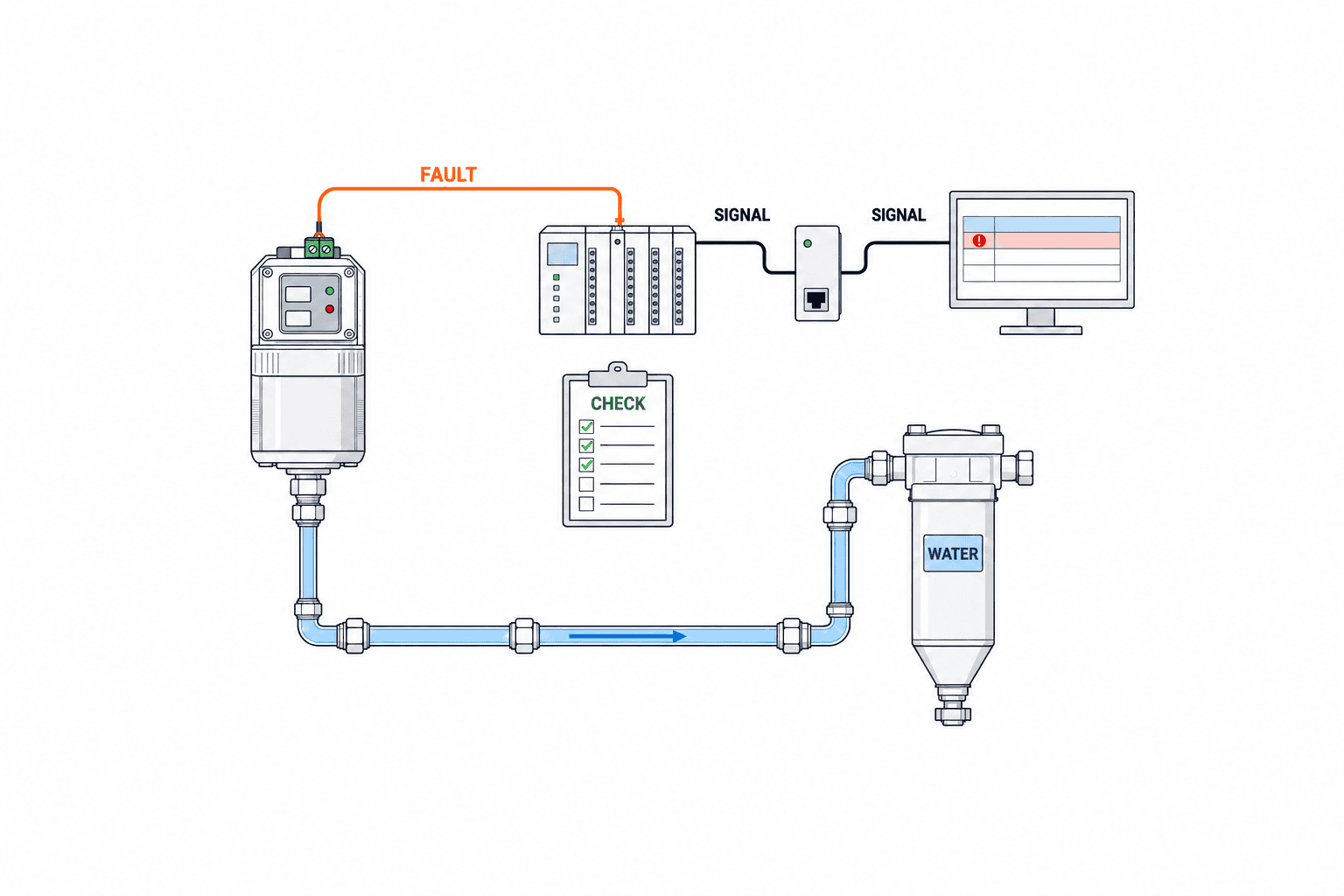
At the monitoring end, distinguish a drain fault from stale data, broken wiring and gateway power loss. Display the last valid time and data quality; do not retain the last green value indefinitely after the source disappears. If an alarm is suppressed for maintenance, save the reason, user and expiration. This prevents a software acknowledgement from being mistaken for a repaired physical drain.
Valve-open commands and discharge counts can reveal trends, but they are not a measurement of discharged liquid. An inlet plug, outlet obstruction, excessive downstream backpressure or mechanical valve failure can prevent flow after an open command. Decide whether a high-risk point needs another observation method or an inspection port. Fitting a liquid flowmeter at every point is unnecessary; naming the observation gap is essential.
Design the OT data around physical drain points
For each tag define point ID, signal name, normal value, fault value, power-off value, I/O channel, transport, timestamp, alarm owner and maintenance owner. Keep the physical point ID stable even when a drain model is replaced. If a model exposes level, cycle counts or diagnostic codes, attach its interface specification and define units, update intervals and invalid values. Do not label a single dry contact as “discharge volume” in the dashboard.
The first screen should help maintenance personnel find the device. Place point IDs on a simple compressor-room schematic, with start time, duration, acknowledgement, site finding and recovery time. Then define recipients and escalation by shift. A red light on a central screen does little for an unattended night shift. Event recording may be enough for contact inputs; saving the same normal value every second is not inherently more useful. Where brief faults matter, test event retention, polling and latching.
If wireless is proposed, test metal-room coverage, battery replacement and reconnection after power loss at the site. If connecting to a production PLC, specify the approved I/O boundary and avoid unreviewed control changes. Keep the as-built network route and ownership of future edits in the handover pack.
Complete the workflow after the alarm
The response card for each point should direct the recipient to verify timestamp and location, then safely check pooling, discharge piping, indicators and power. Qualified maintenance staff can examine diagnostics, valve function and the downstream separator. Opening a pressurised pipe or electrical compartment requires the factory’s isolation, authorisation and residual-pressure procedure. Monitoring software does not make the physical task safe by itself.
Set priority by consequence. A point where water could affect a product may demand prompt inspection; a redundant separator point may be handled in an approved inspection window. Test delays, repeat alerts, shift handover and recovery confirmation during the pilot. Do not simply lengthen a threshold to silence a noisy alarm without finding its cause.
Write an RFP that makes bids comparable
Attach the drain-point register and piping drawing. For each point state operating pressure, airflow or compressor data, hours, environment, condensate characteristics, existing equipment, available power and I/O, and existing collection and treatment equipment. Ask each bidder for the model selection basis, excluded conditions and a separately priced scope for mechanical work, wiring, PLC/gateway setup, display, notification, SAT, training, spares and service.
| RFP line | Vendor evidence | Acceptance focus |
|---|---|---|
| Survey | Point register, photos, drawing differences | All points and extra work identified |
| Drain | Model, sizing calculation and limits | Pressure, medium, power and spares |
| Collection | Inlet/outlet drawing and separator check | Blockage, backflow and access |
| Signals | Contact specification and I/O map | Fault, power loss and missing data |
| Screen | Tags, permissions and notification routes | Can the operator act? |
| Handover | FAT/SAT records and training | Failure cases and named owners |
“Zero loss” and “IoT ready” are insufficient comparison columns. One product may only offer a dry contact; another may transmit detailed diagnostics. Choose according to the fault response required, existing OT infrastructure, local service and spares. Distinguish mandatory requirements, desirable functions and site-dependent checks. Include software licences and change authority if an existing PLC or SCADA system will be modified.
Compare lifecycle and downtime costs without inventing a payback
Include equipment, installation, controls, spare modules, maintenance, oil-water separator consumables, training and testing in total ownership cost. A plant-specific business case can use its own failure records, time to detection, restoration time, verified air leaks and quality losses. Avoid claiming that every factory saves a fixed percentage. Preventing water carryover and reducing compressed-air loss are different benefits; measure them separately. For power savings, align kW/kWh, compressor state, pressure and production conditions as discussed in power-meter verification of compressed-air improvements.
A pilot should cover different types of point, such as an aftercooler, receiver, dryer and filter, without requiring a full-site replacement. The test is valuable when staff can reproduce fault detection, notification and recovery. A pilot with no spontaneous faults does not prove failure detection. Simulated electrical inputs can test the alarm route without deliberately introducing water into a critical production line. Record why each candidate model was accepted or rejected, including power, service access, contact logic and availability of local parts.
FAT and SAT must verify both signals and liquid movement
At FAT, check tag-to-I/O mapping, normal/fault/broken-wire/power-off states, delays, reset, recipients, time stamps, event history and permissions. Check the manual before using a TEST button: it may exercise a valve or contact but need not prove real condensate flow. Simulate failure safely and set boundaries so testing does not affect production control.
At SAT, verify nameplates, pipe direction, leaks, supply, signal wiring, valve action, actual discharge, the collection path to treatment and matching point IDs on site and screen. If little condensate is present, use an OEM-approved test method under safe isolation and record “liquid flow not yet observed” with a date for recheck. An empty valve opening is not proof of discharge capacity. Record point ID, time, pressure, compressor state, action, expected result, field result, screen result, evidence, witness and open issue for every case.
Power-off and network-loss tests require approved boundaries. Where every point cannot physically discharge on the handover day, leave those points as conditional checks instead of marking them passed. The useful handover is a repeatable procedure and an owner, not only a dashboard screenshot.
Maintain and update the installation
Routine checks should cover indicators, alarm history, blocked lines, leaks, manual-valve positions, the collection header and separator service. Follow the adopted model’s maintenance instructions for seals, valves, modules and media, then adapt inspection frequency when operating conditions change. No alarms is not proof of health; periodically test the notification path and review stale or disabled tags.
Compressor additions, dryer changes, higher production, pipe extensions and separator replacement can alter drain capacity and the meaning of its signal. Tie the point register to management of change. After a replacement, confirm leaks and discharge operation, then retest the tag and alarm. Review not only fault count but alarm-to-inspection time, repair time, repeated failures and disabled points. A recurring alarm may come from dirt, pipe slope, backpressure or access rather than the drain model alone.
FAQ: compressed-air condensate drain monitoring
Is a fault contact enough to confirm discharge?
It reports the faults defined by that model. It may not detect every blocked outlet or downstream treatment issue. Decide whether high-consequence points need a physical flow check, inspection method or separator alarm. Document contact logic during power failure and wire break.
Should every timer drain be replaced with an electronic level drain?
No blanket answer is justified. Survey load variation, air venting, consequences of retained water and available maintenance. Compare suitable models, spares and support at each point.
Does a dew point sensor remove the need for drain monitoring?
No. Dew point describes water vapour and dryness at its measurement point; the drain handles separated liquid elsewhere. Decide on both from process-quality needs and the failure consequences at each collection point.
May the discharged condensate go straight to a floor drain?
Oil-injected compressors may put lubricant and dirt into condensate. Confirm collection, treatment and site-specific discharge conditions before release. Even an oil-free compressor does not remove the need to inspect the entire collection route. Do not import a foreign discharge limit as a local rule.
What is the most important acceptance evidence?
Keep separate records that a fault at the correct physical point reached the right person, and that liquid travelled through the intended discharge route. A green status icon proves neither on its own.
A practical implementation sequence
In the first site walk, maintenance and facilities staff identify every physical drain point together and correct outdated drawings. Rank each point by the consequence of failure and the time the current inspection method would take to discover it. “Unattended overnight and water may accumulate until morning” is a better alarm-design requirement than “critical, therefore IoT.” List points that will not be replaced, too: sometimes the existing device is sound but the collection route needs work, or a new device can use existing monitoring infrastructure.
Before ordering, assign ownership along the full path from drain contact terminal through wiring and PLC to notification screen. Otherwise commissioning may reveal an expensive gap: a supplier supplied a contact but no contractor connected it to the operator. Plan test windows around approved shutdowns and operating states likely to produce condensate. It may be reasonable to verify tags and wiring on one day and actual liquid movement on another. Record any condition not yet tested and the operating state and date for recheck. Never introduce water into a quality-critical line merely to make an acceptance photo.
After handover, check whether the shift recipient could find the right point, log the field finding and close the repair, not only whether the alarm sounded. Confirm spare-parts location and ordering route. Keep the current point register, response card and manual revision together so the process survives a change of maintenance personnel.
Conclusion
A useful system starts with a point register and ends with a verified response. Specify drain sizing and signal meaning, collection and oil-water treatment, alarm ownership and separate FAT/SAT evidence for electronics and liquid flow. Level-controlled electronic drains can reduce unnecessary air release and provide useful fault outputs, but a normal output alone cannot certify successful discharge. Pilot the critical points under the factory’s operating conditions before scaling up.
TOMAS TECH can help map drain points, connect approved signals to existing PLC and monitoring systems, and prepare an RFP and acceptance plan. You can contact us even while the equipment models are still under consideration.
References
- US Department of Energy, Improving Compressed Air System Performance.
- BEKO TECHNOLOGIES, BEKOMAT product overview.
- BEKO TECHNOLOGIES, BEKOMAT 16 CO manual.
- BEKO TECHNOLOGIES, Networked compressed air treatment.
- Kaeser, ECO-DRAIN.
- Atlas Copco, Condensate removal 101.
- ISO, ISO 8573-1:2010 concerns compressed-air cleanliness classes, not drain performance.


