


The stopping accuracy printed in an AGV catalogue does not tell a Thai factory whether a box can transfer to a conveyor or whether a robot can pick a part from the vehicle. Stopping position, heading, deck height, station guides and a signal that actually verifies position must all fit the receiving process’s tolerance. This guide connects docking requirements, positioning methods, position verification, conveyor and robot-cell interfaces, RFP, FAT and SAT into one procurement decision. It applies to AGVs and AMRs at fixed transfer points.
Procure a safe handover, not simply an arrival
A vehicle reaching its mapped goal is different from a load crossing the interface to fixed equipment. Lateral offset, entry angle, floor slope, tire condition and load deflection can all shift the contact point even when the route is completed. If a robot picks from a tray on the vehicle, the part can move within the tray as well. An acceptance rule that checks only a navigation-complete bit leaves the last approach and handover undesigned.
Write an event contract first: which load, at which station, with which evidence, can be transferred to which machine? One example is: “The AGV carrying the assigned returnable tote enters station A; only after vehicle pose, deck height, receiver availability and stopper state are verified may the conveyors run.” Completion should mean that the receiving sensor has detected the tote, the vehicle-side sensor confirms it has left, and the transport ID has changed once. Then competing systems can be evaluated on the same outcome.
For route and fleet planning, see our AGV layout design guide. The wider conveyor handshake is in our conveyor-top AMR integration guide. Here the focus is the last approach, stopping, independent verification and permission for connected equipment to act.
Derive docking tolerance from the receiving equipment
Do not put a generic “stop within X millimetres” in an RFP before measuring the handover. At a conveyor, examine roller height difference, lateral overlap, the fore-aft gap, tote underside, guide width and stopper position. A wide guided opening accepting a slightly skewed box needs different positioning from a rigid fixture entering a narrow slot. At a robot cell, the limits are the gripper’s capture envelope, part variation, tray position and any vision correction.
Tolerance has more dimensions than X and Y on a map. Heading, deck height, pitch and roll, load mass and centre of gravity, and cargo overhang can all matter. CAD on a level floor hides height changes produced by joints, slopes and vehicle tilt. SICK’s NAV350 instructions note that recommended reflector mounting heights do not account for uneven floors or AGV tilt under load. Verify installation height and end-to-end handover tolerance on site. Do not treat a maker’s sensor figure as the complete floor-and-load handover tolerance.
Create a tolerance sheet for each load and station. Include fore-aft and lateral displacement, yaw, height gap, load tilt, movement while stopped, measurement uncertainty and action when out of tolerance. Name the datum surfaces and units. “Measured from vehicle centre” is not interchangeable with “measured from the box’s front edge.” Values are contractual limits derived from the actual process and risk, never invented industry-wide guarantees.
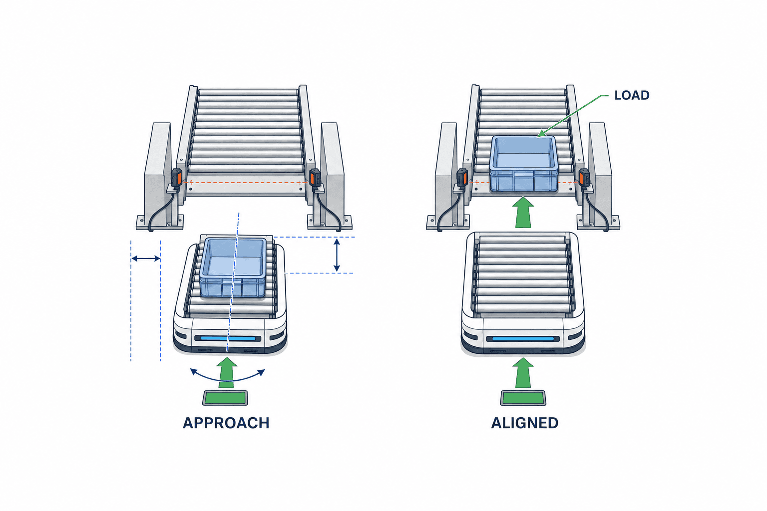
Separate coarse navigation, final positioning and contact confirmation
A single sensor need not carry the entire job. First, the factory navigation system brings the vehicle to a staging point. Second, a station-specific marker, reflector, camera, LiDAR contour, magnetic tape or other method refines relative pose. Third, a separate signal verifies seating, contact, deck height and stopper state as needed. The important comparison is which error each stage removes and what evidence proves completion.
Nav2’s Docking Server describes navigation to a staging pose, dock detection, refinement during approach and a separate contact or charging check. It also supports non-charging docks, including static infrastructure such as conveyor ends and dynamic locations such as pallets. This architecture does not guarantee that a particular commercial AGV implements the same sequence; it illustrates why “arrived” and “docked” should be separate states.
OMRON’s product data lists magnetic-floor-tape positioning as an option and a charging docking target as a distinct component. SICK describes vehicle localization based on 2D LiDAR scans of surrounding contours. These official sources establish the available approaches; they do not certify a specific result on your floor with your load. Require a site trial. Ask how a vehicle enters: forward, reverse or after turning in a tight aisle. Check whether a marker can be hidden by cargo or workers and how it will be remapped after cleaning or floor work.
Verify position with evidence beyond the arrival bit
The pose stored in the vehicle map does not directly prove alignment to a fixed machine. Record relative pose after arrival, mechanical seating, load and receiver sensors, and the interlock granting transfer separately. The right evidence depends on the task. Roller transfer needs alignment of the box entry and conveyor surfaces. Robotic picking needs the part inside the gripper’s reachable and taught envelope.
A contact switch proves contact, not the correct load height. Charging current proves charging, not a conveyor handover. A vision marker can estimate relative pose but may be occluded or have delayed data; decide whether to recheck after final stop. Nav2 also separates dock detection, docked state and charging state. In the specification, write one line for what each signal proves and one for what it does not prove.
On failure, do not let the vehicle repeatedly push into the station without a defined rule. Specify when it may back away and retry, when it must stop, when the receiver must hold and who may clear the fault. Record docking ID, vehicle, station, load, target, measured result, attempt count, reason code, timestamp and configuration version. A failed transfer should not leave only an “arrived” status in the upper system.
Conveyor transfer joins geometry and handshake
Vehicle arrival alone cannot start rollers. The load must fit both surfaces; the receiving lane must be empty; its stopper must be ready; and any guarded access must be in the required state. If the vehicle and stationary conveyors both drive, test what happens when only one moves. Keep “position verified” from the AGV, “ready to receive” from the station and “permission to transfer” from the coordinating control as distinct signals.
Confirm completion from both sides: the vehicle load sensor becomes clear and the receiver sensor detects the tote, then the transport and load IDs are advanced once. If only one side changes, the box may be stranded across the gap. Blindly replaying the command can push it further or record a duplicate. The exception workflow should establish where the load physically sits and which signal failed. A reverse transfer uses the same principle with source and receiver roles exchanged.
OMRON’s transport application page illustrates AMR handovers to lines through roller or belt tops and automated docking stations. It describes an application, not a guaranteed tolerance for your plant. The conveyor-top AMR integration guide covers the whole state handshake. The position-specific requirement here is simple: no transfer permission without verified docking.
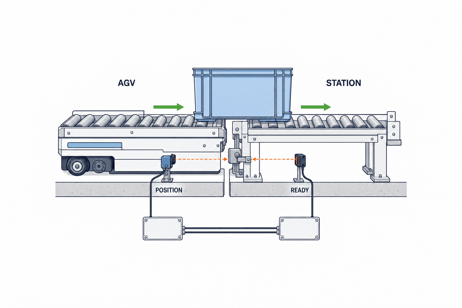
A robot cell needs a workpiece datum, not only a vehicle datum
If a robot arm picks from a vehicle, the parked vehicle may be in tolerance while the part is not. Tray play, pallet placement, rack deflection and shifting during travel remain. Treat the effective error as a chain from vehicle stop through deck and tray to the workpiece and measurement system. Share the realistic worst combinations with process engineering rather than assuming that one vehicle accuracy figure covers every link.
One design mechanically locates the AGV, then uses a cell camera or sensor to remeasure the part datum and correct the pick. Another transfers the pallet into a fixed cell fixture before picking. Compare cycle time, part rigidity, changeover, cleaning and maintenance as well as position performance. A better vehicle stop may cost more than a simple station guide; a camera may reduce mechanical fixtures but introduce lighting and calibration work.
Permission to enter or operate a robot cell depends on both safe state and process readiness. A person inside, a robot not at its safe waiting pose, a gripper still holding a part or an unexpected vehicle should block production start even if docking completed. Safety functions require design and validation by qualified equipment makers and integrators under the applicable current requirements. Positioning logic described here is not a substitute for safety validation.
Survey floor, load and changing surroundings
At each Thai factory station, measure floor flatness, joints, drainage slope, steps, wet or oily patches, temporary storage and forklift crossings. Check the view from the beginning of the final approach, not only at the stopping point. For reflectors, floor markers, image markers or contour localization, test effects from moving racks, people, stacked products, lighting and cleaning. SICK’s NAV-LOC instructions describe an onboard 2D LiDAR comparing current contours with a stored map; changes to those contours belong in site tests.
Test empty and loaded vehicles, light and heavy or offset loads, different pallet heights and tire condition near the maintenance limit. Load-induced tilt can change conveyor height at the same planar position. If a guide or dock is floor-anchored, include anchoring, floor works and safe maintenance access. Available network and power do not automatically make a transfer gap safely accessible.
Record measured conditions in drawings and photographs; label unmeasured items “unverified.” Bids built on different site assumptions cannot be compared. If a line or rack is scheduled to move, evaluate initial and future docking arrangements. Specify remapping and SAT retests after relocation in the contract.
Compare method combinations, including independent verification
Magnetic tape, reflectors, LiDAR contours, visual markers and mechanical guides solve different constraints. Magnetic tape creates a local reference but needs floor installation and upkeep. Markers and reflectors need a maintained line of sight. Contour methods depend on sufficiently stable surroundings. Mechanical guides can constrain the final load position but need wear, impact and adjustment management.
Compare initial work, adding stations, layout changes, reteaching after maintenance, dust/oil/lighting sensitivity, approach direction, verification independence and escape on failure. Catalogue accuracy figures come from different loads, floors and measurement points. Use one real station and the same load and approach patterns to compare candidates.
If the same signal declares both “arrived” and “safe to transfer,” a common error can escape detection. Combine an independent position sensor, seated switch or load sensor as the process risk requires, and prove that the connected equipment stays still when a vehicle is incorrectly placed. Adding sensors alone does not automatically make a system safe or reliable; validate their failure behavior.
Put data and ownership into the RFP
List stations and loads, approach direction, transfer method, minimum/maximum dimensions, cycle requirement and peak simultaneous activity. Then give datum and tolerance sheets, measurement methods, post-stop validation, retry and manual intervention. Demand proof with actual loads and floors, not only catalogue numbers. The pass/fail limit must come from the process.
The signal table should distinguish vehicle arrival, position verified, station ready, transfer permit, transfer start, load passage, completion, fault and reset. Define sender, receiver, retained state and recovery after a network gap for each. Decide who reconciles a mismatch between transport ID in WMS/MES and machine state in the PLC. MassRobotics’ interoperability material concerns sharing basic AMR status across makers; it does not set the mechanical tolerance or cell safety for this dock. Upper-layer protocol compatibility cannot replace an interface test.
Deliverables should include station layout, floor and anchor plan, marker/reflector positions, vehicle-to-machine interface drawings, sensors, signal and state diagrams, FAT/SAT sheets, logs and reteaching procedure after replacement. When AGV, conveyor, robot-cell and IT vendors divide the work, appoint one owner for the complete handover result. Name a first fault-triage contact for every abnormal state so “the other vendor’s equipment” does not become a gap.
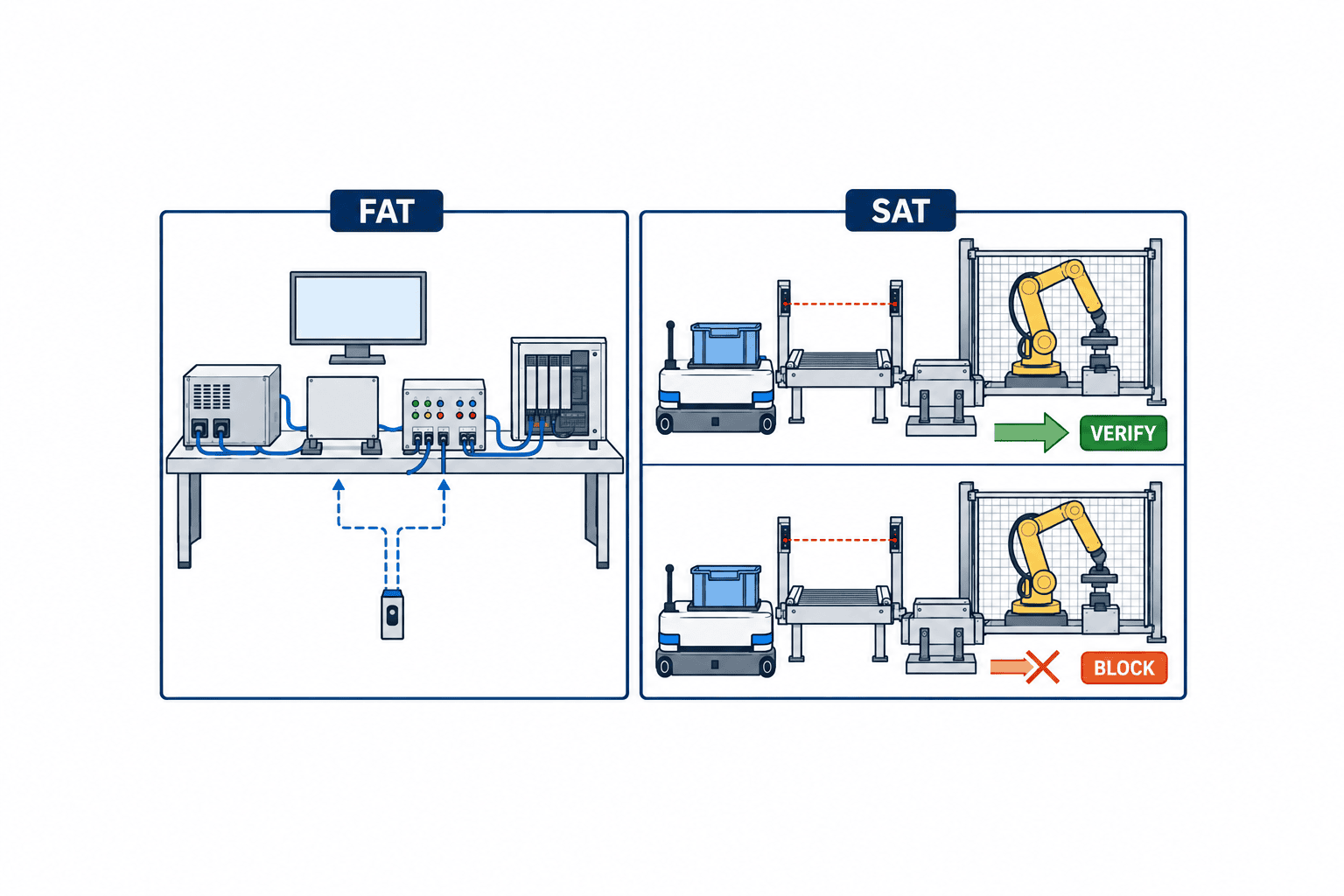
Separate FAT and SAT
FAT checks state transitions before shipment using the real or equivalent control stack. Inject normal approach, missing dock, pose out of tolerance, failed seating, full receiver, timeout, network loss/recovery and conflicting load sensors. Verify that no machine moves without permission. Check event IDs, inputs, decisions, outputs, timestamps, configuration versions, retry and manual reset rights. FAT cannot reproduce the plant’s floor and load variations, so it cannot be the sole proof of positional performance.
SAT measures position, heading, height and actual transfer on the installed floor with production loads, workers and neighboring vehicles. Include approach to retreat, light and heavy loads, different pallets, transfer directions and peak traffic. Test marker occlusion, normal and just-cleaned floor, and temporary communication loss. A required negative case is that a vehicle outside tolerance does not start the conveyor or robot cell.
Use measurements relative to the station datum, not only the vehicle’s self-reported pose. Record instrument, method, repetition count, load and floor state. A successful video hides variation and failure response. Keep all attempts and denominator by condition. After correction, link the changed setting to a retest and test nearby conditions that could have worsened.
Attach photographs of the measurement datum and the placement of each gauge to the test sheet. Measuring the vehicle centre and measuring where the tote meets the receiving roller are different tests, even if both are labelled “pass”. Record the floor reference line, instrument calibration state and the waiting time after the vehicle stops so another tester can repeat the result. Note left-to-right deck differences when loads are uneven. Count docking not found, retries, manual interventions and aborted transfers as separate outcomes; do not exclude them from the total number of attempts. A simple success count out of a hundred attempts can hide repeated failures with one load or during one shift. Link event IDs in the log to physical measurements to find conditions that pass only after a retry. If settings or the floor change after acceptance, repeat the affected conditions with the same test sheet and record the difference and the time needed to restore service.
Example: one AGV, one conveyor station and one robot cell
At station A a returnable tote crosses to a fixed conveyor; at station B a robot picks from a tray on the same AGV. A depends on roller height, lateral offset, tote base and stopper. At B an acceptable vehicle position may still leave a part outside the gripper’s capture range. Do not assign the two stations one generic “stopping accuracy”; derive their tolerances and verification from each process.
At A verify vehicle seating, both conveyor surfaces, receiver availability and tote ID before permission. At B constrain the vehicle, then measure the tray or part datum and confirm that the robot can pick. Different station sensors are consistent with using the same vehicle. They separate reusable vehicle capability from station-specific controls.
A PoC need not finish both stations at once. Start with one station and a load that makes repeatable measurement possible, then carry the same test framework to the second while changing sensor, tolerance and permission rules. Copying the first dock’s settings without testing the second hides equipment and load differences.
Agree on the measurement method before debating pass/fail
Specify the measurement method with the tolerance number. Measuring from a floor stripe to vehicle centre does not directly describe where a tote sits relative to the conveyor roller edge. Use a receiving-machine datum and the load’s transfer contact point. A robot cell may need the tray locator or workpiece gripping surface measured as well. Moving the datum after the test makes results incomparable.
Record instrument resolution and calibration, measurement fixture and operator variation. If uncertainty approaches the tolerance, near-boundary pass/fail decisions will be unstable. Decide which reading controls the contract when vehicle logs, cell sensors and an independent fixture disagree. The self-reported pose is useful for diagnosis but cannot replace the actual relative position. At SAT, compare physical measurements against the operational sensor’s decision so the daily pass/fail signal is validated.
Do not calculate an average from selected successes. Retain every attempt, measurement, retry and distribution by test condition. If several vehicles share a dock, report each separately. Include plausible temperature, wet-floor, battery and tire conditions when they affect approach. Baseline SAT records later help distinguish equipment wear from a changed load.
Close an abnormal transfer as one transport transaction
If a worker guides a failed AGV by hand and pushes the tote onto the conveyor, physical movement and WMS/MES state can diverge. First locate the load and hold the transport ID. After establishing a safe condition, record whether it was redocked, transferred manually or returned. Then complete, cancel or retry the original command exactly once. This prevents a second issue of the same tote.
After communication loss, check which side last received permission. If vehicle and station disagree about completion, do not call the next vehicle until they reconcile. Night-shift instructions should show the concrete cause, load location, contact person and reset authority. Simulate state mismatch at FAT and recover with a real load at SAT. Acceptance includes closing a failed transaction safely and audibly, not only running one normal cycle.
Include local maintainability in method selection
A precise method can still create long downtime if replacement markers are unavailable locally or only an overseas engineer can reteach the system. Quote Thai-language displays and work instructions, locally serviceable parts, remote diagnostic logs and inspection intervals. Decide who reports a marker damaged during floor cleaning or a conveyor leg adjusted by maintenance.
A spare vehicle may have the same dimensions yet differ in sensor calibration, tire wear or deck assembly. Registering it in the fleet is not enough: verify position and load transfer at representative docks. Keep a vehicle–station compatibility table and do not enable automatic transfer for an untested combination.
Monitor and manage changes after go-live
Separate first-attempt success, retry, manual intervention, pose out of tolerance, waiting time and incomplete transfer by station. A high total success rate can hide a station whose retries are climbing because a guide or marker is wearing. Maintenance should inspect looseness, dirt, sensor detection, map/teaching version and tires rather than merely increasing a setting to hide symptoms.
Floor repair, moving conveyor legs, replacing the vehicle top module, replacing markers or reteaching the robot all change docking conditions. Save before/after drawings and settings and rerun relevant SAT cases. Include a negative test that out-of-position equipment stays still. Train operators to stop, report and restart safely, not to push a misaligned vehicle until a green light appears.
Four questions for the final procurement meeting
First, which receiving-machine surface is the position datum? Second, after arrival, who proves alignment to that datum and with which sensor? Third, when pose is out of tolerance, load sensors conflict or communication fails, which actions are prohibited and who authorizes recovery? Fourth, how is completed handover confirmed both by physical load location and by transport ID? If these questions lack answers, comparing vehicle prices does not compare the same docking scope.
Put the answers into drawings, signal tables, state transitions and test sheets, not only sales prose. “Position detected” is ambiguous if it does not say whether the measured object is the vehicle or the tote. “Stop on fault” is incomplete if the tote can be stranded across the gap; the specification must say who supports it and in what order equipment is released. These questions make positioning proposals comparable on the same process boundary.
Frequently asked questions
Is catalogue stopping accuracy enough to approve docking?
No. Its measurement conditions may differ from your floor, load, top module and station datum. Derive tolerance from the receiving process and measure the completed stop against that datum at SAT, including transfer and failure controls.
Are visual markers or LiDAR more accurate?
The method name alone cannot decide. Line of sight, floor and surrounding changes, approach direction, controller, load and measurement point all matter. Compare candidates on the same station and check whether final position is independently verified.
Can a charging dock also serve as a conveyor dock?
It depends on the equipment. Charging current does not prove roller height or tote position. If combined, design charging, position, transfer and departure as separate states and test prohibited simultaneous actions at FAT/SAT.
How many automatic retries should a failed dock allow?
There is no universal number. Separate conditions allowing a safe back-off and retry from those requiring a stop and human review. Recheck pose and obstacles for each attempt, and retain a trace of repeated faults.
Can SAT be skipped when FAT passes?
No. FAT exposes control and signal defects early; SAT proves actual position and handover on the installed floor with real loads, people and adjacent equipment. Specify separate acceptance items in the RFP.
Conclusion: specify the dock as a process boundary
An AGV docking and positioning system is the boundary where a moving vehicle hands a load to fixed equipment. Derive tolerance from the receiver, separate coarse guidance, final correction and position verification, and prevent the conveyor or robot from acting when verification fails. Put signals and ownership in the RFP, state transitions in FAT and real floor-and-load measurements in SAT. This makes competing proposals testable at the factory.
Even if the docking method is still undecided, contact TOMAS TECH. With your load and station drawings, we can help define tolerance sheets, verification and a focused PoC and FAT/SAT plan.


