


When introducing AGVs or AMRs in Thai factories, AGV safety measures cannot be satisfied by vehicle specifications alone. You must verify operations on-site including pedestrian crossings, handover to equipment, floor conditions, and maintenance tasks. This article lays out exactly what to require in procurement specifications, what to check during commissioning, and what to review after start-up.
Three managerial decisions (practical conclusions tied directly to purchase/implementation)
When adopting AGV/AMR, factory executives and site managers must make the following three quick decisions. Use these as items to include in tender specifications and acceptance criteria.
- Document the “minimum safety performance” explicitly: Require vehicle manufacturers to confirm, for the applicable vehicle, the scope of application of ISO 3691-4:2023 and the parts for which the manufacturer declares conformity, and demand verification records for the stop, detection, and alarm functions needed for each hazard. If you set target performance for safety-related control, also request the rationale based on the risk assessment. Clarify that ISO 3691-4 covers driverless trucks and their systems, including preparation of the operating zone in Annex A; site-specific conditions still require a documented risk assessment.
- Include “site risk assessment and phased introduction” in the contract: Create a plan of drawing review → tests on limited routes → phased roll-out, and define stop criteria for each phase (conditions under which deployment is halted if safety parameters are not met). Because safety settings depend on site conditions (floor material, lighting, mixed vehicles, shift structure), follow manufacturer instructions while ensuring the contract guarantees site-side checkpoints.
- Clarify “maintenance / operation responsibilities and training”: Put responsibility divisions (sensor cleaning, software updates, battery maintenance, manual rescue procedures, night/holiday operation rules, etc.) into an operations manual, and require a maintenance contract at procurement that includes initial training and periodic retraining. Training should cover not only vehicle operators but also maintenance staff, forklift drivers, and personnel at load/unload destinations.
These three decisions do more than check for the presence of safety features; by clarifying on-site effectiveness and responsibility, they reduce start-up confusion and rework costs.
Division of responsibilities between the vehicle (manufacturer) and the site (factory): terminology and positioning of standards
To design appropriate AGV/AMR safety measures, do not confuse “vehicle responsibilities” with “site responsibilities.” Below clarifies terms and the role of major standards.
- Terminology: AGV (Automated Guided Vehicle) often refers to vehicles with traditional guidance (magnetic tape, buried guidance) and generally fixed routes; AMR (Autonomous Mobile Robot) refers to vehicles that can select paths dynamically using SLAM or map-based navigation. The industry uses these terms interchangeably, but in specifications state the vehicle’s navigation method, obstacle-avoidance algorithms, safety function composition, and behavior on faults.
- Examples of vehicle (manufacturer) responsibilities: Safety-related controls in vehicle design (sensor selection, emergency stop circuits, software fault detection, physical interlocks), manufacturer user manuals and declarations of conformity, factory acceptance tests, and initial setting instructions for safety functions. These relate to vehicle-side requirements and technical documentation under ISO 3691-4:2023 (see: ISO 3691-4:2023).
- Examples of site (factory) responsibilities: Preparing the installation environment (smoothing floors, managing slope gradients, placing guidance lines and safety partitions), ground signal infrastructure, route design, risk assessments based on site-specific equipment placement, operational rules and procedures, education of area occupants and access control. Use ISO 12100:2010 (general principles for risk assessment and risk reduction of machinery) as a methodological reference (see: ISO 12100:2010).
- How to use standards: ISO 3691-4:2023 is the current published standard for driverless industrial trucks and their systems. A revision draft (replacement ISO/DIS) is in progress; changes to the standard will affect vehicle design criteria, so do not confuse the published version with draft documents. ISO 12100 provides the framework for risk assessment and reduction. For functional safety, consider ISO 13849-1:2023 (category/PL design), IEC 62046:2026 (selection, positioning, configuration and commissioning of protective equipment for person detection), IEC 61496-3:2025 (qualifying diffuse-reflection protective devices such as safety laser scanners), IEC 61496-2:2020 (AOPDs such as light curtains), etc., but not every standard applies directly to every implementation—assess site-specific applicability.
- Define site/vehicle boundaries contractually: Clearly document which safety parameters the vehicle can adjust (for example: maximum stopping distance, sensor sensitivity, zone settings) and which parameters the site must provide/manage (for example: floor friction coefficient, lighting conditions, load geometry, forklift crossing rules). Manufacturer-provided recommended values are a starting point; final values and driving modes must be determined according to the site risk assessment and manufacturer instructions.
AGV safety measures for Thai factories: identify site-specific hazards
In Thai factories operating AGVs, environmental, process and human factors combine to create risk. Below are typical hazards with their impacts and the points to focus on during evaluation. Use these as a starting checklist for your risk assessment and prioritize by site conditions.
- Pedestrian contact risk: Line operators, warehouse pickers, and maintenance personnel may enter drive paths, creating risk of contact or crushing. Observe actual pedestrian flows, area visibility, and obstructions caused by carried items (boxes, carts) that reduce sight lines.
- Coexistence with manned vehicles such as forklifts: Manned forklifts have differing visibility and dynamic behavior under high loads, raising collision and entanglement risk at intersections. Check intersection management, right-of-way rules, and presence of physical separation.
- Pallet/load collapse and shifting: Load collapse or pallet slip on AGVs destabilizes vehicle dynamics. Evaluate load securing methods, center of gravity, protrusions, and acceleration/deceleration settings during travel.
- Blind corners and intersections: Poor visibility locations increase contact risk due to detection delays. Improve visibility (mirrors, lighting), set approach speeds anticipating delay, and configure advance-warning zones before intersections.
- Floor, slopes and surface friction changes: Worn floors, oil/water on surfaces, uneven tiles and seams affect braking performance and localization. Evaluate vehicle behavior under worst conditions (wet/contaminated/worn).
- Confusion from flexible route changes (temporary routes): Sites that change layouts daily may outpace map regeneration and zone safety measures, inducing human error. Establish change procedures and verification workflows.
- Sensor contamination / occlusion (labels, films, dust, vapor): Degraded LiDAR, camera, or ultrasonic visibility causes false detections or missed detections. Define sensor cleaning intervals, protective covers, and maintenance checklists.
- Behavior differences by load type: Tall or asymmetrically loaded packages change center of gravity and overhang conditions. Define permissible load forms and test stopping/turning/stability within those bounds.
- Risks during manual intervention / recovery: People commonly approach vehicles to free a stuck unit. Clarify manual recovery procedures and physical interlocks that ensure the vehicle is fully stopped during rescue.
- Shift changes, night shifts and low-light conditions: Reduced visibility and attention at certain times increase risk. Consider night modes, consistent lighting maintenance, and additional supervisory presence.
- Visitors and transient workers entering areas: Contractors and auditors unfamiliar with rules may enter drive paths. Provide entry training, prohibition signage and physical barriers.
- Charging areas and cable handling: Battery swaps and charging stations concentrate people and vehicles, increasing fire, pinch and cable trip risks. Establish charging-area zoning and access control.
- New hazards from route or shelving changes: Layout changes can create previously hidden sensor blind spots. Require re-risk assessment whenever layout changes.
- Lack of electrical/software fail-safe behavior: Evaluate cases where communication loss or software bugs prevent safe stop. Verify existence of fail-safe design and recovery procedures.
Applying hazards to processes — a hypothetical factory example
Scenario: A hypothetical automotive parts factory in eastern Thailand introduces multiple AMRs to perform one round-trip transfers of parts between assembly lines. The factory runs two shifts, has storage racks beside lines, and forklifts occasionally perform pickups and deliveries. Floors are painted concrete and become slippery in some areas during the rainy season.
Assumptions (non-numeric premises): Vehicles use LiDAR and cameras; the separation lane from forklifts is interrupted in places; some areas have reduced lighting at night. The manager has instructed an initial on-site assessment for AMR introduction.
Example procedure:
- During a preliminary survey, observe the 12 items on site and prioritize. First, check intersections and blind corners, floor slipperiness, and charging areas.
- For blind corners recommend visibility aids (convex mirrors, fixed cameras) and require the manufacturer to set AMRs with pre-entry speed-reduction zones and pre-intersection stops.
- For floor contamination, validate AMR braking behavior under wet-season conditions; if necessary, increase maintenance inspection frequency beyond deceleration targets. Physically separate sections where slipperiness cannot be mitigated.
- Isolate charging areas from worker routes, and contractually require that charging units automatically enter “standby mode” and be excluded from travel plans. Require keyed access for personnel entering charging areas.
- For forklift crossings, install new signage indicating priority rules, and require AMRs to perform temporary stops at crossings and use audible warnings. Train forklift drivers about AMR presence.
- For sensor contamination, set cleaning and inspection cycles based on manufacturer recommendations and observed dirt patterns at dust/oil smoke sources, and define stop conditions for abnormal sensor obstruction.
This kind of site walkthrough allows you to document risk-reduction measures, verification procedures, and operating rules before moving to phased deployment.
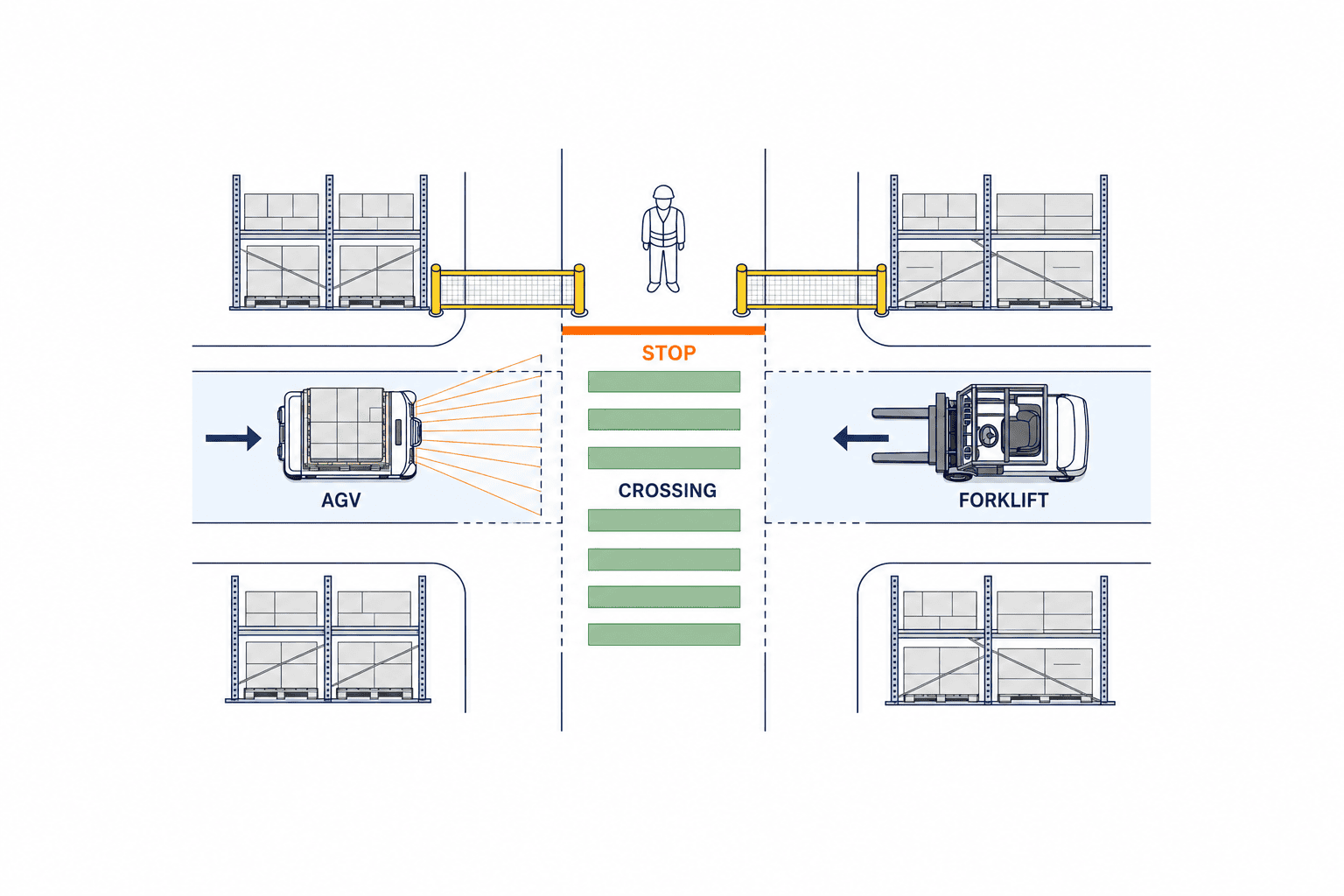
Hierarchy of controls — practical selection in order: Elimination → Engineering controls → Procedures & training
Implement risk-reduction measures in order of priority. Don’t rely on a single measure; combine multiple layers (redundant protective measures) for effective safety.
- Elimination and substitution: Remove hazards from the site where possible. Examples: fully separate pedestrian traffic from AGV routes, physically separate forklift routes, eliminate dangerous temporary routes. This is the most effective measure.
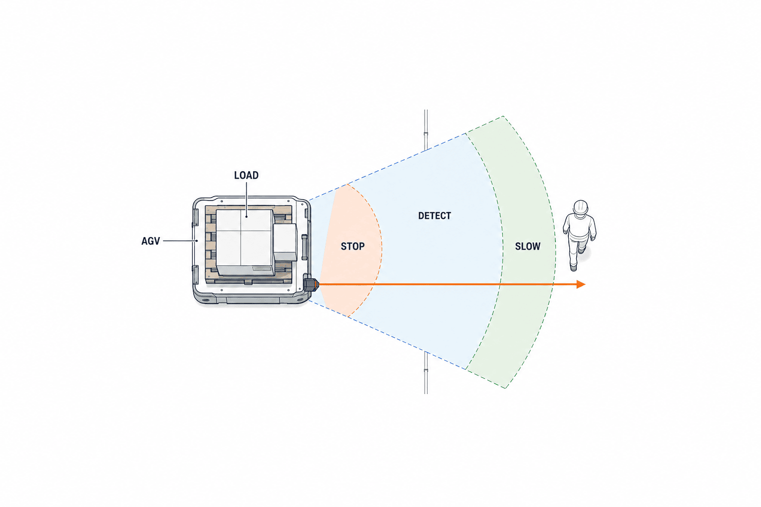
- Engineering controls: When elimination is impractical, control by design. Physical barriers, guardrails, convex mirrors, fixed cameras for blind spots, floor-friction improvements and anti-slip coatings. On the vehicle side, implement sensor suites, safety-related control, automatic speed profiles, and zone control (slow → stop → safety confirmation) according to the risk assessment. Align these solutions with design principles from ISO 13849-1:2023 and relevant IEC standards.
- Administrative controls and training: Access control, signage, operating procedures, emergency response procedures, maintenance schedules, crossing priority rules, and approval processes for temporary routes. Make procedures concise and practically executable, and conduct periodic drills.
- Personal protective equipment (PPE) and warnings: The lowest layer — safety shoes, high-visibility vests and personal alarms. PPE depends on human behavior and should not be the sole control.
Practical guidance: Prefer physical separation when feasible; cover difficult sections with engineering controls and reduce residual risk through procedures and training. Evaluate all controls per ISO 12100 risk-reduction principles and document that residual risk is within acceptable limits.
How to design and verify AGV stop/detection zones
Designing stop and detection zones depends on vehicle hardware performance plus load, floor state, slope, sensor condition, network delays and control algorithms. The following is a practical guide for site design; final decisions must follow site risk assessment and manufacturer instructions.
- Understand response latency: The time from detection to the control system issuing a brake command and the physical start of deceleration differs by vehicle. Require the vendor to provide in writing the “maximum latency from detection to brake actuation” and set safety margins accordingly. Latency includes software communication delay, sensor filtering, and motor drive response.
- Consider braking performance (maximum load, slope, and worn floors): Stopping distance tends to be longest at maximum load, specified slope, and on worn/wet floors. Manufacturer-provided stopping characteristics are reference values; on-site verification (brake tests under worst conditions) is mandatory. Use “worst-case verification” to confirm stopping motion falls into the target safety area. This determines design speed and monitoring zone widths.
- Edge detection and protruding loads: Pallet or load protrusions may contact obstacles outside the vehicle’s sensor coverage. Implement load-dimension control and “protrusion inspections” or add vehicle-side sensors (side sensors). For expected protrusions, include a pre-entry check zone (load-check stop).
- Zone configuration and transitions: Divide travel paths into multiple safety zones (for example: remote monitoring zone → approach slow zone → stop-confirmation zone) and define operation modes per zone. State transitions during zone switching (sensor changes, velocity targets update) are sequential and can incur delay; provide redundant safety boundaries to account for this. Require interlocks between zones so that any inconsistency during switching results in a safe stop.
- Sensor redundancy and fail-safe behavior: Design safety functions and fault-detection/stop behavior so that sensor failures do not allow hazardous motion. Simply adding navigation cameras or ultrasonic sensors does not prove redundancy for safety functions. Specify how redundancy is handled on faults (automatic speed reduction → stop → operator notification, etc.).
- Communication delay and network loss measures: Where communication is required for zone switching or multi-vehicle coordination, explicitly state fail-safes for communication loss. Verify that required safety stops occur independently of communication status and provide evidence.
- Physical verification and periodic re-evaluation: Always verify design values through on-site testing and schedule periodic re-evaluations. Zone widths and deceleration requirements change as floor conditions, load types or operating rules change. Formalize annual reviews and ad hoc reviews for layout changes.
- Example verification procedures (practical checklist): Stopping tests with maximum and minimum payload, wet-floor and oil-contamination simulation tests, sensor detection trials at blind corners, communication delay tests during zone switching, and interlock verification in manual rescue scenarios. Record these verification results for traceability and include acceptance criteria in the procurement contract.
Design note: The above are design guidelines; fixed values for stopping distance or speed vary by site. Finalize these parameters by on-site measurement and manufacturer tuning. For travel-space design, refer to the AGV layout design article: AGV layout design article.
Handshake, Deadlock, Safe States and Responsibility Boundaries at Fixed Interfaces (Conveyors / Doors / Lifts)
Scenarios where AGVs (automated guided/automated mobile vehicles) interact with fixed equipment inside a factory—loading/unloading to/from conveyors, door opening/closing, lift operation—are areas where vehicle and equipment movements overlap and therefore require specific consideration for crushing, entrapment, and load collapse. Safety design must assume “coordination between machines” and combine technical handshakes with physical fail‑safe measures, while each stakeholder (AGV vendor, fixed‑equipment supplier, factory operations/maintenance owner) clearly allocates responsibilities. Final parameters (stop distance, sensor positions, timeout values, etc.) must be determined based on site‑specific risk assessment and vendor instructions. Do not treat standards cited here as legal requirements; they are normative references (see ISO 3691‑4:2023, ISO 12100:2010).
- Principle of handshake: a communication‑based handshake should perform mutual state confirmation: both parties exchange confirmations such as “ready to load” or “gate open” before starting the transfer. Protocols should include redundancy (message acknowledgement, retransmission, and timeouts). If communication is lost, the system must transition to a safe stop or a safe wait state. Dispatch/coordination specifications such as VDA5050 are effective for traffic control and optimization, but any safety decision during handshake must always be guaranteed by independent safety mechanisms. In other words, separate optimization/dispatch logic from independent safety functions.
- Deadlock avoidance and resolution: Define priority rules, timeouts and recovery actions where an AGV and fixed equipment wait for each other. Design safety-related interlocks from the risk assessment and verify that dispatch faults cannot cause hazardous motion.
- Defining safe states: formalize a “safe state” for each fixed interface. Examples: if communication is lost at the point when a door should close, stop hazardous motion of both AGV and door; if conveyor loading is not ready, return the AGV to a waiting position; if a lift fails, lock the lift and notify the AGV that loading is not permitted. Visualize safe states (lamps / panel indicators) so operators can take immediate, informed action.
- Clarifying responsibilities: contracts and RFPs must state under which conditions each party will perform safe stop and recovery. Example allocations reduce disputes: “physical hold/locking on door‑mechanisms in the event of failure is the responsibility of the fixed‑equipment supplier” and “processing to cancel a door‑closure action initiated by an AGV is the AGV vendor’s responsibility.” Include function verification and acceptance criteria as part of FAT/SAT.
On the shop floor, integrate these designs and procedures into a Work Flow Diagram and an Interface Responsibility Matrix, and clearly document emergency procedures (escalation routes, contact points, roles).
Alerts and Degraded States (communication loss / scanner occlusion / localization uncertainty / E‑stop reset)
Even during normal operation, AGVs will face various “degraded states.” Handling degraded states is both a design and operational requirement to maintain safety; final decisions must be anchored in the site‑specific risk assessment (refer to ISO 3691‑4:2023, ISO 12100:2010).
- Communication loss (Controller–AGV / AGS–fixed device): upon communication loss there are two common strategies—immediate safe stop, or limited short autonomous operation allowed. Which strategy to adopt depends on the acceptable risk at the site and the surrounding environment, so specify it explicitly. Define timeouts for reconnection, retry counts, and required logging; also define the responsibilities for actions after communication loss → safe stop → recovery operation (manual release vs automatic recovery).
- Scanner (laser / 3D camera, etc.) occlusion: scanners are frequently occluded temporarily by workers or materials. When a detection blind spot appears, the AGV should transition to reduced speed or stop; operational rules must be set in advance (e.g., “if reacquisition occurs while creeping, continue; if not, stop and request operator confirmation”). Where applicable to the selected safeguarding function, evaluate protective distance using ISO 13855:2024 and measured site stopping performance. IEC 61496-3:2025 is relevant to qualifying diffuse-reflection safety laser scanners; do not assume every 3D camera falls within its scope. Verify occlusion behavior and the required safety performance for the complete safety function, rather than the sensor alone.
- Localization uncertainty (SLAM failure, etc.): when an AMR/AGV’s self‑positioning accuracy degrades, there is a risk of route deviation or ingress into hazardous zones. The fleet/traffic management system should monitor localization confidence and transition to reduced speed, stop, or call an operator when confidence drops. Localization confidence thresholds and corresponding procedures must be validated during SAT and recovery must use verified processes (manual re‑referencing or safe automatic reset).
- Emergency-stop reset: Release an emergency stop only after checking the area and through an authorized operator action. Test that releasing it does not itself restart the vehicle; restarting requires a separate deliberate command. ISO 13850:2015 provides general emergency-stop design principles.
Record all alerts and degraded states as time‑series logs and make them analyzable so operations can use them for continuous improvement. Reiterate that alert thresholds and responses are to be decided based on vendor instructions and site risk assessment.
Charging, Battery Management and Coordination with OEM / Fire Teams
Batteries require special management for fire risk, chemical leakage, and electrical incidents. Align equipment tradeoffs (run time vs weight, charging strategy) with site safety measures.
- Charging infrastructure design: place charging stations in a designated area with fire‑resistant separation materials, adequate ventilation, and fire detection/suppression systems per site requirements. AGVs at charge should provide mechanical immobilization and an external power isolation mechanism; an interlock that cuts power immediately on an abnormal condition is recommended. Ensure reliable handshake between charging station and AGV to communicate “charging start / complete / error.”
- Battery safety management: implement handling rules and monitoring appropriate to battery chemistry (Li‑ion, LiFePO4, etc.), including temperature monitoring and cell balance monitoring. Mandatory protections against overcharge, overdischarge and short circuits are required. Save self‑diagnostic logs at pack level and monitor cycle life and degradation to schedule planned replacements.
- Coordination between OEM and fire teams: emergency procedures for charging equipment and batteries should be developed jointly by the OEM (technical data such as MSDS and emergency response guides) and the factory fire/security teams. Prepare battery isolation procedures for fire incidents, confirm compatibility of extinguishing agents (battery fires may not be properly addressed by standard water-based suppression), secure evacuation routes, and provide technical information to responding fire services (battery composition, maximum energy, behavior during power loss). BOI industrial policy information is for investment environment reference; verify separately whether legal procedures or incentives for charging infrastructure apply in your case (see BOI automation guidance).
- Practical coordination items: get the OEM’s “battery abnormality thresholds,” “safe discharge procedures,” and “battery disposal flows,” and incorporate them into factory procedures. Include AGV scenarios in fire drills. Clarify manufacturer warranty scope and factory maintenance responsibilities in contract.
Charging safety only works when both equipment specifications and site procedures are in place. Final battery settings and emergency response shall be decided based on product manuals and site risk assessment.
Verifying AGV Safety Measures in FAT and SAT
Separate functional verification and safety verification between FAT and SAT. FAT confirms function and safety logic at the vendor facility; SAT is an integrated verification under local environment, interfaces and operational conditions. Include negative cases (failures and abnormal conditions) in tests. Define final pass/fail criteria based on the site risk assessment and vendor instructions (refer to ISO 3691‑4:2023 and ISO 13849‑1:2023).
Test items for normal and abnormal cases
– Basic driving performance: verify normal driving under specified payload, floor conditions, slopes and turning conditions. For abnormal cases, safely test response to unacceptable payload inputs or detection of prohibited loading.
– Obstacle detection and stopping: sensors must trigger safe stop. Negative cases: partial sensor occlusion and fail‑safe behavior (creep or stop).
– Interface handshake: verify correct handshake sequences with conveyors, doors and lifts. Negative cases: verify timeout behavior when handshakes fail (retreat and alert).
– Position accuracy / localization: verify within allowed position error. Negative cases: verify behavior when landmarks are lost (stop and notify managers).
– Behavior on communication loss: under communication loss, confirm transition to the safe state defined by risk assessment and specification. On recovery, confirm there is no unintended automatic restart.
– Emergency stop function: confirm designed stop behavior and ensure no restart after reset unless allowed by approved procedure. Simulate circuit faults only following vendor‑approved safe test methods.
– Battery related: verify charging start/stop and over‑temperature alarms using vendor test modes and records. Do not intentionally push real cells into hazardous conditions.
– Software updates and rollback: verify update application, validation, and safe rollback on failure.
– Human interface (UI / alerts): verify operator notifications are accurate and measures against misuse are effective.
Evidence required for acceptance
– For each test, keep test procedures, result records, video recordings, and log files, with responsible person signatures and timestamps. For negative cases, document specific failure modes, time to respond, and corrective actions to prevent recurrence.
– For safety‑related functions, map the product conformity documentation, circuit diagrams, calculations / validation records to the on‑site test results. Do not prescribe a single hardware configuration; confirm required performance based on a risk assessment.
How to proceed on site
– In FAT, confirm functional acceptance criteria while also checking software version control, update procedures, and diagnostic log formats. In SAT, reproduce FAT results under site conditions—validate floor surface, radio environment, and interactions with personnel flows.
– Verify abnormal cases using vendor‑approved safe test methods. For example, use vendor test modes to inject a scanner fault, simulate a communication loss, and confirm the system does not grant entry when a door remains open.
For both FAT and SAT, define approval criteria and corrective actions, and ensure traceability between requirements and test results.

Safety Requirements and Acceptance Evidence to Include in an AGV Procurement RFP
Below are principal items to include in an RFP so suppliers clearly present safety responsibilities and required evidence. Final specification must be confirmed by on‑site evaluation and applicable regulations.
| Item to confirm | Wording to include in RFP | Evidence at acceptance |
|---|---|---|
| Responsibility allocation | Define vehicle, fixed‑equipment and site operations owners and the boundary for stop & recovery actions | Responsibility allocation table, interface specifications |
| Safety documentation | Scope of applicable standards, hazards, residual risk, and operating conditions | Manufacturer documentation, site risk assessment records |
| Load and floor | Permitted payload, center of gravity, overhangs, slopes, steps, and friction conditions | On‑site measurements, stopping test records |
| Detection coverage | Protective fields, occlusion behavior, switching conditions, alarm settings | Configuration files, on‑site verification results |
| Equipment interfaces | Permitted signals and abnormal behavior with doors, conveyors and lifts | I/O diagrams, sequence diagrams, abnormal case test results |
| Updates & maintenance | Software update, recovery, parts replacement, and training procedures | Version history, maintenance plan, training records |
| Change management | Re‑evaluation and re‑testing requirements when routes or load types change | Change requests, re‑acceptance records |
In the RFP, require vendors to state “compliant / non‑compliant” and provide submission deadlines for each item so bidder readiness can be assessed during the tender stage. Weight safety non‑compliance heavily in scoring.
Hypothetical 30/60/90‑day Phased Example (illustrative, not prescriptive)
The following is a typical early deployment timeline example; it can vary widely with factory conditions. Always defer legal and final safety decisions to the site risk assessment and vendor instructions.
- Initial 30 days: installation and baseline setup. Floor inspection and marking, charging station installation, basic network setup, basic function checks in FAT. Provide basic training for on‑site operators.
- Day 60: SAT and limited operations. Operational runs under real loads, interface tests with fixed equipment (handshake), verification of negative cases. Fine‑tune parameters based on log analysis. Run joint drills with fire/security teams.
- Day 90: expanded operation and final approvals. Finalize operating rules, grant conditional full‑time operation, start change management workflow, and set up continuous monitoring.
These are examples only—formal pass criteria and corrective plans should be documented for each phase.
Operations and Change Management: Incident / Near‑miss Logs and Re‑validation Triggers
Sustained safety depends on continuous management after deployment. Without structured change management and incident management, initial safety gains will not last.
- Incident and near‑miss records: log all incidents and near misses with time, location, model, circumstances (photos/videos), parties involved and severity. Regularly review and perform trend analysis (e.g., repeated events at a specific location) and feed corrective measures back into operations.
- Re‑validation triggers: typical triggers for re‑validation include major software version updates, changes to fixed‑equipment interfaces, floor renovations, repeated near misses, increased E‑stop activations, or a serious incident. Define the scope and procedures for re‑validation within the change management process.
- Change management process: submit change requests in writing, perform impact assessments (safety, productivity, schedule), then follow approval → implementation → re‑test → sign‑off workflow. Ensure traceability for every change.
- Continuous training: provide periodic refresher training and onboarding for new staff to reduce misuse and procedural drift. Keep training records and set evaluation criteria.
These are organizational controls that must run in parallel with technical controls to be effective.
Frequently Asked Questions about AGV Safety Measures
What should an AGV do if a scanner is temporarily occluded?
First, the acceptable safe action for occlusion scenarios must be specified in advance (e.g., stop / alarm). If occlusions occur frequently, consider sensor redundancy or relocating sensors. Always validate occlusion behavior during on‑site SAT.
Which is safer, AMR or guided/track AGV?
Choice depends on how often the plant layout changes, layout complexity, budget and maintenance capabilities. AMRs offer flexibility for frequently changing sites; guided AGVs can be appropriate for stable routes. Regardless, verify vehicle safety functions and on‑site protective measures for either type.
Who should perform reset after an emergency stop?
Limit reset authority to trained personnel and institutionalize a two‑step confirmation (site visual confirmation using a checklist + successful AGV self‑diagnostics). If automatic recovery is allowed, require strict conditions and diagnostic checks.
What safety measures when pedestrians and vehicles share aisles?
In shared zones combine speed limits, right‑of‑way rules, improved visibility (colored markings, lighting), and presence detection devices. Validate safety performance through SAT under real pedestrian/vehicle flows.
How much should AGV safety cost?
Costs vary widely depending on equipment configuration, sensor redundancy, software design, FAT/SAT scope, and training volume. Require the RFP to list price items separately so comparisons are possible. Obtain site‑specific estimates.
What are obligations or guidelines specific to Thailand?
Thai industrial or automation policies (e.g., BOI) are useful for investment information but evaluate safety standards and legal liability according to local law and the international standards you adopt. For legal interpretation or application, consult legal counsel or relevant authorities (BOI automation information is a policy reference).
How to decide scanner mounting height and protective distance?
Decide protective distance and mounting height from the maximum intrusion profile of objects/people, sensor detection characteristics, and AGV speed. Confirm protective device selection and standards, refer to ISO 13855:2024 as needed, and set values after on‑site measurement and testing.
How is fleet management different from safety functionality?
Dispatch and fleet management (see: AGV fleet management article) optimize routing and assignment for efficiency. Safety functions such as collision avoidance and emergency stop must be handled by independent vehicle or external safety systems. Treat optimization as support for decision‑making, not as the primary safety authority.
These answers are general guidance. Final decisions must be made based on site risk assessments and vendor technical documentation.
Summary: Linking Site Conditions through to Acceptance Tests
AGV safety requires an integrated design across technical devices (sensors, E‑stops, interlocks) and institutional components (responsibility allocation, RFP, FAT/SAT, change management). Clarify fixed interfaces, degraded states, battery management, test plans, procurement requirements and operational processes, and maintain traceable evidence to ensure both initial and long‑term safe operation. Always let site‑specific risk assessment and vendor instructions drive final decisions.
For help assessing your crossings and hand‑over processes on site, contact TOMAS TECH to review site conditions and procurement and acceptance test points together
References
- ISO 3691-4:2023: Driverless industrial trucks and their systems
- ISO 12100:2010: Machinery risk assessment and risk reduction
- ISO 13849-1:2023: Safety-related control systems
- ISO 13855:2024: Positioning of safeguards
- IEC 62046:2026: Application of protective equipment
- IEC 61496-2:2020: AOPDs, including light curtains
- IEC 61496-3:2025: Diffuse-reflection protective devices
- ANSI/A3 R15.08-1:2020 (R2026): Industrial mobile robots
- Thailand BOI: Automation information


