


Lead: Graphs Alone Cannot Answer “Which Lot Was Affected?”
One day, the Quality Assurance department asked, “There was a temperature deviation in the constant temperature and humidity chamber— which product lots were affected?” In many factories, it is common to believe that presenting time-series graphs of temperature and humidity demonstrates “control,” but graphs alone cannot accurately explain “which lot, during which time period, was exposed to what degree of deviation.” Automating records is not just about “visualization” or PoC (proof of concept); it requires designing a “record system” that allows third parties to review and provide explanations based on evidence later.
Intended Readers and the Boundary Between “Control” and “Monitoring”
This article is intended for leaders in procurement, quality, and engineering departments at factories in Thailand and Japan, especially those considering “automation of temperature and humidity records” and who will be responsible for future audits, complaint handling, and proving product quality. The focus here is not on “temperature and humidity control” or “monitoring,” but on the automation of “records.” Rather than simple real-time monitoring or alarm notification, the emphasis is on designing and operating a record system that can be “explained retrospectively.”
Starting Point for Record Design: “What Quality Questions Must Be Answered?”
The design of automated temperature and humidity records should begin with the question, “What quality-related questions must be answered?” For example:
- “How many minutes was this lot exposed to temperatures outside the specified range?”
- “When a deviation occurred, who responded and how?”
- “Which sensor, and in what calibration state, was this data obtained from?”
It is essential to design the system so that these questions can be answered later, based on “records.” It is not enough to simply list graphs or numbers; it must be possible to trace the “context” and “origin” of the records.
Minimum Record Schema: What Must Be Recorded?
For automated temperature and humidity records, the minimum required record items (schema) are as follows. Omitting any of these will make it impossible to withstand later explanations or audits.
- Source Sensor ID: Which sensor the data was obtained from
- Equipment/Zone ID: Which room, equipment, or area
- Measurement Value & Unit: Temperature, humidity, and unit
- Source Timestamp: Time recorded by the sensor
- Reception Timestamp: Time the system received the data
- Status/Quality Code: Communication errors, calibration expired, abnormal values, etc.
- Calibration State/Version: Calibration certificate number and expiration date at the time of acquisition
- Applicable Limit Version: Which management standard (e.g., SOP version) should be used for evaluation
- Lot/Work Order Link: Which product lot or work order the record is linked to
- Alarm/Action ID: Alarm ID or response record ID when a deviation occurs
- Ingestion ID: Identifier for the data ingestion process (for retransmission/deduplication)
This schema aligns with the OPC UA historical data specifications (OPC Foundation Historical Timestamps, StatusCode, Original Values), as well as the FDA’s data integrity guidance Reference 10.
Record Example: Sample Table of a Deviation Event
Below is an example record when a temperature deviation occurred in a constant temperature and humidity chamber. The values and IDs are fictitious for explanatory purposes and do not represent universal thresholds or standards.
| Source Sensor ID | Equipment/Zone ID | Value | Unit | Source TS | Reception TS | Status | Calibration Cert No. | Calibration Expiry | Management Standard Ver | Lot ID | Work Order ID | Alarm ID | Action ID | Ingestion ID |
|---|---|---|---|---|---|---|---|---|---|---|---|---|---|---|
| S-001 | CHAMBER-1 | 27.5 | ℃ | 2024-06-01T14:02:00+07:00 | 2024-06-01T14:02:03+07:00 | OK | CAL-2024-05-01 | 2025-05-01 | SOP-2024-04 | LOT-20240601-A | WO-20240601-01 | ALM-001 | ACT-001 | ING-0001 |
| S-001 | CHAMBER-1 | 28.3 | ℃ | 2024-06-01T14:07:00+07:00 | 2024-06-01T14:07:04+07:00 | OVER | CAL-2024-05-01 | 2025-05-01 | SOP-2024-04 | LOT-20240601-A | WO-20240601-01 | ALM-002 | ACT-002 | ING-0002 |
| S-001 | CHAMBER-1 | 27.2 | ℃ | 2024-06-01T14:12:00+07:00 | 2024-06-01T14:12:03+07:00 | OK | CAL-2024-05-01 | 2025-05-01 | SOP-2024-04 | LOT-20240601-A | WO-20240601-01 | ING-0003 |
As shown, by recording alarm IDs and response records (action IDs) at the time of deviation, calibration information, management standard version, and links to lot/work order, it becomes possible to later explain “which lot was exposed to which deviation and how it was handled.”
Sensor Installation Locations and Calibration Chain: The Reality of NIST Traceability
Considerations for Sensor Placement
Sensor placement must be carefully determined according to product and process risk. For example, within a constant temperature and humidity chamber, it may be recommended to install sensors at multiple points such as “near the actual product,” “the location with the greatest temperature fluctuation,” and “an independent system separate from the control sensor” (Vaisala Temperature Mapping Discussion). In Thai factories, it is also necessary to verify the representativeness of measurements at entrances, air conditioning outlets, and near exterior walls, and to document the reasons for installation in each zone.
Calibration Chain and NIST Traceability
Sensor calibration may sometimes require traceability to national standards such as NIST (National Institute of Standards and Technology, USA). However, NIST traceability does not mean that the certificate is directly linked to NIST; rather, the essence is that the calibration chain is documented (NIST Metrological Traceability). During the design phase, confirm the method for recording the measurement range, uncertainty, and certificate details of the calibration service provider used domestically in Thailand, as well as the certificate number and expiration date.
Zone and Climatic Operational Differences in Thai Factories
In Thai factories, it is important to check the rainy and dry seasons, outside air inflow, and air conditioning operating conditions for each installation location. Each zone may have different risk points, such as “walls facing outside air,” “high temperature and humidity areas,” and “directly under air conditioning.” It is essential not to simply copy Japanese factory designs, but to design zones based on local climate, building structure, and actual operations.
System Architecture: From Sensor to Record and Review
An automated temperature and humidity recording system requires more than just sensors and graph displays. A multi-layered structure as follows is necessary:
- Sensor/Logger
Manages installation location and calibration state, records measurement values and timestamps.
- Gateway
Collects data from sensors, manages communication errors, deduplication, and time synchronization.
- Historian (Record DB)
Stores all records with schema, supports later search and review.
- Review Interface
Enables record search, response recording for alarms, reference to calibration certificates, and provides a user-friendly UI for audit and quality departments.
- QMS/MES Integration
Links with lot, work order, and deviation response records for unified quality record management.

Limitations of OPC UA and Metadata Assurance
The OPC UA Historical Access specification defines methods for handling timestamps, status codes, original values, and change history (OPC UA Historical Timestamps, StatusCode, Original Values). However, not all metadata is automatically guaranteed. For example, calibration certificate numbers, lot IDs, and action IDs cannot be ensured by OPC UA alone unless an explicit mechanism for recording and linking them is established during system design.
Time Zones, Timestamps, and Clock Drift
Handling Source/Server Timestamps
Both the “source timestamp” recorded by the sensor itself and the “reception timestamp” assigned by the gateway or historian upon receipt must always be recorded. In reality, there are many cases where the actual measurement time and the record time do not match due to network delays, buffering, sensor clock drift, or delayed transmission after temporary communication loss (OPC UA Historical Timestamps).
Explicit Time Zone Indication
In Thai factories, records are generally kept in Thai time (UTC+7), but if servers or cloud systems operate in Japan time (UTC+9) or UTC, it is essential to explicitly indicate the time zone in timestamps. Without specifying the time zone, it becomes impossible to accurately explain later “when the deviation occurred” or “which lot was affected.”
Handling Clock Drift and Delayed Delivery
If the clocks of sensors or gateways are out of sync, the reliability of records is compromised. It is necessary to implement periodic time synchronization (e.g., NTP), detection and recording of clock drift, and recording both “actual measurement time” and “reception time” in the case of delayed delivery, as part of the design phase.
Main Checkpoints During Design Review
- Is the record schema sufficient to answer quality questions later?
- Is it easy to record and reference calibration certificates and management standard versions?
- Is linking with lot and work order automated?
- Is management of timestamps, time zones, and clock drift adequate?
- Does the design compensate for the limitations of OPC UA and other protocols?
- Does installation and operation reflect zone and climate risks unique to Thai factories?
(Continued in PART B)
Missing Data and Backfill Strategies
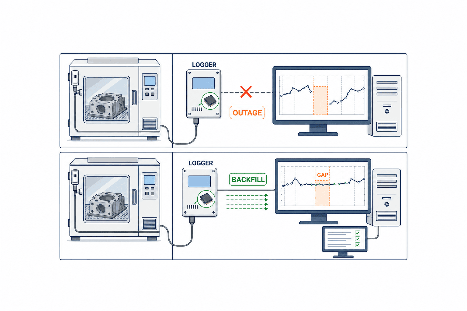
In the automation of temperature and humidity recording, missing data is an unavoidable risk. On the factory floor, a variety of factors such as network failures, sensor malfunctions, and power outages can interrupt data logging. To ensure the completeness of records, it is necessary to clearly design policies for handling missing data and to select operational methods according to process and product risk.
If the logger is configured to retain measured values during network failures and transmit them after recovery, missing data can be reduced. However, according to the OPC UA Historical Access specification alone, late-arriving data is not automatically identified as “backfill.” In some cases, data that is initially bulk-inserted with past source timestamps may not generate change records (OPC Foundation historical updates and original values). Therefore, in addition to the measurement and receipt timestamps, application-specific flags for delayed arrival or retransmission, as well as the original event ID, should be defined as requirements. During acceptance testing from communication outage to recovery, it must be confirmed that these are retained in display and export.
On the other hand, if field devices or systems do not have a local buffer, data during network outages becomes physically unobtainable and remains as a “gap” in the record. In this case, explicitly recording the missing interval (for example, with a “No Data” flag or a blank with a reason) is essential for later audits and quality assessments. Rather than pretending the data never existed, accurately recording the fact and period of missing data maintains the reliability of process risk assessments and lot determinations.
Differences Between Invalid Values, Missing Data, Interpolated, and Raw Data, and OPC UA-Based Evidence
In automated temperature and humidity recording, it is important not only to collect values but also to clearly distinguish “what kind of value” each is. The OPC UA Historical Data Model allows each data point to be assigned a “StatusCode,” recording the validity and origin of the value (OPC Foundation historical StatusCode).
- Invalid values: Values determined to be unusable for quality assessment, such as those resulting from sensor malfunctions, are treated as invalid along with their causes. When using OPC UA StatusCodes such as Bad, confirm which device applies them and under what conditions.
- No Data: For intervals where there are physically no measured values, do not fill in as if values existed. Design should distinguish between NoData responses at readout and missing data events stored by the application.
- Interpolated values: Values estimated from preceding and following values must be distinguished from measured values. In OPC UA’s ReadAtTime, there is a specification to indicate Interpolated in InfoBits when interpolation occurs (OPC Foundation raw vs interpolated readings).
- Raw data: When original recorded values exist at the specified time, the same ReadAtTime specification indicates Raw in InfoBits. Note that Raw and Good have different meanings; do not assume that raw data is always Good.
This distinction is essential when reviewing records later, investigating deviations, or proving regulatory compliance. For example, if a temperature or humidity deviation occurs during a process, whether the value at that time is “raw data” or “interpolated” can greatly affect the quality department’s judgment and lot handling.
Simulation of Network Outages and Local Buffer
The robustness of data recording during network outages is a critical evaluation point in system design. For example, some systems such as Vaisala viewLinc implement a function where sensors or local units internally store data during network failures and automatically upload it to the server after recovery (Vaisala viewLinc official product). In this case, data gaps are minimized and record continuity is maintained.
However, not all systems guarantee this function. Before implementation, it is essential to conduct tests simulating actual network outages to confirm system behavior. If there is no local buffer and data during the outage is completely lost, it is safer from a risk management perspective to leave an explicit gap in the record and not perform interpolation or estimation afterward. Relying on interpolated values increases the risk of overlooking actual deviations or abnormalities.
Original Records, Corrections, Operator/Reason, and Audit Trail
For temperature and humidity records, preservation of the original record and traceability of corrections are defined as requirements. OPC UA Historical Access specifies mechanisms for handling changed values, original values, and change information, but implementation and storage of history management and audit events must be verified for each adopted product and configuration. In particular, for initial bulk insertion of data with past timestamps, change records may not be created (OPC Foundation historical updates and original values). Therefore, the application should record pre- and post-correction values, responsible personnel, timestamps, and reasons, and verify whether reconstruction is possible even after export.
For example, when a field operator corrects data after sensor replacement or calibration, it is required to record who made the correction, when, what value was changed, and for what reason, leaving this as an audit trail. This enables later quality audits and traceability requirements to be met. Recording the reason for correction is not just an operation log, but serves as evidence for process risk and product quality impact assessments.
Furthermore, even if corrections or additions occur, it is important not to physically erase the original record, but to centrally manage both the pre- and post-correction values and reasons. This enables early detection of intentional tampering or operational mistakes and fulfills accountability during audits.
Alarm Thresholds, Version Control, Approval, Corrective Action, and Closure
In alarm management for temperature and humidity deviations, setting thresholds and managing their versions is important. By setting different thresholds for each process or product and recording their change history, it is possible to clarify which criteria were applied at which point in time.
When an alarm occurs, it is necessary to distinguish between “acknowledgement,” “corrective action,” and “closure.” The OPC UA alarm model allows operators to perform an “acknowledge” operation when an alarm occurs and to record this (OPC Foundation alarm acknowledge method). However, acknowledgement is merely a record of recognition, and whether actual corrective action (such as on-site inspection or equipment adjustment) has been completed must be managed separately.
It is recommended that records of corrective actions include the responder, action details, date and time, root cause analysis, and recurrence prevention measures. By centrally managing these and having the quality department or responsible person perform the final “closure” operation, the completion of alarm response can be clearly defined. Combined with version-controlled threshold information, it is possible to accurately review later which criteria were in effect when the deviation occurred and what actions were taken.
Escalation Between Shifts
In factories operating 24 hours a day, it is common for alarm responses and record reviews to span across shifts. There are many cases where an alarm occurs but cannot be addressed during the night shift and is escalated to the day shift. Automated recording systems must clearly indicate the “incomplete” status of alarms and corrective actions and provide a mechanism to reliably hand over to the next person during shift changes.
For example, if there is no response within a certain time after an alarm occurs, the system can automatically notify a higher-level person, or automatically display a list of unresolved alarms at shift change. The presence and operational design of escalation functions are directly linked to reducing quality risks. When designing the system, it is important to confirm whether escalation rules can be flexibly set, taking into account actual field operations and staffing.
“`
+——————-+——————-+——————-+
| Record Type | Example | OPC UA Status |
+——————-+——————-+——————-+
| Raw Data | 23.5°C, 55%RH | Good |
| Invalid Value | Sensor failure | Bad |
| Missing Data | Network outage | No Data |
| Interpolated | Estimated between | Interpolated |
| | two points | |
+——————-+——————-+——————-+
“`
Humidity Deviation Scenarios During Production and Overlapping Lot Boundaries
As a concrete operational example, consider a case where humidity temporarily exceeds the upper limit during the production of a certain product. For instance, if production of Lot A ends and production of Lot B begins immediately after, and a humidity deviation occurs at this timing, the deviation period overlaps the boundary between the two lots. In such cases, it is necessary to strictly identify which lots were affected.
A conservative policy in the quality department recommends placing all lots corresponding to the deviation period on “hold,” and making a “release” decision after additional quality evaluation or re-inspection. What is important here is that the reliability of the judgment changes significantly depending on whether the record is “raw data” or includes “interpolated” or “missing” intervals. For example, if a network outage overlaps the deviation period and some data is “missing,” stricter hold measures may be required.
In such scenarios, the completeness and clarity of the record’s origin serve as the basis for quality decisions. Whether the record during the deviation is continuous “raw data” or a mix of interpolated and missing data greatly affects the final lot release decision and the level of accountability to customers.
Security Roles, Supplier Remote Access, Backup & Restore, Export & Replay Testing, Retention Period
In automated temperature and humidity recording systems, permissions for viewing, alarm confirmation, correction, configuration changes, and backup are defined by job role. OPC UA provides mechanisms for roles and auditing, but whether the server implements all or part of the role mechanism depends on the product, and disk storage of audit events is not guaranteed by the specification alone (OPC Foundation OPC UA security model). For each test account—field, quality, maintenance, IT/OT—verify which operations are permitted or denied, and make the implementation of audit log storage location, retention period, backup, and tamper detection acceptance criteria.
Additionally, even when remote access by suppliers is necessary, it is recommended to limit the scope and permissions of access and always keep access logs. Operation records during remote maintenance should also be managed as part of the audit trail.
Backup and restore functions are indispensable for record preservation in the event of failures. By incorporating regular backups and post-restore data integrity verification (such as replay testing of exported data) into operational procedures, the risk of data loss can be minimized. Export functions allow record data to be output in formats such as CSV or PDF for use in external audits or customer submissions, but it is important to clearly indicate the origin of the data (raw, interpolated, missing intervals) at the time of output.
The retention period for records is defined individually according to customer requirements and process/product risk. For example, pharmaceuticals or high-reliability components may require long-term storage for several years, but there is not a uniform legal obligation across all industries. Retention period settings should be determined based on the product lifecycle, customer contracts, and internal quality policies, and it is recommended to use system-side automatic deletion or archiving functions to balance operational burden and risk.
In the next PART C, we will further explore on-site challenges during implementation and operation, design points for each process and product risk, and practical operational examples for review and audit.
RFP Specification Template: 12 Practical Questions
When considering the implementation of an automated temperature and humidity recording system, it is crucial that your RFP (Request for Proposal) includes not just specifications or dashboard aesthetics, but concrete requirements from the perspective of actual operations, audits, and quality assurance. The following 12 items are practical questions you must confirm with vendors to ensure risk management and record integrity on the shop floor.
- How are timestamps for recorded data obtained and what is their accuracy?
Does the system use the sensor’s local time, server time, or OPC UA timestamp (Ref. 1)? How are time discrepancies corrected and recorded?
- How are data change histories and audit trails managed?
If recorded values are modified, deleted, or re-entered, is there a mechanism to record who, when, why, and how the changes were made, and to review them later (Ref. 3)?
- What is the response flow when abnormal values or alarms occur?
How are alarms notified, how are they acknowledged, and is there a record of who responded and when (6)?
- How is data preserved during sensor disconnection or communication loss?
What are the methods for recording and recovering data when sensors or networks are temporarily disconnected, resulting in missing or delayed data?
- How are delayed or buffered data identified and recorded?
When a sensor reconnects, does an application-specific flag distinguish late-arriving data from real-time values? Can the value-quality StatusCode be reviewed separately (Ref. 2)?
- How are calibration histories and invalid calibrations handled?
Is there a system for managing calibration work histories, and does it automatically reject or alert if calibration values are outside the specified range?
- How are alarm threshold (setpoint) changes tracked and rolled back?
Is there a record of who changed the threshold, when, and why, and are there procedures to restore previous settings in case of misconfiguration?
- How is the integrity of regenerated CSV/PDF reports ensured?
When reports are regenerated from past recorded data for audits or lot tracing, is there a guarantee that they match the original data?
- Is there a function for searching and extracting data by lot or product?
Can temperature and humidity records linked to specific manufacturing lots or products be quickly extracted?
- How is data consistency ensured during system failures or restarts?
After recovery from server or network failures, is the system designed to prevent data loss or duplicate records?
- How are user permissions and operation logs managed?
Are detailed logs of who performed which operations kept, and are there operation restrictions by permission level?
- How is metrological traceability ensured?
How are sensor calibration certificates and traceability chains managed (Ref. 9)?
These questions are not just for “temperature and humidity monitoring,” but are concrete requirements to achieve “complete and reviewable records.” Be sure to compare vendor responses and confirm that they meet your site’s risk and audit requirements.
Vendor Proposal Comparison: Evaluation Using Sample Data Sets and Demos
Many vendors emphasize dashboard design and attractive graph displays, but the integrity of records and the ability to handle operational troubles cannot be judged by appearance alone. The following approaches are effective for comparative verification after receiving RFP responses.
Verification Using Sample Data Sets
- Provide raw data obtained from actual temperature and humidity sensors (including missing, abnormal, and delayed values), and have each vendor’s system import, record, and generate reports.
- Include scenarios such as intentional sensor disconnection, time discrepancies, alarm occurrence, and recovery to compare how each system records, displays, and leaves audit trails.
Hands-on Operation in Demo Environments
- Have vendor representatives demonstrate the entire process from alarm occurrence to response, record correction, and report regeneration to check operability, audit trails, and data consistency.
- Be sure to check the behavior when switching user permissions and during intentional erroneous or unauthorized operations.
Through such verification, you can determine whether the system ensures not just “monitoring” but also “record integrity and auditability.” For more details, refer to “Key Points for Selecting Temperature and Humidity Monitoring Systems (Thailand Factory 2026 Edition).”
FAT/SAT Detailed Test Cases
During system implementation, it is essential to design and verify detailed test cases in FAT (Factory Acceptance Test) and SAT (Site Acceptance Test) that anticipate on-site risks.
1. Sensor Disconnection and Reconnection
- Physically disconnect and reconnect sensors; verify that the missing interval, late-arrival flag, original measurement time and receipt time are retained after recovery.
2. Timestamp Discrepancies and Correction
- Intentionally shift the sensor’s clock and check the consistency with the server’s recorded timestamp and the recording of correction history (Ref. 1).
3. Handling of Delayed and Buffered Data
- Test whether values received after an outage can be recorded and searched as late arrivals. Separately verify the distinction between raw and interpolated values (Ref. 12).
4. Alarm Occurrence and Acknowledgement
- Trigger alarms by exceeding thresholds, perform user alarm acknowledgement operations, and verify that the history is recorded (6).
5. Record Value Changes and Audit Trails
- Perform record value modification and deletion operations, and verify that pre- and post-change values, responsible personnel, reasons, and timestamps are retained as audit trails.
6. Rejection of Invalid Calibration Values
- During calibration, input out-of-spec values and verify that the system automatically rejects them and issues an alert.
7. Data Consistency After Network Failure and Recovery
- Forcefully stop and restart the server or network, and check for data loss or duplicate records.
8. Regeneration of CSV/PDF Reports and Lot Search
- Regenerate reports for arbitrary periods or lots and verify that they match the original data and can be proven during audits.
9. Threshold Changes and Rollback
- Change and misconfigure thresholds, then perform restoration operations and verify that the history is recorded.
10. User Permissions and Operation Logs
- Confirm that operation restrictions by permission level function correctly and that all operations are logged.
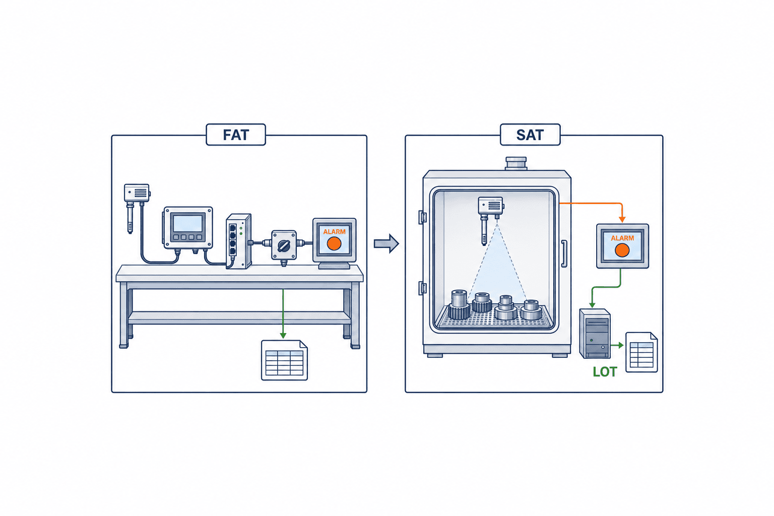
(Figure 3: List of Key Test Cases for Automated Temperature and Humidity Recording Systems to Verify in FAT/SAT)
It is important that all these test cases are comprehensively executed and that all records, audit trails, and report reproducibility are jointly confirmed by the site, quality assurance, and IT departments. For more details on data recording mechanisms, refer to “Practical Points for Measurement Instrument Data Recording (Thailand Factory 2026 Edition).”
Ownership/RACI, Change Management, Calibration/Replacement, Threshold Updates and Rollback
Clarifying Ownership/RACI
Operation of automated temperature and humidity recording systems involves multiple departments, including production, quality assurance, IT, and maintenance. Use a RACI (Responsible, Accountable, Consulted, Informed) matrix to clarify role assignments as follows:
- Responsible: Daily inspections and alarm response (site personnel)
- Accountable: Record integrity and audit response (quality assurance department)
- Consulted: System configuration and troubleshooting (IT and maintenance departments)
- Informed: Management and audit staff
Change Management, Calibration, and Replacement
- Recording Calibration and Replacement: Centrally manage sensor calibration and replacement histories in the system, and link calibration certificates and traceability information (Ref. 9).
- Threshold Updates and Rollback: Always record alarm threshold changes, and establish operational procedures to immediately restore previous settings in case of misconfiguration.
Change Management During Operation
- When changing system settings or performing software updates, it is recommended to always record the change details, responsible person, reason, and date/time, and to establish a pre-approval workflow.
Implementation Phases, Acceptance Criteria, and Key Points to Confirm with Suppliers
Implementation Phases
- Requirements Definition and RFP Creation: Document site risks and audit requirements
- Vendor Selection and Demo Verification: Compare using sample data and live demos
- FAT/SAT: Verification using detailed test cases
- Site Deployment and Training: Operator training and establishment of operational procedures
- Go-live and Operational Audit: Regular record review and audit response
Acceptance Criteria
- All FAT/SAT test cases are passed
- Record, audit trail, and report reproducibility are ensured
- Data consistency is maintained in all operational scenarios, including calibration, threshold changes, and failure recovery
- User permissions and operation logs are properly managed
Key Points to Confirm with Suppliers
- Support structure and recovery procedures in case of system failures
- Methods for managing calibration certificates and traceability
- Change management and advance notification for software updates
- Data preservation and backup structure for long-term operation
Data Dictionary and Boundary Conditions to Define Before Implementation
If you plan to expand data linkage to downstream processes, define not only measurement point names but also immutable identifiers and display names separately. For example, even if the display name of a storage room is changed during site improvement, keep a history linking equipment ID, zone ID, and sensor ID so that past records do not appear as different measurement points. After a sensor is replaced, switch to the new sensor ID from that date, and when referencing the same zone’s time series, indicate the replacement boundary. Also distinguish which values are physical measurements and which are calculated for display. If you do not provide such a dictionary at procurement, each vendor may use different ID granularity or unit notation, making it impossible to integrate lot searches later.
Also clarify where records are generated. Depending on whether the sensor has a measurement timestamp, the data logger assigns it upon receipt, or the gateway upon import, the meaning of the “timestamp” field changes. To later overlay lot dwell times, specify in the requirements how clocks are synchronized, how time accuracy and drift are monitored, and how periods with known drift are handled. OPC UA provides both source and server timestamps, but not all devices store both. Take sample records of your chosen configuration during FAT and confirm which timestamp indicates the measurement event.
Do not determine lot linkage based only on “being in the same minute.” Confirm whether you can capture events such as warehouse entry and exit, loading and unloading into equipment, and pausing and resuming work instructions. If boundary timestamps are missing, you lose the basis to narrow the impact range. Quality staff should set a conservative provisional range and establish procedures to confirm with site records later, to avoid the system mistakenly judging something as safe. Since measurement results and lot events may exist in separate systems, it is important not only to have a query screen but also to be able to return to the original records in both systems.
Test Records to Leave as Acceptance Evidence
FAT test procedures should record not only operations and expected results but also the configuration at the time of execution. Record sensor model and firmware, gateway and server versions, time settings, connection methods, test account permissions, and threshold versions. Even for the same “disconnect the network” test, results differ depending on whether the disconnection is between the sensor and gateway or between the gateway and server. Since screenshots of the test alone make it difficult to explain consistency with the original data, keep the test event ID, export files, and operation logs together.
SAT tests actual buildings and operations. Confirm whether sensors are installed in the planned locations, whether equipment names match the display on the screen, and whether alarms are not left unattended during normal shift handovers. In the event of communication failures, demonstrate how the site is notified of abnormalities, what information is passed to recovery personnel, and who reviews the missing data period later. Acceptance should not end with “the value appeared on the screen,” but require that, for specified lots and periods, another person can reconstruct the original values, abnormalities, responses, and calibration status.
Even after going live, operations such as removing measurement points for calibration, replacing sensors, or changing thresholds alter the context of records. Change forms should include the reason, approver, application time, affected equipment/product range, pre- and post-change settings, and recovery procedures. Even if audit trails exist in software, the chain of explanation is broken if not linked to paper records of on-site work. Define in procedures which records are kept by quality, maintenance, IT/OT, and production, and periodically select and trace an actual event to ensure traceability.
FAQ (Frequently Asked Questions and Answers)
Q1. What is the difference between a temperature/humidity monitoring system and an automated recording system?
A. Monitoring systems are mainly for real-time status awareness, while automated recording systems fundamentally differ in that they completely retain, with audit trails, “who, when, and how” records, modifications, and responses were made, allowing for later review and proof.
Q2. Is it necessary to comply with FDA data integrity requirements?
A. The referenced FDA data integrity guidance applies to US drug CGMP. Applicable laws, contracts, and customer requirements must be confirmed for each product and business partner. The audit trail concepts introduced here are not legal obligations for all Thai factories.
Q3. How is record consistency ensured during sensor calibration or replacement?
A. By centrally managing calibration and replacement histories in the system and linking calibration certificates and traceability information (Ref. 9), you can prove the validity of records during audits.
Q4. How can tampering or erroneous operations on recorded data be detected?
A. All record modifications and deletions must leave audit trails of the responsible person, reason, and timestamp, enabling later review and traceability (Ref. 3).
Q5. What happens to records if a system failure or network outage occurs?
A. If the selected device supports local storage and retransmission, it is possible to identify delayed data after recovery. If not, missing data should be clearly indicated, and operations should not fill gaps with estimated values. FAT/SAT should verify the actual device and network configuration.
Summary & Contact TOMAS TECH
Selecting and implementing an automated temperature and humidity recording system requires a shift from simple “monitoring” to “complete and reviewable records.” To achieve a design and operation that withstands site risks and quality audits, it is essential to clarify practical requirements from the RFP stage and rigorously compare and verify vendor proposals using sample data and live demos.
When consulting TOMAS TECH, please share your target process, current sensors, sample records, lot information location, and expected procurement timing. We can help organize requirements and discuss key points for connection and operation to confirm on-site.
For detailed consultations, on-site hearings, or demo requests, please feel free to contact us via the TOMAS TECH inquiry form.
References
- https://reference.opcfoundation.org/specs/OPC-10000-11/4.5
- https://reference.opcfoundation.org/specs/OPC-10000-11/6
- https://reference.opcfoundation.org/specs/OPC-10000-11/4.4
- https://reference.opcfoundation.org/specs/OPC-10000-9/5.7.3
- https://www.vaisala.com/en/products/software/viewlinc
- https://docs.vaisala.com/r/M212315EN-C/en-US/GUID-E738FA55-CB57-4BE6-8331-C811E10AB988/GUID-46424254-8FC3-4883-AEA9-2946CD88252F/GUID-8A1D9588-D668-45FD-8662-C7F01317869A
- https://www.vaisala.com/sites/default/files/documents/viewLinc-Continuous-Monitoring-System-Brochure-B211555EN.pdf
- https://www.vaisala.com/en/blog/2023-07/temperature-mapping-study-design-duration-intervals
- https://www.nist.gov/metrology/metrological-traceability
- https://www.fda.gov/regulatory-information/search-fda-guidance-documents/data-integrity-and-compliance-drug-cgmp-questions-and-answers
- https://reference.opcfoundation.org/specs/OPC-10000-2/4
- https://reference.opcfoundation.org/specs/OPC-10000-11/6.5.5.2


