


A clamp-on ultrasonic flow meter can add a measurement point to an existing line without cutting the pipe. That advantage is especially useful when a Thai factory cannot easily stop cooling-water or utility service. Successful selection still depends on the liquid, pipe wall and lining, full-pipe condition, straight run, required performance, and intended use of the data. This guide takes engineering, maintenance, and procurement teams from the first site survey through vendor comparison, RFP, FAT, SAT, and long-term operation.
Define the decision the measurement will support
“We need flow data” is not a complete specification. A cooling-pump alarm, water-use allocation, night-flow leak detection, and confirmation of chemical dosing each require a different range, update rate, output, and acceptance test. Write one sentence that names the pipe, operating states, and decision. For example, monitoring falling cooling-water circulation at night calls for stable low-flow readings and a well-defined alarm delay. Monthly water allocation calls for reliable totalization, time synchronization, and a rule for missing records.
Do not transplant a catalog accuracy or range claim to every plant pipe. Performance depends on the specific transmitter and transducer configuration, liquid, pipe, installation, and flow profile. Siemens says a final flow-range determination for SITRANS FS220 requires an application review. Start procurement with site conditions and acceptance criteria, then select a model. Siemens product information
Specify outputs as well as the display
Decide whether an operator will read instantaneous flow locally, the PLC will control a pump, or SCADA/MES will retain the history. Record engineering units, bidirectional-flow sign, totalizer reset permission, what to show on an instrument fault, and what the system should do on a communications failure. A 4–20 mA output may fit an existing PLC analog card; a digital protocol such as Modbus may be useful when totalizers and diagnostics are also required. KROHNE lists 4–20 mA, HART, Modbus, and other options for OPTISONIC 6300, but the selected model configuration must be checked for the combination actually needed. KROHNE product information
How clamp-on measurement works—and where it can fail
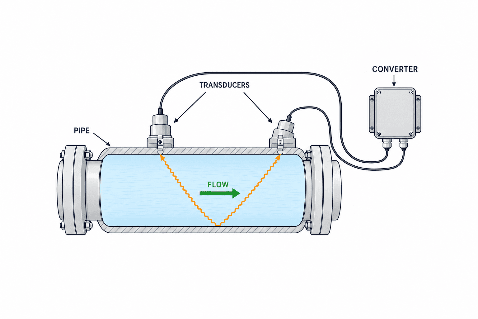
A common transit-time meter sends ultrasound through the liquid between transducers on the outside of the pipe. The difference between travel times with and against the flow is used to derive velocity. The sensor can be installed without a wetted opening and, in suitable locations, without interrupting the process. A temporary unit can also be moved between proposed locations before buying the permanent system. KROHNE describes its OPTISONIC 6300 as a permanent clamp-on device for installations where cutting the pipe or stopping the process is undesirable. KROHNE product information
The acoustic path passes through the pipe wall and possibly a lining as well as the liquid. Incorrect wall or lining thickness, material, or sound-speed inputs can lead to incorrect transducer spacing and flow conversion. Verify actual outside diameter, wall thickness, lining, corrosion, and scale rather than relying on nominal pipe size. Entrained gas or solids may impair a given model’s signal; confirm the selected technology against the worst operating medium. Older steel, cement-lined, and composite pipes deserve a field trial rather than a paper-only approval.
Non-intrusive does not mean no installation work
Insulation may need to be opened and restored. The surface may need cleaning, paint or rust treatment, permanent mounting hardware, cable support, power, communications wiring, and weather protection. Access platforms and hot-work or electrical permits may also be needed. A Flexim operating manual describes preparing the pipe surface, removing loose rust or paint, applying a coupling medium, and avoiding air pockets between the transducer and pipe wall. Emerson/Flexim manual
Build a pipe card before comparing factory flow meters
Create one site card for each measurement point: line and tag, liquid, actual outside diameter, nominal size, material, wall thickness, lining and insulation, design and operating temperature, typical/minimum/maximum flow, orientation, photographs, nearby elbows/valves/branches, available power, and distance to the PLC. Keep separate columns for drawing values and field-verified values. A historical piping drawing may not reflect later repairs or replacement.
| Item | Verify on site | Risk if unknown |
|---|---|---|
| Pipe dimensions | Actual OD, wall data, lining thickness | Incorrect bore and sensor spacing |
| Medium | Liquid, temperature, bubbles, solids, viscosity changes | Uncertain signal and model suitability |
| Flow | Minimum, normal, maximum, stop, reverse | Incorrect range, scaling, totalization |
| Inside condition | Full pipe, trapped air, deposits, corrosion | Unstable or absent signal |
| Environment | Flooding, heat, vibration, access | Wrong enclosure or service plan |
| Integration | PLC input, power, protocol, tag | Value visible locally but unusable in operations |
The card makes vendor replies comparable. If one bidder assumes clean water in bare carbon steel while another assumes a hot lined pipe, their prices do not describe the same solution. Mark unknown values “field test required” or “contractor to measure”; ask each bidder to price that work explicitly.
Check liquid, bubbles, and the full-pipe condition
Transit-time measurement requires an adequate acoustic signal and a suitable flow profile. Air at the top of a horizontal pipe may block the sound path. Pay special attention to pump suction, descending pipes, intermittent lines, and discharge to open tanks. Assess filling and gas not just at normal output but at start, stop, and minimum flow. Siemens identifies a completely full sensor installation volume as a requirement for accurate FS220 measurement. Siemens product information
Moving the sensor location may improve a difficult signal, but a stable number on the display is not proof that the data are fit for a decision. Record diagnostics, signal quality, error events, and an independent comparison. If liquid properties change by production batch, include the least favorable batch in the trial. If no location produces a usable result, evaluate another measurement method instead of forcing the original selection.
Inspect wall, lining, insulation, and the mounting surface
Record lining material and thickness, possible delamination, and deposits that may change over time. A clean signal on day one cannot guarantee one-year performance when buildup grows. External paint, unevenness, welds, and corrosion affect acoustic coupling. For a hot line, evaluate the sensor temperature rating together with insulation restoration, cable routing, and safe maintenance access. Endress+Hauser’s instructions for a high-temperature clamp-on application describe preparing a clean, smooth, even coupling surface. Endress+Hauser pipe preparation document
How much straight run does an ultrasonic flow meter need?
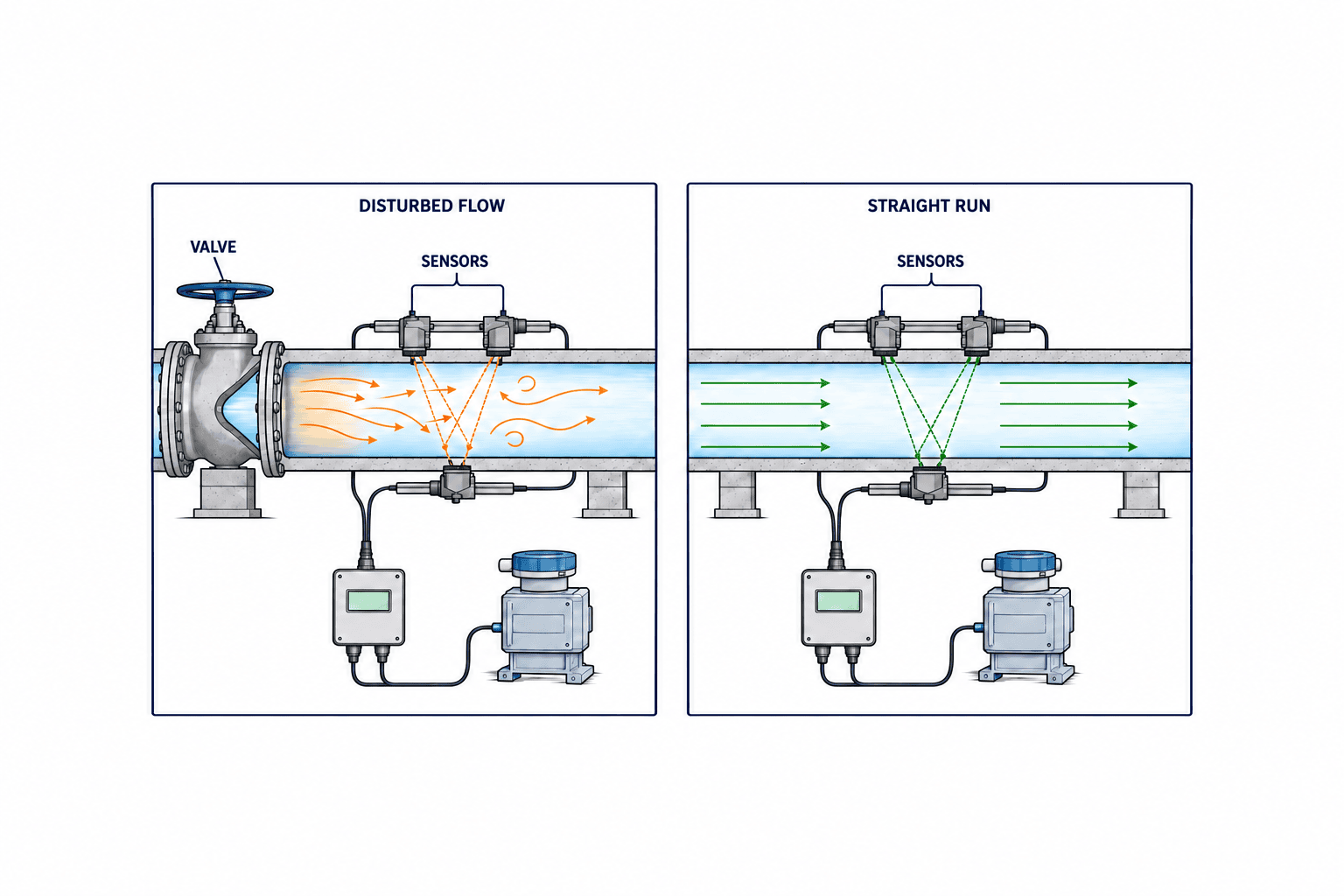
There is no universal “10D upstream and 5D downstream” rule for every instrument and disturbance. The answer changes with the product, mounting arrangement, elbows, partially open valves, pipe diameter, and required error limit. Siemens lists a typical minimum of 10 diameters upstream and 5 downstream for its FS220, with more run for double out-of-plane elbows and partially open valves. This is a condition stated for that product, not a guarantee for all clamp-on meters. Siemens technical specification
Emerson describes a flow-disturbance correction function for the Flexim FLUXUS F731 WD. That feature should still be checked in the actual pipe geometry against the project’s acceptance criterion. Neither a brochure value nor a correction feature replaces a site trial. Emerson product information
Drawing distance is not the entire flow profile
Record bends, throttled valves, pumps, reducers, tees, and check valves upstream. The mounting rail also needs physical clearance and a way to replace or inspect the transducers. Photograph the flow direction and valve positions; convert distances to pipe diameters on the site sketch. Where straight run is limited, compare candidate locations and signal quality, ask the vendor to explain any applicable correction, and define the acceptance test. If the required performance cannot be demonstrated, seek a pipe modification or alternative technology quotation.
Compare models on total delivered performance
A portable trial before choosing a fixed meter can prevent expensive rework. Log normal and low flow, pump changeover, start-up, and shutdown where safe. Compare not just instrument prices but site survey, trial, brackets, cabling, panel work, PLC changes, HMI graphics, training, spares, and maintenance. Avoiding a pipe cut does not make instrumentation or data integration free.
| Comparison | Evidence requested | Decision check |
|---|---|---|
| Medium and pipe fit | Selection sheet using measured site data | Suitable, trial needed, or unsuitable |
| Minimum flow | Low-flow trial and diagnostic log | Stable enough for alarm or totalization |
| High and reverse flow | Range and output scaling | PLC sign, limit, and totalizer match |
| Mounting | Full pipe, straight run, bubbles, vibration | Can the rule be placed on the site drawing? |
| Diagnostics | Signal-quality and fault outputs | Can maintenance isolate a problem? |
| Connectivity | Exact model’s 4–20 mA / Modbus details | Fits the existing panel and system |
| Lifetime cost | Coupling, remounting, spares | Compare first-year and continuing cost |
Ask whether a stated accuracy is based on reading or full scale, and what liquid, pipe, velocity, and installation conditions were used. The same percentage can imply very different uncertainty at minimum flow. Process monitoring may prioritize repeatability and anomaly detection. Custody transfer or regulated metrology can require separate certification and calibration; this buying guide does not establish suitability for those uses.
Document a conditional selection: “Use model A if the specified line stays full, it reaches the agreed signal quality at minimum flow, and the PLC receives correct values.” Maintenance, utilities, production engineering, controls, and IT often hold different pieces of the required information. A short cross-functional review before the purchase order prevents a pipe-compatible meter from becoming an unusable data source.
Plan a retrofit from portable trial to permanent installation
At each trial location, measure the pipe, prepare the surface, and enter the liquid, pipe, lining, and temperature data requested by the instrument. Save signal strength, diagnostic indicators, transit times if available, and stable and transient readings. Compare trends with pump current, pressure, or tank-level movement to identify obvious contradictions. Such process indicators do not replace a calibrated reference when an accuracy claim must be proven.
Compare candidate locations on one sheet: acoustic quality, straight run, access, cable length, maintenance risk, and future plant changes. Photograph transducer orientation and spacing, couplant, brackets, and software settings. Reinstallation can alter coupling and geometry, so repeat the acceptance checks after permanent mounting rather than assuming the portable result transfers unchanged.
Match the trial to the application
For cooling-water circulation, include low and high seasonal loads and pump changeover. If future heat calculations are planned, design compatible inlet and outlet temperature measurement and timestamping now; a flow history alone cannot reconstruct missing temperatures. For utility water, separate night-flow leak detection from monthly cost allocation. The former needs low-flow stability and a baseline, while the latter needs reliable totalizers and clear rules for power outages and missing data.
For wastewater and chemical circulation, record bubbles, suspended material, liquid changes, and internal fouling. Do not label every process liquid simply “water.” Test the least favorable operating state and, where deposits accumulate, choose a trial duration that covers the relevant operating cycle. A batch line that changes liquids also needs controlled settings and operator instructions.
Define a stop rule when a trial fails
When readings are absent, check pipe dimensions and material input, transducer direction, couplant, surface, filling, and gas, changing one variable at a time and recording diagnostics before and after. Agree beforehand how many locations to try, what signal threshold is acceptable, and when to pursue another technology. A failed trial with good pipe and diagnostic records still improves the next selection. If the meter is stable but the PLC value jumps, investigate wiring and scaling; if only low-tank-level periods lose signal, investigate filling.
Design PLC and network integration in parallel
For 4–20 mA, specify zero/span, fault current, isolation, shielding, grounding, and cable route. For Modbus, identify RTU or TCP, register map, data type, word order, polling rate, and behavior on a broken link. “Modbus ready” is not enough detail. Test matching units, signs, and digits between the local display, PLC tag, and historian in SAT.
Pairing water flow with other measurements can make it more useful. Our guide to cooling-tower water quality monitoring discusses data collection around a cooling system. For wastewater lines, the industrial wastewater dissolved-oxygen sensor selection guide shows why sensor maintenance and data trust belong in the operating plan.
Put site conditions and acceptance criteria in the RFP
Attach pipe cards, liquid and temperature ranges, flow range, photos and layout, straight-run limits, full-pipe information, required outputs, power, environmental conditions, trial scope, documentation, warranty, and service scope. Mark drawing values that require field verification. Ask bidders for transmitter and sensor model numbers, selection assumptions, excluded conditions, trial plan, installation scope, diagnostic acceptance rule, comparison method, total price, and delivery schedule. Include a “included / excluded” column for cables, clamps, weather boxes, configuration software, trial labor, and PLC/HMI modifications.
Ask pointed questions: Which inputs must be measured before order? How are minimum and maximum flow addressed? What happens if straight run is short? How is an uncertain lining or deposit handled? How does the PLC identify a meter fault? When will the Modbus map be supplied? How are settings backed up? What are the Thai service and spare-parts arrangements? Record each conditional answer in the purchase specification. If a trial might fail, agree the fallback design, cost responsibility, and schedule before issuing the purchase order.
Sample RFP wording
Measure an existing cooling-water line continuously using an external meter without interrupting normal production. Pipe details are in the attached site card. Before order, test normal flow, low flow, and pump changeover; log acoustic diagnostics, local reading, and PLC reading. State requirements for full pipe, straight run, gas, pipe wall, and lining. Explain the choice of 4–20 mA or Modbus and behavior on measurement or communications failure. After permanent installation, perform SAT against the agreed site-trial and integration criteria and hand the settings and maintenance procedure to plant staff.
Adapt the example to the actual process. A reversing wastewater line needs bidirectional totalization. A hot pipe needs sensor temperature limits and insulation reinstatement. A flooded pit needs protection for connection points and transmitter as well as the transducers.
Separate FAT from SAT
FAT verifies the ordered hardware and the configuration that can be checked before shipment: power, I/O, display, communications, alarm, tag number, and documents. A factory bench normally cannot prove accuracy on the final plant pipe. Mark items that require site conditions for SAT. For analog output, test several points against PLC scaling. For communications, test key registers and diagnostic codes.
SAT tests the installed system under the actual pipe and operating conditions: measured dimensions and programmed values, transducer orientation and spacing, coupling, full-pipe status, acoustic diagnostics, instantaneous and totalized flow, reverse flow if relevant, power recovery, communications failure, alarms, and HMI display. Include low flow and changeover where practical. Define numeric pass criteria in the RFP for the selected duty and model; do not copy an unconditional catalog percentage. Where comparison with a reference is needed, agree the method, uncertainty, time, and operating state.
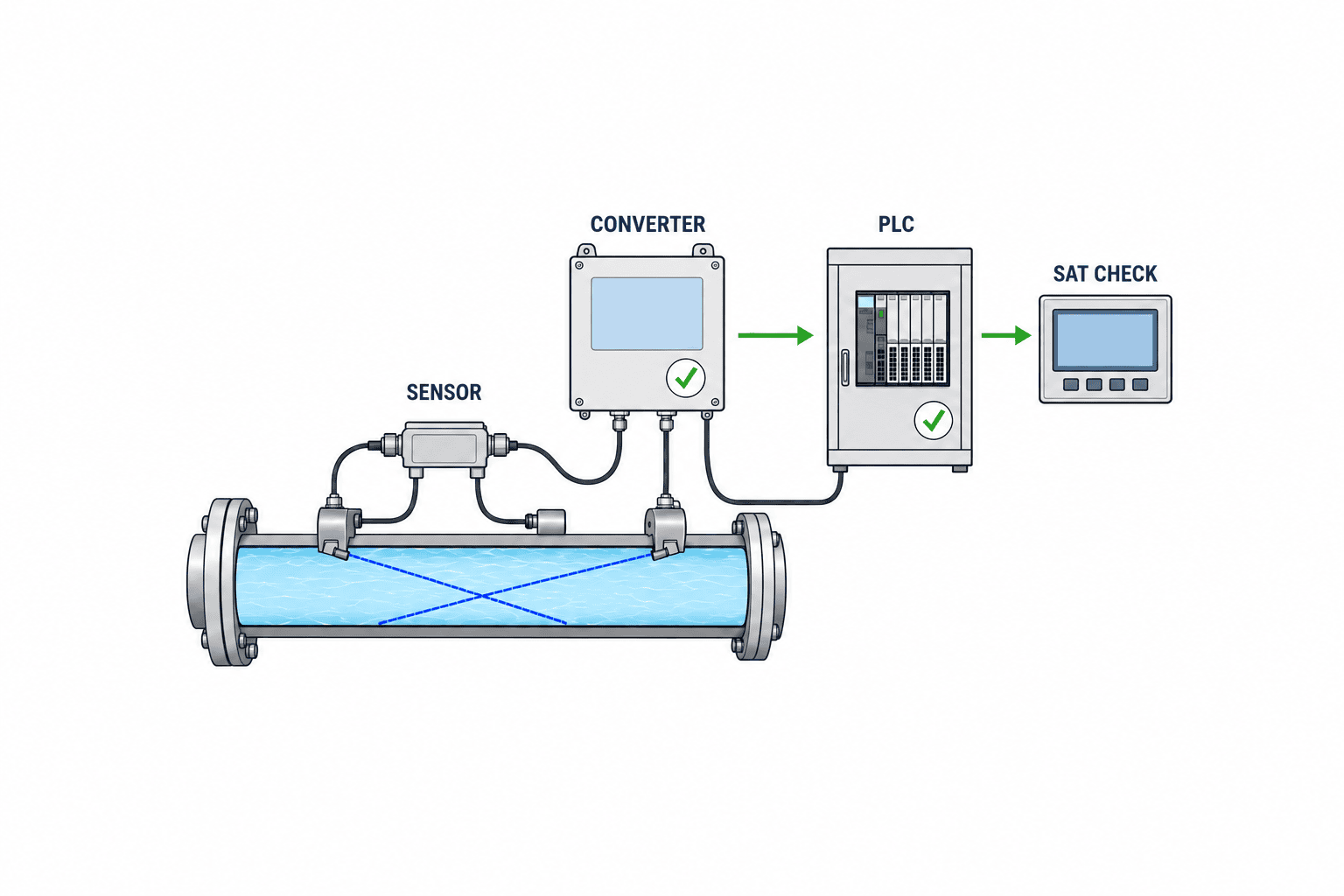
Keep the final pipe card, configuration backup, mounting photographs, wiring diagram, tag list, register map, trial logs, troubleshooting contacts, and coupling replacement instructions. Insulation can hide the installed location, so mark it outside and allow safe reopening. After remounting a sensor, replacing a pipe, or changing the fluid, recheck inputs and acoustic signal.
Common mistakes and what to do instead
Ordering from nominal pipe size alone can lead to wrong bore and sensor spacing; verify actual dimensions. Choosing the easiest mounting point may place the sensor directly after a valve or near trapped gas; assess the flow profile. Treating the first displayed number as acceptance can hide dropouts on pump changeover, unstable low flow, PLC scaling errors, and totalizer resets; test operating scenarios at both instrument and system level. Burying a transducer under insulation without access makes routine recoupling difficult; design a serviceable location.
A model-specific performance claim is not a plant-specific guarantee. Link any performance commitment to the transmitter and sensor, liquid, pipe, installation point, velocity, and comparison method. Use a portable trial to reduce uncertainty before committing the full project budget.
Turn flow data into maintenance and improvement
Store timestamped data with pump state, valve position, pressure, temperature, and production load. A falling circulation rate could indicate a blocked strainer, pump wear, valve change, or leak; flow alone does not identify the cause. Define who checks the trend and which corroborating signals or inspections follow an alarm. Tune thresholds after observing normal operating distributions by shift and load; a single threshold across start-up and steady operation often causes false alarms. Show instrument diagnostics and communications status alongside the process value so staff can distinguish a process change from a meter fault.
Monitor mounting hardware, cables, water ingress, configuration history, and acoustic quality. Long-life coupling products still need a site-specific inspection schedule for heat, vibration, washdown, or outdoor exposure. KROHNE describes re-greasing and solid coupling-pad options; Emerson describes permanent coupling for a water application. Obtain the maintenance procedure for the exact selected model and register it in the plant asset system. KROHNE product information / Emerson product information
FAQ: clamp-on ultrasonic flow meter selection
Can an existing pipe always be instrumented without stopping production?
An external sensor avoids cutting the line in a suitable application. Safe access, insulation work, electrical work, permits, and hot or elevated surfaces may still affect the work plan. Confirm the production and safety arrangements for the actual location.
What if the ultrasonic meter has insufficient straight run?
Try another point, review model-specific correction and limitations, and conduct a site comparison against the required performance. If this cannot demonstrate an acceptable result, quote pipe changes or a different measurement method. There is no universal D value applicable to every product and disturbance.
What accuracy percentage should we assume?
No single number is valid for all models and installations. Ask whether the claim is based on reading or full scale and document pipe size, velocity, liquid, straight run, mounting, and calibration method. Monitoring and regulated metrology also have different acceptance needs.
Should we use 4–20 mA or Modbus?
Choose against the available PLC input and required data. An analog signal can be simple for instantaneous flow; digital communications may better expose totals and diagnostics. Specify fault behavior and verify the local and remote values in SAT.
Do we need both FAT and SAT?
They answer different questions. FAT checks supplied hardware, I/O, configuration, and documents before shipment. SAT checks mounting, signal, operation, and integration on the actual pipe. A small project may simplify FAT, but site-dependent checks must remain in SAT.
Conclusion: verify the pipe and purpose before the meter
The value of a clamp-on ultrasonic flow meter is its potential to add data without opening the process. Assess the liquid, wall, lining, full-pipe state, straight run, and minimum flow before comparing bids. Use a portable trial to test uncertainty, put assumptions and pass criteria in the RFP, and use FAT and SAT to verify both instrument and PLC integration.
If your Thai plant is still identifying measurement points or writing the RFP and SAT plan, contact TOMAS TECH. We can help structure the pipe data, trial questions, and path from measured flow to useful operations data.


