


Selecting a control cabinet cooling fan for a factory in Thailand takes more than comparing the maximum airflow printed on product pages. The decision joins the equipment heat loss, the hottest credible air at the intake, the allowable temperature around sensitive components, the pressure drop across filters and outlets, and the exposure to dust or water. This guide gives purchasing and engineering teams a route from the cooling-method decision to a preliminary airflow calculation, a comparable RFP, and evidence at FAT and SAT. Confirm the standards and final product rating against the actual assembly, destination market and component manufacturers’ instructions.
First decide whether outside air may enter the cabinet
A filter fan draws ambient air into the enclosure and exhausts air carrying the internal heat. It therefore needs ambient air that is sufficiently cooler than the target internal air and sufficiently clean for direct intake. Rittal describes those two conditions for cooling with ambient air. Increasing fan airflow cannot cool the cabinet below the incoming air temperature. If oil mist, washdown, corrosive vapour or heavy dust makes direct ventilation unsuitable, consider a separated air circuit before selecting a bigger fan. Rittal’s overview of fans and heat exchangers explains the operating distinction.
| Site condition | Candidate method | Main question |
|---|---|---|
| Ambient air is cooler than the required cabinet temperature and acceptably clean | Filter fan with a suitable outlet filter | What is the operating airflow after all restrictions? |
| Ambient air is cooler, but must not enter the enclosure | Air-to-air heat exchanger | Is the temperature difference sufficient for the required heat removal? |
| Ambient air is at or above the target temperature | Cabinet cooling unit or suitable chilled-water solution | What capacity, drainage, exhaust and utilities are needed? |
| Water, oil, chemical or severe dust exposure is present | Reconsider a sealed cooling design | What protection does the completed assembly require? |
An air-to-air exchanger keeps its internal and external air circuits separate and relies on a temperature difference. An air-to-water exchanger with an appropriate chilled-water source, or an active cabinet air conditioner, can be evaluated where the interior must be below ambient. These are engineering options, not interchangeable catalogue labels. Rittal’s technical climate-control guide sets out their different applications.
Build the thermal input sheet before asking for a fan quote
List the losses in watts for drives, servo amplifiers, power supplies, transformers, braking resistors, communications equipment and other devices inside the cabinet. Use component loss data for each operating mode rather than treating the entire connected electrical load as cabinet heat. Record which machines operate simultaneously and whether external resistors or heat sinks move some loss outside the cabinet. Keep the present installation and planned future expansion as separate cases. A bigger cooling unit cannot correct a blocked airflow path or a heat-sensitive device mounted against a concentrated source.
Set ambient temperature at the intended intake, not at a distant room thermostat. A cabinet near an oven, loading door or roof can see conditions unlike those in an air-conditioned office. Adjacent cabinets may recirculate each other’s warm exhaust. If production must continue when room air conditioning stops, include that state. For the interior limit, consult the lowest applicable component ambient rating and its derating instructions, installation clearances and required air direction. An average thermometer at the cabinet door does not establish the conditions at a drive intake.
The enclosure surface, material, wall proximity, solar exposure and adjacent equipment affect passive heat transfer. IEC TR 60890:2022 covers a method for calculating air temperature rise in enclosures for low-voltage switchgear and controlgear assemblies or similar products; the IEC describes it as primarily applicable to enclosed assemblies without forced ventilation. Do not present a calculation under that report as proof of a particular fan’s installed airflow without checking its scope and the product data. IEC TR 60890:2022
| RFP input | What to record | Evidence |
|---|---|---|
| Heat loss | Watts per device, duty state, simultaneous operation, planned additions | Component data sheets and load list |
| Ambient environment | Normal and maximum intake temperature, dust, water, oil, chemicals, solar load | Site measurements, layout, photographs |
| Internal limit | Allowed temperature and derating for each limiting component | Installation instructions |
| Assembly | Size, material, openings, wall clearance and fan locations | Approved layout and survey |
| Protection | Required protection of the completed assembly and washdown conditions | Customer specification and maintenance plan |
| Acceptance | Loads, ambient conditions, measurement points and pass criteria for FAT and SAT | Approved test procedure |
Our control panel design guide for Thailand covers the wider circuit, thermal and FAT design baseline. Here we focus on the cooling unit and the physical air path.
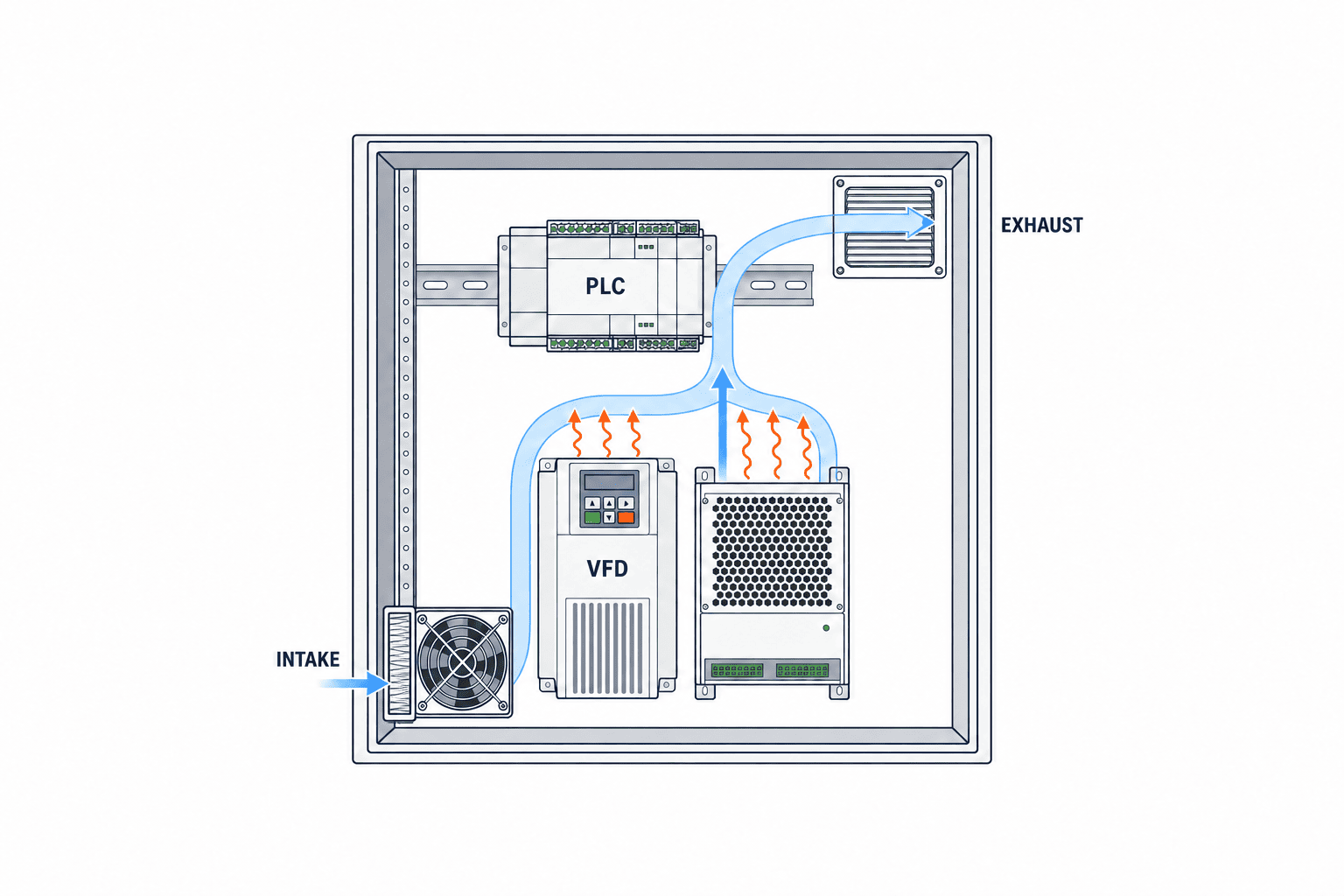
Cabinet cooling fan airflow calculation: a starting point, not a part number
The sensible-heat relation is heat Q in watts = mass airflow in kg/s × air specific heat cp in J/(kg·K) × temperature difference ΔT in K. Written with volumetric airflow V in m³/h, a preliminary estimate is V = 3600Q/(ρcpΔT), where ρ is air density in kg/m³. Rittal gives this relation for filter-fan sizing and notes that density and specific heat vary with temperature and pressure. Rittal filter-fan white paper
For an illustrative calculation only, suppose the heat to be carried by air is 500 W, the permitted inlet-to-outlet difference is 10 K, density is 1.2 kg/m³ and cp is 1005 J/(kg·K). The equation gives about 149 m³/h. That number is neither a model recommendation nor guaranteed airflow in a factory. The real design must account for heat exchanged through enclosure walls, heat coming from outside, component hot spots, inlet and outlet placement, and the pressure drop of actual filters and grilles. Schneider Electric warns that manual calculations have uncertainty when enclosure-wall heat transfer is not known and recommends dedicated thermal calculation where precision matters. Schneider Electric airflow FAQ
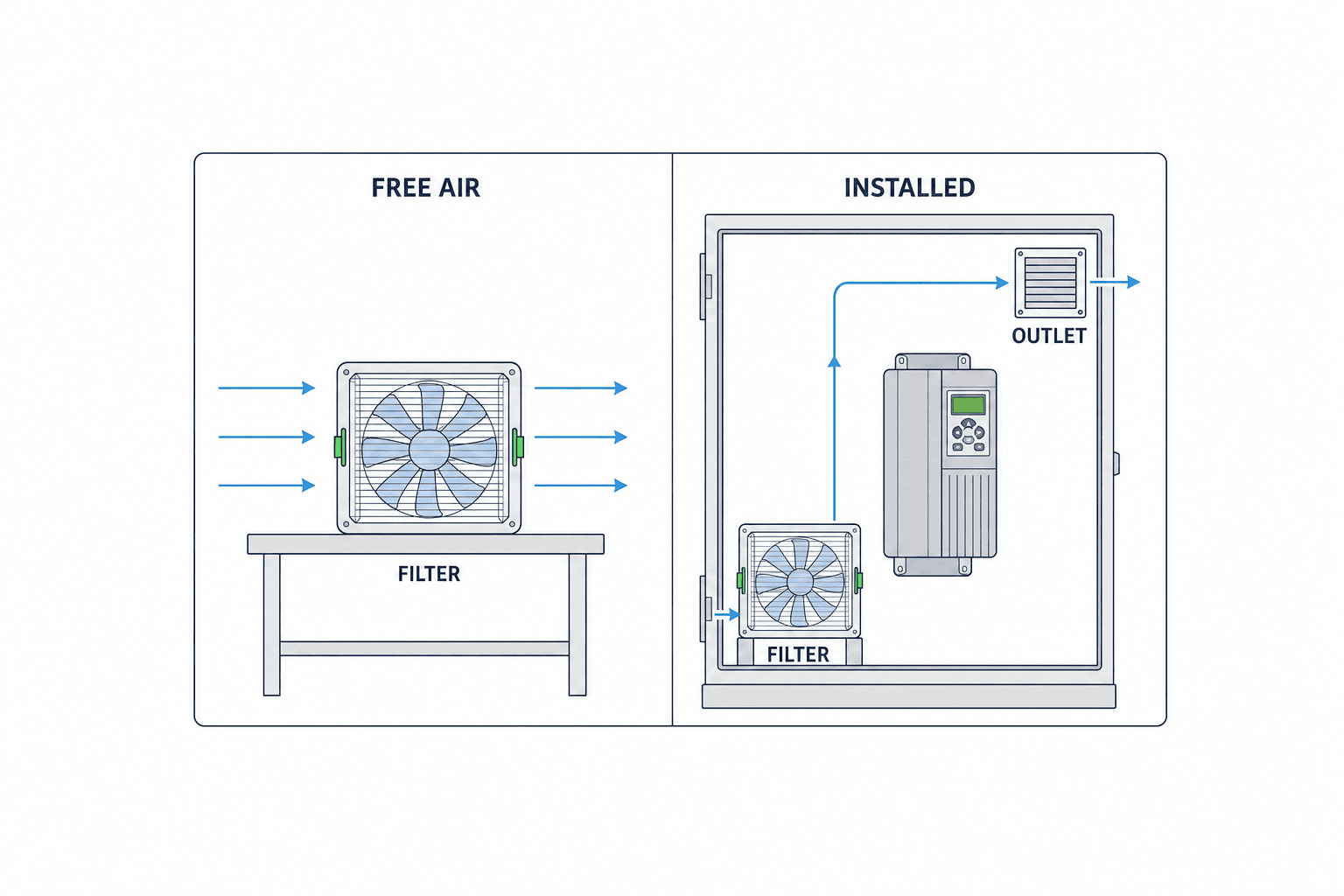
Compare the required airflow with the fan’s operating point in the installed system, not its unrestricted free-air maximum. The intake filter, outlet filter, grille and any duct produce resistance. A dirty filter changes that resistance further. A narrow outlet or dense cable duct can reduce useful flow, and a nearby intake and exhaust can create a short circuit that bypasses the hot components. Schneider Electric’s ClimaSys brochure explicitly calls out outlet-element pressure loss and regular filter cleaning and replacement. ClimaSys enclosure thermal management brochure
Avoid an unexplained blanket percentage for design margin. State the uncertainty in heat-loss inputs, peak ambient, filter loading, added devices, performance tolerances and power supply. Then identify the operating point on the manufacturer’s fan curve. With more than one fan, review each route through the cabinet and its outlet resistance rather than summing free-air ratings. A component that needs a particular airflow direction or clearance still needs that local condition, even if the total cabinet airflow is ample.
Five checks when choosing a control cabinet filter fan
1. Route the air across the real heat sources
Draw the intake, exhaust, obstacles, hot devices and measurement points on the cabinet layout. Spacing intake and exhaust apart helps prevent recirculation, but do not blindly impose a bottom-in, top-out arrangement. Check drive instructions, cable ducts, door-mounted devices, neighbouring cabinets and where dust settles. Air that travels straight from intake to exhaust can produce an acceptable total flow reading while leaving a drive hot.
2. Include the dirty-filter state
Filter media reduce particle ingress but add resistance, especially as they load. Select the media and inspection frequency for the site, with room for a technician to remove and refit them safely. Severe contamination may justify a closed-circuit exchanger or active cooling instead of ever more frequent replacements. Compare consumables, labour and production interruption, not only the fan price. Rittal notes situations where filter fans are unsuitable, including heavily dusty or oil-contaminated air. Rittal enclosure selection guide
3. Check the protection of the completed cabinet
IEC 60529 classifies degrees of protection provided by enclosures, expressed as IP codes. An IP statement for a fan’s front piece does not automatically establish the rating of the completed cabinet with doors, cable glands, exhaust openings, new holes and gaskets. Specify the required assembled condition, mounting orientation, filter media, washdown exposure and how maintenance preserves it. An IP code alone does not settle corrosion, condensation, oil mist, UV or thermal performance. IEC 60529
4. Define controls and failure behaviour
Specify supply voltage and frequency, fan control, rotation or failure detection, cabinet temperature alarms and any filter-loading indication. A thermostat may reduce unnecessary runtime, but its set points must account for heat at startup and the site’s humidity conditions. Decide whether a fan failure stops the line, creates an alarm, or triggers a controlled reduction in load. Put the chosen signals in the schematic, I/O list and alarm register; do not assume an optional catalogue function is installed.
5. Make maintenance physically possible
Confirm replacement parts and availability in Thailand, filter compatibility, access direction and the safe isolation procedure. A layout that requires moving the cabinet to reach a filter or unnecessary exposure to live components is a poor maintenance design. Agree on inspection evidence suitable to the site, such as measured temperature trends, visible loading or available differential-pressure indication. Record baseline readings at handover so a future rise can be investigated.
When to choose a heat exchanger or cabinet air conditioner
Teams often say simply that they need to “cool the panel,” while meaning different outcomes. The first question is whether a temperature above ambient is acceptable inside the cabinet, or whether the cabinet must stay below ambient. Filter fans are a practical candidate when outside air is cool enough and clean enough. If air ingress is unacceptable but the outside remains cooler, an air-to-air exchanger provides separated circuits, subject to adequate temperature difference and capacity. If the desired internal temperature is below ambient, evaluate an active cooling unit or a properly supported chilled-water solution. Rittal method comparison
A Thai plant may have a conditioned assembly room, a hot roof-level area and a washdown zone on the same site. Measure conditions at each intake rather than applying one “factory ambient” to every panel. With an air conditioner, check the destination of the rejected heat, drainage or condensate management, power, service access and alarms. Even a sealed design depends on doors being closed and seals maintained. Temperature control and condensation control are separate decisions: check humidity, door openings and temperature changes at shutdown. Evaluate energy, filters, cleaning, downtime, spares and recovery alongside capital cost.
Write the cooling requirement into the RFP
A purchasing example: identical cabinets can need different cooling methods
Imagine two cabinets containing the same VFD and PLC. One sits in an air-conditioned assembly room; the other stands beside a conveyor under a hot roof. The equipment losses are identical, but the air temperature at each intake changes the allowable ΔT. The assembly-room cabinet may be able to admit ambient air. Dust and warm exhaust near the conveyor may make copying the same filter-fan design inappropriate. Determine the maximum intake temperature, contamination, component limits and operation during building-air-conditioning outages for each location before choosing a model.
Now suppose the as-built cable duct becomes wider than the approved layout and partly blocks the upper outlet. Even if the original calculation showed enough flow, the installed operating point and local temperatures have changed. Require a drawing of the actual route, selected filters, maintenance clearance and FAT visual inspection as well as the calculation. At SAT, record outside and inside temperatures at the same load. The calculation, drawing, assembled cabinet and measurement must agree for the choice to be reproducible.
Bidder A might propose a fan subject to frequent filter cleaning, bidder B a sealed heat exchanger, and bidder C a cabinet air conditioner. Do not rank only the purchase price. Compare ability to meet the temperature and ingress requirements alongside consumables, electricity, maintenance labour and downtime. If one method must be specified in advance, request the conditions under which it ceases to apply and an alternative. That question can expose a missing site assumption.
Keep the calculation auditable in the design file
State whether Q in the airflow equation means all internal device losses or the remaining heat to be carried by air after accounting for passive transfer through the enclosure. Mixing those definitions produces different answers from the same formula. If passive transfer is credited, document effective surface area, material, wall clearance, environmental inputs and the method or software version used. Do not assign zero loss to a device with missing data; record the source to be obtained and any temporary assumption. For future expansion, decide whether the initial fan includes capacity or whether replacement is planned at the upgrade.
ΔT is an assumed difference between inlet and outlet air for the design case, not a convenient instantaneous difference between any two thermometers. It must be checked separately against the temperature allowed at each sensitive component. A larger permitted ΔT reduces the calculated flow but may leave a component intake too hot. An unnecessarily small ΔT can drive a larger fan, increasing openings, energy, noise and filter loading. Return from the equation to product curves, layout and component limits before final selection.
Evidence for installed airflow needs the manufacturer’s pressure-flow curve and the resistance of the selected intake and outlet parts. Changing filter media, adding an outlet louvre or adding a protective cover can move the operating point. A spinning fan alone does not prove useful airflow across the heat sources. Check both the route on the drawing and measured local temperatures. Keep drawing and calculation revisions aligned with the actual parts at FAT; a same-size substitute may differ in fan curve, filter, power, noise, ingress protection or spares. Archive the installed model, drawings, filter part number, settings and SAT record together for the next modification.
“Provide a cooling fan” is not a comparable purchasing specification. The purchaser should freeze the operating assumptions, and each bidder should submit its heat balance, selected method, airflow at the installed operating point, arrangement drawing and test plan. If an input has not been measured, identify it as an estimate, give a measurement date and define the change process. Add the following cooling fields to the wider scope described in our control panel manufacturing and handover guide.
| RFP field | Response requested from the supplier |
|---|---|
| Thermal balance | Device losses, duty cases, ambient and internal limits, treatment of passive transfer |
| Method | Why fan, exchanger or active cooler fits; conditions under which it does not |
| Airflow | Equation, assumptions, required flow and operating flow on product curves |
| Physical route | Intake, outlet, filters, obstacles, heat sources and measurement locations |
| Exposure and IP | Completed-cabinet target, openings, mounting and cleaning conditions |
| Electrical and service | Supply, control, alarms, fault response, filter replacement and spares |
| Acceptance | What FAT will prove, what SAT will measure, and correction if criteria are missed |
Check first that every bid uses the same ambient maximum, loss case and internal limit. A free-air rating from one supplier is not comparable to another’s filter-equipped operating flow. Specify the load, ambient condition, points and duration or recording method used to judge the temperature limit. Otherwise a warranty stating “cabinet temperature acceptable” has no reproducible test behind it.
FAT at the panel builder
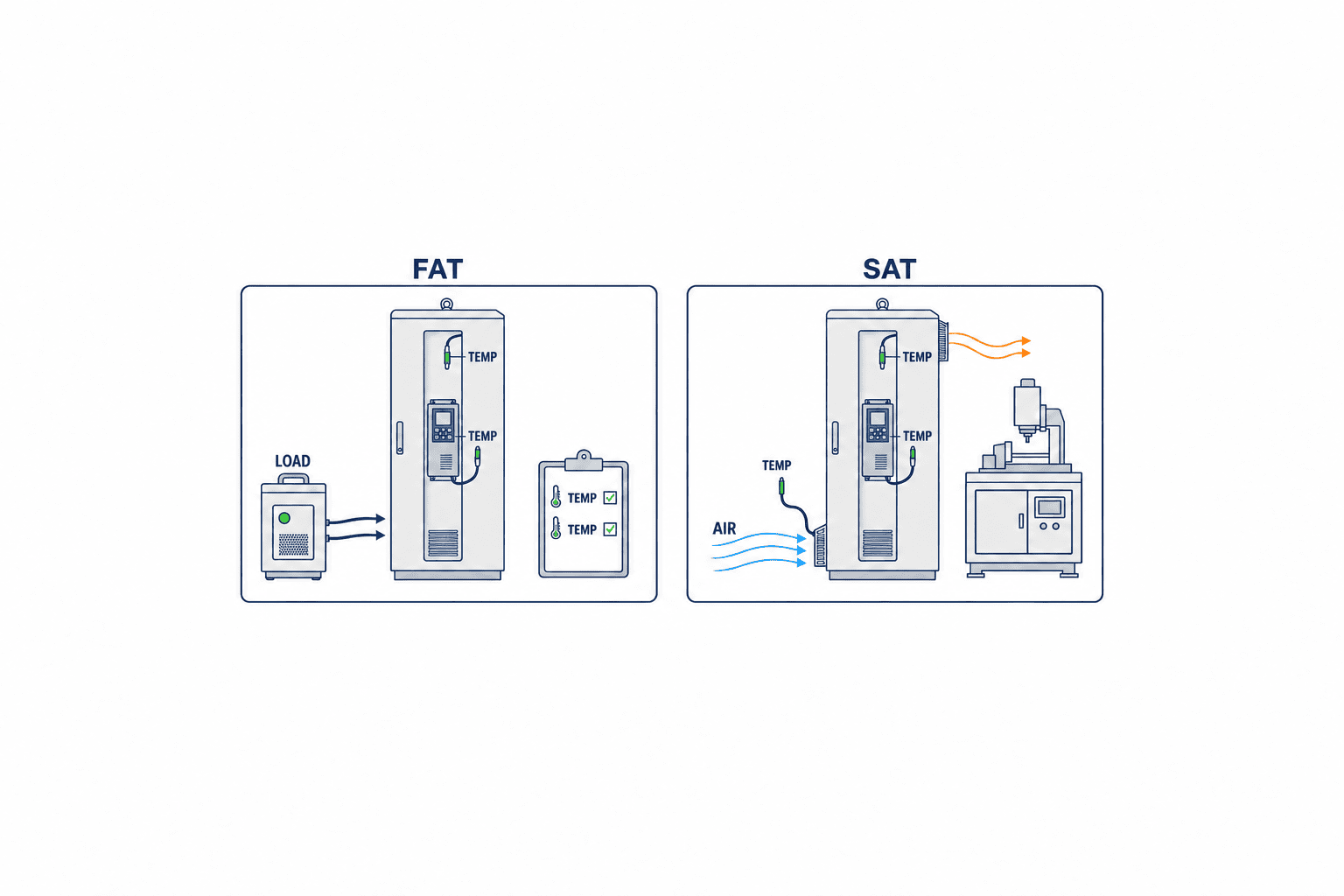
Inspect the actual fan model and orientation, openings, filter materials, power, alarms and service access against the approved drawings. Confirm that cable ducts and door devices do not obstruct the intended route when the door is closed. Record available temperature tests with their workshop ambient and applied load. If factory conditions cannot reproduce the site’s hottest state, list the gap explicitly for SAT. Exercise only the fan-stop, overtemperature or loading alarms that are actually included in the design.
SAT in the Thai factory
At the installed location, measure the real operating load and intake ambient at the same time as internal points. Include the intake of the most temperature-limited device, upper cabinet region and exhaust as agreed. Close the door and record adjacent exhaust and room-air-conditioning state. If the peak seasonal or production load was unavailable, schedule the outstanding verification and identify its owner instead of calling it proven. On a failed temperature criterion, investigate heat load, flow short circuit, blocked filter, fan operating point and surrounding exhaust before simply replacing the fan.
Common mistakes and when to reconsider the selection
The first mistake is trying to cure high ambient temperature by simply increasing fan size. Ventilation cannot make cabinet air cooler than its incoming air. The second is comparing a fan’s unrestricted maximum rating directly with calculated demand, rather than its filtered operating point. The third is treating a fan-front IP declaration as the protection of the completed cabinet, including door, cable entries, site machining and maintenance condition.
A fourth mistake is measuring only the centre of the cabinet door. Hot spots may remain at a VFD intake, at the top of the cabinet or behind tightly packed equipment. A fifth is leaving filter replacement outside the design and handover documents. A sixth is failing to reassess the heat balance after another component is installed: even a small change can alter losses, airflow, available power or cabinet openings. Update the loss sheet and acceptance case through change control.
Do not interpret every single alarm as proof that a different model is needed. Record load, ambient temperature, door position and filter state at the alarm, then identify which design assumption changed. For a stopped fan check supply and controls; for low flow inspect media and outlet resistance; for a local hot spot review routing and device position. If a harsher environmental condition has become permanent, reassess the cooling method and the protection of the finished assembly, not just fan capacity. Operating with the door open is not a permanent acceptance state.
For a site investigation, log the product, operating mode and nearby equipment at the same times as temperatures before and after the alarm. A fall in temperature after filter cleaning suggests the filter contributed, but different loads or ambient temperatures before and after cleaning prevent a simple causal conclusion. The fan may visibly rotate while packaging material near the intake or an object against the exhaust still restricts the useful flow. Once the cause is established, measure again under comparable load and ambient conditions after corrective work, then update drawings, maintenance instructions and alarm settings. This record becomes reusable design evidence for the next expansion or another cabinet of the same type.
Retrofit cooling: survey before cutting the enclosure
For an existing panel, collect load history, alarms, cabinet temperatures and nearby ambient at the same times. A trip at one production stage may reflect simultaneous losses or a neighbouring machine’s exhaust. The fact that an open door lowers temperature suggests a thermal issue but does not prove a fan is appropriate; it also admits dust and moisture. Check busbars, protective bonding, wiring, door devices, mechanical strength and safe access before cutting a new opening. Plan control of metal swarf and inspection after machining. An intake without sufficient outlet area will not deliver the intended flow. Verify supply and protection for the new fan and ensure its wiring does not obstruct the route.
Older gaskets and cable glands may already have weakened ingress protection. Review the modified assembly against its current installation environment and document the completed state. If the enclosure lacks space, compare moving a heat source outside, changing enclosure construction, or replacing the panel. A retrofit is an assembly change, not a one-line accessory purchase.
Keep the accepted condition in service
At handover, retain baseline internal and ambient temperatures, sensor locations, loading state, alarms, filter cleaning or replacement criteria, and the post-maintenance check. A later temperature rise can then be traced to a hotter environment, changed load, stopped fan, clogged media or wiring added across the flow path. Changes to components should update the loss list and review whether measurements or acceptance conditions need repeating. A temperature trend is only comparable when measurement location, calibration, load and ambient are understood.
FAQ: control cabinet cooling fan selection
Is the calculated airflow enough to choose a model?
No. It is a starting requirement. Confirm installed airflow with filters and outlets, the physical route, local component temperatures, ambient exposure and the agreed FAT/SAT evidence.
Can a filter fan be used on a high-IP cabinet?
That depends on the selected assembly and required protection. The fan front’s declared IP value does not automatically transfer to the finished cabinet. Define the required completed condition and its evidence with the supplier.
Will a larger fan help if ambient equals the internal target?
It cannot use that ambient air to cool the interior below the incoming air temperature. Revisit the allowable target against component data and assess active cooling or a suitable chilled-water solution if below-ambient cooling is necessary.
What should an RFP, FAT and SAT quantify?
Documented loss assumptions, maximum ambient, internal limits, required and operating airflow, measurement points, test load, logging method and project-specific acceptance criteria. An illustrative calculation in an article is not a contractual value.
Conclusion
Choose a cabinet filter fan only after confirming that the outside air can enter and is cool enough. Estimate required airflow from the heat load and permitted temperature rise, then check installed fan performance and the route around the devices. Where air ingress or ambient temperature defeats ventilation, compare separated exchangers and active cooling using the same inputs. Put those inputs and acceptance evidence into the RFP, prove construction and functions at FAT, and measure real operating conditions at SAT.
If your new or retrofit cabinet is still at the method-selection stage, share the loss list, site temperatures, contamination conditions and existing drawing through our contact page. TOMAS TECH can help structure the options, supplier questions and FAT/SAT evidence.
Sources
- Rittal: Industrial Enclosure Cooling Applications – Filter Fans
- Rittal: Fans, filter fans and air/air heat exchangers
- Rittal: Technical aspects of enclosure climate control
- Schneider Electric: Cabinet airflow calculation FAQ
- Schneider Electric: ClimaSys thermal management brochure
- IEC: IEC 60529
- IEC: IEC TR 60890:2022


