


When implementing temperature sensor monitoring on motor bearings, start with a decision, not a sensor catalogue: which bearing, under which operating conditions, will trigger whose action? A sensor on the outside of a bearing housing does not directly measure the rolling contact inside. A rising reading may be useful, but it does not by itself identify a fault or predict remaining life. This guide explains how a Thailand plant can select existing motors, mount sensors, collect trustworthy data, set actionable alarms, compare bids and carry out FAT and SAT.
What bearing temperature can and cannot tell you
Frictional heat can rise with lubrication problems, contamination, excess load, misalignment or bearing damage. Yet ambient heat, process heat, speed, load, cleaning and recent greasing can change the same reading. Do not label every hot bearing housing as a failing bearing. Equally, a normal housing temperature does not rule out early rolling-surface damage. Temperature monitoring is best used as one observable change in a defined machine condition.
SKF’s Machine Condition Advisor material says to compare bearing-housing temperatures against a machine’s own history or similar machines under similar conditions. Fluke’s motor thermal-imaging guidance likewise recommends capturing a baseline under normal operation. These are better starting points than setting the same alarm temperature on every asset. Temperature can close gaps between inspection rounds and show whether a repair changed the trend. It cannot replace fault-mode analysis. ISO 17359:2018 frames condition monitoring around the machine and its failure modes. When temperature rises, also review vibration, current, sound, lubrication and operating history. Our article on vibration sensor diagnostics explains what vibration can add.
Select assets by downtime consequence and measurement feasibility
Installing sensors on every motor creates wiring costs and alerts that staff may not be able to handle. Start with motors whose loss stops downstream production, pumps or fans without a standby unit, or bearings whose replacement needs a long shutdown. Next ask whether the housing has a safe mounting point, whether load and ambient information are available, and whether the signal can reach the existing PLC or monitoring system. A critical motor with no reliable measurement point may be a poor first pilot.
The asset record should identify the motor, bearing type, drive-end and non-drive-end positions, lubrication method, rated speed, operating pattern, fault history, shutdown effect and maintenance owner. Do not collapse two bearings into a single tag called “motor temperature.” Give each measurement point a stable ID that survives sensor replacement. If its physical location changes, annotate the trend break. Prioritize assets where an early warning is both detectable and actionable. Continuous monitoring is especially useful when night operation is unattended and inspection intervals are long. “We can measure it” is different from “we can prevent a shutdown”; keep that distinction in the investment case.
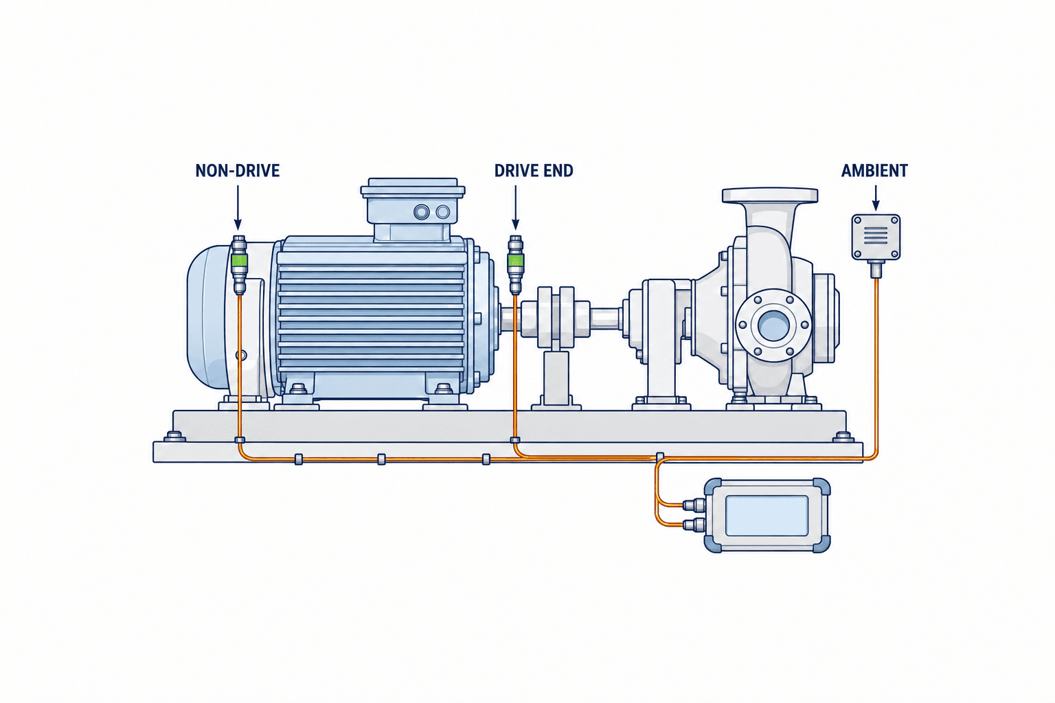
Define exactly where the sensor goes and what it measures
For a retrofit, a contact sensor on the outside of the bearing housing is a common option. Follow the OEM’s designated port where one exists; do not drill a housing on site without approval. Bearing internal temperature, housing surface temperature and nearby air temperature are different quantities. Do not assume that their difference is the same across machines. Write “drive-end bearing housing surface temperature” in the specification rather than just “bearing temperature.”
Check contact area, fastening, heat path, access for replacement and cable strain relief. A magnetic mount may help during a trial but needs separate assessment for permanent exposure to vibration and washdown. Route cables away from moving parts, heat, cleaning water and service access. Photograph and mark each point on the as-built drawing. Handheld infrared measurement can help survey candidate locations; readings depend on surface and sightline conditions. Treat it as a different method from fixed contact measurement.
Before installation, review OEM maintenance rules, warranty, guards, electrical safety, shutdown and restart procedures. OSHA’s hazardous-energy overview describes the danger of unexpected startup and stored energy during servicing. A Thailand project must follow the site’s applicable local rules and procedures, with contractor responsibilities assigned. A new sensor is not a reason to leave a machine guard removed.
Choose among Pt100, thermocouple, infrared and existing sensors
A Pt100 resistance temperature detector is a candidate for continuous trending over the relatively narrow range of a bearing housing. IEC 60751:2022 defines requirements for industrial platinum resistance thermometers and sensors. Compliance with a sensor standard does not establish the accuracy of the whole installed chain: thermal contact, leads, transmitter and calibration all matter. Specify wiring configuration for long runs. PTB’s resistance-thermometer guidance explains the influence of lead resistance in two-wire arrangements and the industrial use of three-wire arrangements.
A thermocouple may suit a hotter or wider range or an existing compatible input, but is not automatically better for a bearing housing. Check type, compensation, transmitter and panel capacity. Infrared tools allow non-contact surveys, provided surface condition and distance are controlled. Before buying a separate device, check for an OEM sensor or drive temperature channel. A Siemens drive catalogue lists distinct Pt100 monitoring options for winding and bearing temperatures. An existing “motor temperature” tag may refer to the winding, not the bearing.
| Method | Useful role | Procurement question |
|---|---|---|
| Contact Pt100 | Continuous housing trend | Mount, lead configuration, transmitter, replacement |
| Thermocouple | Higher range or compatible installed input | Type, compensation, leads, transmitter |
| Infrared rounds | Finding points and periodic comparison | Surface, distance, field of view, repeatability |
| Existing OEM sensor | Reusing a verified instrument | Physical point, tag meaning, access to values |
Collect operating context as well as temperature
Temperature alone can produce false alarms when process load rises. Collect running state and, where feasible, speed or drive frequency, a load proxy, ambient temperature and maintenance events. The load proxy may be motor current, flow or damper position, depending on the machine. Separate data needed for the alarm decision from data used later to diagnose a cause, so the pilot does not become an unnecessarily broad integration project.
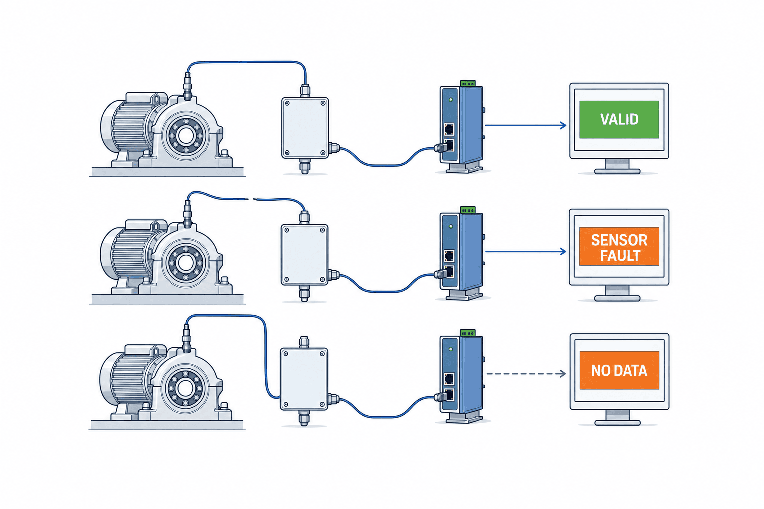
Each record needs a timestamp, asset ID, point ID, value, unit, quality flag and source. If communications fail, a last-known value must not appear as a current healthy reading. The interface and API should distinguish valid, missing, stale, out-of-range and sensor-fault values. Buffered data restored later is not a substitute for a real-time alarm that was unavailable during an outage. Define who responds when data are missing.
Time alignment matters. Did temperature rise before shutdown, or did a stopped machine soak heat into its housing? PLCs, gateways and servers with inconsistent clocks can reverse the apparent sequence. If a Japanese head office and Thailand plant share the dashboard, label the displayed and recorded time zones. Keep one source time basis for alarm logic rather than rewriting underlying timestamps for each viewer.
Set alarms by operating state and change, not one universal number
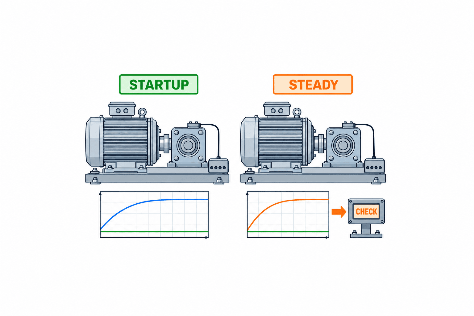
An instruction such as “email when the reading exceeds 80°C” ignores differences among assets and conditions. Build a normal-operation baseline for each point: stopped, warm-up, steady load, high load and post-cleaning conditions where relevant. The site, OEM and lubricant limits must guide protective upper bounds. No single temperature threshold can be recommended for every bearing in a public article.
Use at least a warning stage for inspection and trend review and a critical stage that requests an operating decision. If a signal is to stop the machine automatically, the OEM and control-safety owner must review it separately. An information-monitoring channel is not automatically a safety interlock. Sensor faults and communication delay must be designed into any protective function.
Candidate comparisons include difference from ambient, difference from a similar machine at the same load, and change from the point’s own same-load baseline. If combining absolute temperature and rate of change, avoid alarming on normal start-up warming. Define persistence before an alarm is confirmed and conditions for clearing it. Otherwise a reading around the boundary can flood staff with repeat messages. Review every week’s alarms as actual equipment issues, normal process changes, sensor faults or communication faults, then adjust with an audit trail.
Match each failure mode to a measurement and response
For an investment decision, break “protect the bearing” down into the failures that have actually affected the asset. A lubrication shortage that produced heat, contamination that first changed vibration and a cooling-fan fault that heated the whole motor may all appear in a shutdown log as “motor stopped,” yet call for different observations. If the maintenance record lacks a cause, develop a hypothesis from interviews and replaced parts, and label it as a hypothesis. An ROI case that assumes temperature will prevent every bearing failure will overstate benefits.
A useful failure-mode table lists whether a symptom can plausibly appear as heat, where it would appear, the time available for intervention, existing protective functions and additional checks. Heat may be an effect rather than the root cause. A blocked cooling path may raise the housing temperature along with the motor case. Looking at drive-end and non-drive-end points, motor case and ambient air can help distinguish a local bearing clue from broad heat load. It does not prove a cause: check current, airflow and other evidence. Narrowly defining what the sensor can diagnose makes its actual role clearer. A temperature alarm may initiate a vibration check, lubrication inspection or review of load and operating records rather than pronounce an automated diagnosis.
Separate sensor accuracy from the ability to detect a real change
The tolerance on a sensor datasheet does not specify the accuracy of the installed housing measurement. Poor thermal contact, a bracket that conducts heat away, cable effects, incorrect transmitter settings and stale calibration can all affect it. Agreement with a reference thermometer at one instant does not prove that the channel responds promptly to a changing load. Acceptance should separately test absolute agreement at a defined condition and repeatable discrimination of a change under comparable conditions.
Two probes may not fit on precisely the same physical point. Record the distance between them, surface treatment, contact pressure and measurement time, and avoid presenting the reference instrument as a perfect truth. Put the ambient sensor where it measures air rather than the motor’s exhaust heat. A more useful RFP request than a catalogue accuracy alone is the procedure for reproducing a comparison on site.
Faster sampling is not always better. Temperature often changes more slowly than vibration, and excessive data can burden networks, storage and screens. Yet sampling that is too slow can miss the window for action on a rapidly developing fault. Decide acquisition interval, history interval and alarm-evaluation interval separately from the failure mode and the time a person needs to respond. The time to report missing data deserves as much attention as a high-temperature threshold.
Govern changes so the alarm remains credible
An alarm tuned during commissioning may cease to fit when the bearing type, lubricant, drive speed pattern, production rate or sensor position changes. Capture such changes in the maintenance record and rebuild the baseline where appropriate. Do not let everyone change thresholds without a record. Keep the reason, old value, new value, approver and effective date. Distinguish a justified improvement from an undocumented threshold increase made to silence nuisance alarms.
A sensor replacement is also a measurement-system change. Preserve the logical point ID while recording the new sensor serial, calibration history, mounting condition and replacement time. If the reading steps after replacement, the team must be able to distinguish a machine change from an instrument change. Retain old sensor history and separate the physical sensor record from the logical point record; the same can be done in a paper log if needed.
Staffing and contact routes also change. A holiday recipient may have left the company, an email may be filtered or a phone may be muted. Periodic drills should create a test alarm and verify that the local person receives it, acknowledges it and creates the required maintenance record. Maintaining the measurement and maintaining the response process are two different duties.
Route alerts into maintenance work
An alarm sent to “all maintenance staff” may be owned by nobody. Assign a primary receiver, deputy, night and holiday coverage, acknowledgement deadline and work-order trigger per asset. A useful message contains the asset and point IDs, current reading, difference from baseline, running state, time of the latest valid sample and a link to the recent trend. “High temperature” alone wastes investigation time.
The response guide should distinguish a rise at steady operation, a rise that accompanies load, missing data and a post-repair drop under comparable conditions. A warning may prompt a check of lubrication and load; a critical condition may require a responsible person to review shutdown criteria. Do not simply raise the threshold when the cause is unknown. Record who received and acknowledged the alarm, the action, result and decision to return to normal. This history makes future baseline changes defensible.
Temperature data do not replace an asset-management record. Link bearing replacement, greasing, removal and root-cause investigation to the same asset and make the trend reachable from the work order. Our predictive maintenance implementation guide covers the wider program and cost structure. This article stays focused on turning a bearing-housing measurement into a maintenance decision.
Plan installation and communications for a Thailand plant
Survey spare cabinet inputs, power, cable paths, washdown, dust, oil, heat, electrical noise and maintainer access before selecting devices. A few wireless sensors may work in a pilot yet fail once metal stock moves or network loading changes. Wired options still need a shutdown window, panel design and separation from power cables. These practical constraints often decide total cost more than the sensor’s unit price.
Do not make the local first response depend entirely on a cloud connection merely because headquarters wants a remote view. Send only necessary status and history outside the site under the plant’s OT security rules. Test what continues locally during WAN loss. If battery-powered sensors are chosen, price the replacement work, low-battery warning and process to preserve point identity after exchange.
Local operators and head-office managers need different displays. Agree on units, time zones, asset names, message language and escalation authority. A translated dashboard alone cannot solve a night alarm that is routed to a day-shift employee. Match the notification roster to the actual Thai plant shifts.
Compare the cost of a functioning point, not just a sensor
Quoting “price per sensor” omits mounting, cabling, panel work, gateways, software, commissioning, training and recurring support. The same number of points can cost very different amounts when cable runs, available inputs, washdown conditions or shutdown access differ. Site quotes are needed before claiming a THB price. Fix the units of comparison instead of publishing an invented price.
| Cost layer | Include | Compare |
|---|---|---|
| Measurement point | Sensor, bracket, protection, calibration | Drive and non-drive ends counted separately |
| Equipment connection | Cables, panel input, power, gateway | Shutdown work, reusable tags |
| Data platform | History, quality flags, display, alerts | Retention and outage behavior |
| Operational rollout | Response guide, work orders, training, tuning | Owner of false-alarm review |
| Ongoing use | Recalibration, replacement, licences, support | Annual cost and spare availability |
For ROI, compile past bearing-related shutdowns, duration, restart cost, scrap, rework and maintenance hours by asset. Conservatively estimate which of those cases would create a temperature warning early enough for action. Do not credit temperature monitoring with preventing failures it cannot detect. Do not equate possible extra production with revenue or count the same saving twice. The first pilot should measure detectability, false alarms and response ability before asserting a payback period.
Write an RFP around points, data quality, alarms and support
Provide bidders with an asset and point list, photos, drawings, operating conditions, shutdown windows, existing panels and network constraints. Also state what is out of scope. Specify the surface being measured, range, required comparison quality, lead arrangement, calibration method and behavior for open circuit and out-of-range signals. A sensor catalogue accuracy figure does not ensure comparable readings after installation.
Define sample and record intervals, timestamps, missing-data flags, retention, CSV or API output, and PLC, SCADA or maintenance-system integration. For alarms, identify who sets baselines and thresholds, warning and critical levels, persistence, return-to-normal rules, recipients, acknowledgement, escalation and communication failure. Require a change history for settings. Include a replaceable-sensor procedure, spares, battery or network checks, recalibration, annual support and a fault contact. Ask suppliers to state who owns local installation and service in Thailand.
Test faults and missing data in FAT and SAT
In FAT, simulate normal, warning, critical, open-circuit, out-of-range, lost-communication and recovery states through the full path from input to screen, alarm and export. Check timestamps and quality flags. An initial threshold may be provisional, but the person responsible for final site tuning must be named. FAT cannot prove that the installed thermal contact or plant noise environment is acceptable.
At SAT, compare the as-built sensor location with drawings and compare readings under recorded load against an independent reference measurement. If readings differ, investigate contact, location, surface condition, response lag and operating state before declaring the sensor faulty. Test start and stop transitions, local delivery, acknowledgement and work-order creation. Following a power or network interruption, restored data must not silently become “healthy” current data.
Keep a test sheet with asset and point IDs, date, operating condition, simulated input, display, recipient, result, corrective item and retest sign-off. Handover should include calibration records, installation photos, wiring diagrams, tag and permission lists, backup and recovery instructions and training records. Separate conditions that can be tuned after baseline collection from safety and data-integrity requirements that must pass immediately.
A practical staged rollout
The following is an example sequence, not a universal fixed schedule. Select a few assets, review shutdown records, candidate points, responsible staff and installation safety. Take short-term manual readings under different loads before finalizing the RFP. Install the selected sensors, collection path, timestamps and quality flags, then run FAT and SAT. Do not announce “predictive failure” simply because values are streaming. Build an operating-state baseline and review false alarms and potential misses with maintainers each week.
Expand only after staff can separate sensor problems from machine problems and can respond within the available window. Comparing similar motors helps when their mounting and loads are comparable; otherwise a temperature ranking can mislead. Review acknowledgement rate, time from anomaly to inspection, false-alarm categories, missing-data rate and linkage to work records. A short pilot cannot be judged only by the absence of a failure. Keep examples where the signal helped and where it did not, then decide whether vibration or current is needed.
Frequently asked questions
Can a temperature sensor alone predict bearing failure?
No. Housing temperature is a useful clue but does not establish cause or remaining life. Early damage may not heat the housing. Combine it with operating context and, for important assets, other fault-specific measurements.
What alarm temperature should all bearings use?
Avoid one universal number. Use OEM and lubricant limits, ambient, load, speed, measurement position and the machine’s own history. A protective stop limit serves a different purpose from an inspection warning.
What determines the cost of a retrofit?
Mounting, cabling, panel work, communication, history, alerts, site tests and support often matter more than the device price. Ask for the cost of an operational measurement point and verify site constraints before comparing offers.
Should we use Pt100 or infrared measurement?
Contact Pt100 is a candidate for a permanent trend at a fixed housing point. Infrared tools are useful for surveying and repeat inspection when surface and sightline conditions can be controlled. OEM rules, installation safety and whole-chain accuracy determine the final choice.
Should a hot reading automatically stop the motor?
Separate monitoring notifications from machine protection. An automatic trip needs OEM and control-safety review, including sensor-fault behavior and process effects. Do not connect a new information channel to an existing protective circuit by default.
Conclusion
Motor bearing temperature monitoring becomes useful when the measurement point is fixed, operating context is recorded and a named person knows what to do after an alarm. Do not infer a fault from a single fixed temperature, hide missing data as normal, or confuse sensor catalogue accuracy with installed measurement quality. Specify points, quality, alarms and maintenance in the RFP; test faults, outages and real staff response in FAT and SAT. A small pilot that develops baselines and actions is more valuable than buying sensors for the whole plant at once.
If you are deciding where to measure existing motors and how to connect warnings to maintenance work, contact TOMAS TECH with an asset list and shutdown history. A discussion can start before the device type or number of points is fixed.


