



Selecting a machine vision lens starts with the inspection task, not a catalogue focal length or a “megapixel compatible” label. Define the field of view (FOV), available working distance (WD), smallest feature, workpiece height variation and acceptance method before comparing lenses. This guide concentrates on lens procurement for a factory in Thailand. Industrial camera body selection and inspection lighting design are covered separately.
Define the inspection job before selecting the lens
The first deliverable is an imaging requirements sheet for each station, not a part-number shortlist. Presence detection, code reading and dimensional measurement have different tolerances for distortion and magnification change. Quality, production engineering, maintenance and system integration should examine actual good, bad and borderline samples together. Describe the observable difference and keep the sample condition, handling and storage method with the request. A lens cannot reveal a defect that the complete imaging arrangement fails to make visible.
Record minimum and maximum part dimensions, placement variation, fixture tolerance and space around the inspection region. Note glossy, transparent, curved, printed and stepped surfaces separately. Add maximum line speed, available exposure time, front protective window, dust, cleaning spray, vibration and temperature. Agree on the illumination wavelength with the lighting engineer. If the project moves from visible to near-infrared light, focus position and transmission may need to be checked again against the exact product data sheet.
Keep optical acceptance separate from overall inspection acceptance. The lens affects image geometry and contrast; missed defects also depend on illumination, exposure, trigger, fixture, software and the distribution of real parts. A visually attractive image is less important than repeatable pass/fail decisions. Freeze a common sample set and compare candidate lenses under the same camera and lighting settings.
| Input | Specify | Why it matters |
|---|---|---|
| Task | Presence, reading, positioning or gauging | Sets distortion and magnification tolerances |
| Part | Dimensions, orientation, placement variation | Sets FOV and margins |
| Feature | Smallest mark, edge or defect | Sets object-side sampling target |
| Height | Thickness, warp, fixture tolerance | Informs depth of field and telecentric assessment |
| Working distance | Range from lens front to object | Sets optical and mechanical constraints |
| Sensor | Active width, height, diagonal, pixel pitch, mount | Determines coverage and resolution match |
| Illumination | Wavelength, filter, protective window | Defines optical test conditions |
| Factory | Speed, vibration, cleaning, maintenance | Defines mounting and locking needs |
If an input remains unknown, request proposals that state their assumptions and range rather than a single supposedly definitive lens. Revise all suppliers’ information against the same requirements version. A change in FOV or WD changes the comparison, so an RFP must identify which design assumptions have been frozen.
Calculate FOV, WD and focal length together
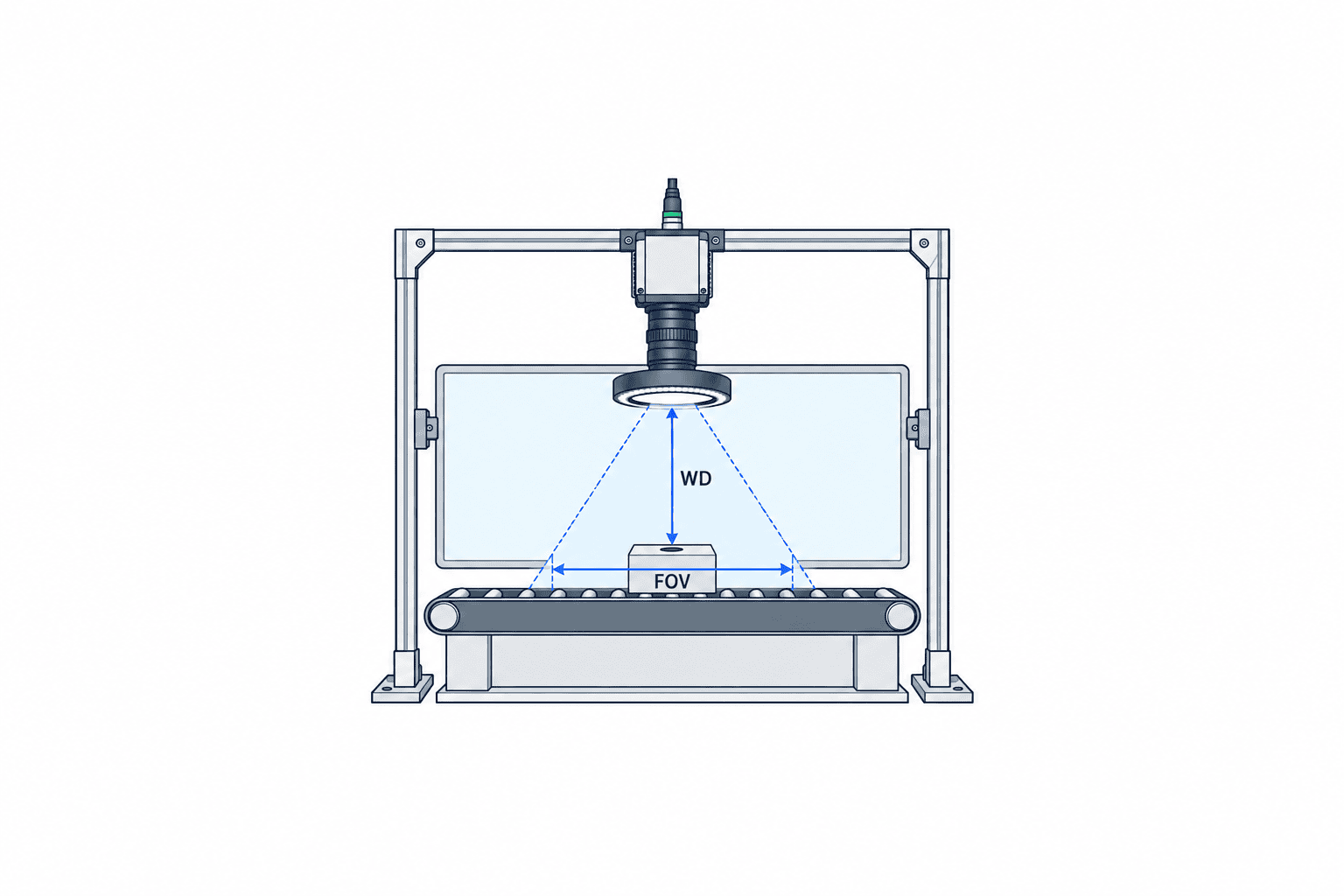
FOV is the area of the object captured by the sensor. WD is generally measured from the lens front to the object, not from the rear of the camera. Draw the camera axis, lens front, highest part position, conveyor and enclosure in one mechanical drawing. Define the distance origin explicitly. A focal-length estimate is useless if the proposed lens barrel or light ring collides with the machine.
Required FOV includes maximum part size, position variation and imaging margin. As an illustrative planning assumption, an 80 mm part plus 10 mm on each side needs a 100 mm horizontal FOV. This is not a recommended margin for every station. Test extreme part positions and orientations, including diagonal occupancy if a part rotates. Verify corners as well as the centre: the part must remain in frame and image quality must still be adequate there.
Edmund Optics’ imaging system calculator estimates focal length and magnification from sensor size, pixel pitch, WD and FOV. Its own notes describe the result as a paraxial approximation that omits principal planes and distortion. Use it to shortlist commercially available focal lengths, then confirm the actual lens’s focus range, minimum object distance, angular FOV and image through any protective window. Put the required FOV and WD in the RFP rather than only the calculated focal length.
Pixel sampling is not a detection guarantee
For an illustrative 100 mm horizontal FOV sampled by 2,000 horizontal pixels, nominal object-side sampling is 0.05 mm per pixel. A 0.10 mm line spanning two pixels is not automatically detectable. Defocus, lens contrast, illumination, colour filter interpolation, motion blur and processing all affect visibility. Edmund Optics warns that its object-space resolution output is a reference, not a performance guarantee. Determine the actual detection margin with borderline parts and the intended decision algorithm.
Use the active physical sensor dimensions from the selected camera’s data sheet rather than relying on a nominal sensor-format name. Check horizontal, vertical and diagonal coverage. If the camera uses ROI, binning or a colour sensor, record those settings because they change the useful sampling. Do not change camera settings between candidate lens trials without repeating the comparison.
Eliminate incompatible image circles and mounts first
The image circle must cover the active sensor to the required quality level. A matching mount thread does not ensure coverage; a small image circle can darken the edges and remove inspection information. Basler’s 2026 lens-selection guidance checks camera mount, image circle, focal length, sensor-matched resolution and aperture in sequence. Confirm maximum sensor coverage from the candidate’s specification, and evaluate the corner image where inspection needs it. Merely avoiding black corners is insufficient for gauging.
For C-mount and other interfaces, check the mount geometry, flange focal distance, adapters, filters and extension rings as a complete stack. Basler describes the C-mount flange distance as 17.526 mm; the exact camera and lens combination still needs verification in both manufacturers’ documentation. Adding an adapter can affect focus, vignetting and mechanical rigidity. Put each required adapter in the bill of materials. Schneider-Kreuznach’s optics toolkit offers a separate adapter-finder function, which illustrates why the connection is a design item.
Check barrel diameter, length, front element clearance and access to focus and iris locks. The light, air purge, window and cleaning tool need space too. A replacement lens may fit optically but fail mechanically on the installed bracket. For spare parts in Thailand, request both optical equivalence and physical interchangeability rather than assuming the same mount is enough.
Compare MTF under the same conditions
Modulation transfer function (MTF) shows how much pattern contrast an optic retains at a given spatial frequency. It varies with image position and test conditions. Schneider-Kreuznach’s MTF explanation shows why a curve must be read with its axes and field location. A centre result from supplier A should not be compared with an edge result from supplier B, or at different apertures, wavelengths or WDs. Ask for curves or sample images at the intended sensor, aperture, WD, wavelength, spatial frequency and centre-to-corner positions.
If the defect can appear near the image edge, a sharp centre alone does not meet the requirement. Evaluate actual borderline parts at all permitted positions and use the same display scale. A catalogue “megapixel rating” helps eliminate unsuitable products but does not prove usable contrast on a reflective factory part. This is why the real-sample image belongs beside the data sheet in the procurement record.
Fixed focal length versus telecentric lens
A conventional fixed focal length lens offers many options for presence checks, reading and positioning. Its perspective projection changes apparent size as an object moves toward or away from the lens. With controlled part height and a suitable fixture, that change may be acceptable or calibratable. “Fixed focal length” does not necessarily mean the focus ring is fixed; ask whether focus and iris can be locked after adjustment.
An object-side telecentric lens is designed to suppress magnification change over its specified object-height range. Basler identifies precise dimensional measurement as a common use case because perspective size changes can be reduced. This does not make telecentric optics universally superior. FOV, supported sensor, WD, depth of field, illumination, physical diameter and cost still have to fit the station. Do not assume a generic accuracy gain or price. Test the same calibrated target at the centre and corners, at the minimum and maximum allowed heights.
| Decision point | Conventional fixed focal length | Object-side telecentric |
|---|---|---|
| Common fit | Presence, reading, positioning, controlled-height gauging | Gauging with part-height variation |
| Height variation | Apparent scale can change | Designed to limit scale change within specification |
| Distortion | Check product curve and calibration need | Often low, but verify per product |
| Installation | Broad choice; confirm WD and mount | Check FOV, barrel diameter, WD and space carefully |
| Acceptance evidence | Defect visibility and repeatability | Reference-part error over field and height |
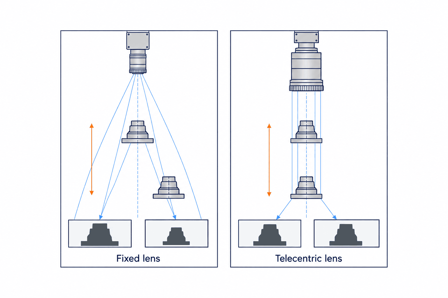
Define required measurement uncertainty and the height range the fixture cannot remove before paying for telecentricity. If a conventional lens plus fixture and calibration passes the same acceptance plan, it remains a valid candidate. If height-dependent scale change dominates error, a telecentric trial has a documented reason. Keep the camera, lighting and evaluation method identical during the comparison.
Can software distortion correction solve it?
Distortion displaces image coordinates differently across the field. Edmund Optics’ distortion note explains wavelength and WD dependence and the difference between geometric and TV distortion figures. Compare numbers only when their definitions and conditions match. Image a dot or grid target across the full usable field, measure residual error after correction and check whether correction affects cycle time or decisions. A single advertised “0% distortion” figure does not describe all field positions.
Correction assumes stable calibration. Require recalibration after a lens replacement or changes to focus, WD, wavelength or camera angle. Save the target certificate, image orientation, temperature and processing version. Software correction cannot recreate detail that the optical system did not resolve. Treat calibration, lens resolution and height-dependent magnification as related but distinct design questions.
Balance aperture, depth of field and lighting in one trial
Opening the iris admits more light but changes depth of field and sometimes edge quality. Stopping it down helps depth of field, yet longer exposure can blur a moving part and excessive stopping down increases diffraction. Run trials at the intended line speed with the lowest and highest part positions. Record iris setting, exposure, strobe timing and real illumination. A supplier’s ideal MTF condition may differ from the factory’s working setting.
Select lens wavelength coverage and filters with the lighting design. A change from visible to infrared illumination or addition of a protective window can alter focus and reflections. Confirm that the ring light fits the barrel and does not reflect in the window. Assign one owner to the complete imaging condition even if camera, lens and light are purchased separately. The dedicated lighting guide addresses methods for making the defect visible.
For a high-speed line, footage of moving borderline parts matters more than a beautiful static image. Compare candidates at the same exposure, trigger timing and conveying orientation. Lock focus and aperture, then test whether vibration or cleaning shifts them. Include day and night shifts, product variants, and images just after cleaning in SAT when those conditions affect the station.
What a Thai-factory lens RFP should request
An RFP should make suppliers propose and test against the same conditions. Provide real good, bad and borderline parts, subject to agreed confidentiality, sample return and image-use rules. If borderline parts are rare, use clearly labelled surrogate samples and state their limits. A photograph alone may not reproduce gloss, transparency or microtexture; ask for physical samples or a site imaging trial.
Specify FOV and WD ranges; camera model, active sensor and mount; wavelength; object-height range; smallest feature; throughput; enclosure; and window or filter. For each proposed lens request aperture recommendation, image-circle support, MTF and distortion test conditions, focus and iris locking, adapters and bracket drawings, maintenance method and replacement arrangements. Compare total installed scope including fixtures, calibration, commissioning and spares, not just the lens line item. Mark untested claims as “to be verified” rather than treating estimates as warranties.
| RFP field | Minimum content | Evidence to receive |
|---|---|---|
| Task | Gauging, presence or reading and limit samples | Original images of sample set |
| Geometry | FOV, WD, height limits, sensor diagonal | Layout and optical configuration |
| Image quality | Minimum feature across usable FOV | Centre and corner images with settings |
| Metrology | Allowable error and calibration method | Certified target and residual table |
| Mechanics | Envelope, locks, window, replacement process | CAD, bill of materials and procedure |
| Operations | Spare, training and change control | Maintenance plan and local instructions |
Issue questions and answers to all bidders on the same revision. Otherwise suppliers may quote different part drawings and their prices are not comparable. Specify Thai-language maintenance instructions when required on site and an English or Japanese test record for the regional quality team. Ask suppliers to state delivery and replacement conditions at the proposal date; do not assume a particular local stock position will remain true.
Keep evidence and quoted claims in separate columns
For each candidate, separate the maker’s published value, the distributor’s response and the measured result on your parts. A claim of “low distortion” needs its FOV, wavelength, WD and definition. MTF curves need matching test conditions. Record the response date for lead time and warranty and reconfirm before ordering. Keep mandatory measurement limits as pass/fail gates; a low purchase price should not make an otherwise nonconforming lens acceptable.
Track the lens model and lot, camera settings, light, bracket and calibration file as one controlled configuration. If another lens may be substituted in production, qualify it with the same limit samples and residual measurements. Standardize the bracket position and focus-lock method so subsequent machines can reproduce the first station’s performance, including after a transfer to another Thai site.
Build a lens-specific acceptance matrix
Expressions such as “good image quality” and “measurement possible” do not say what to test in FAT and SAT. Alongside system-level pass/fail results, create a matrix for optical and installation factors. The following is a format example; every numerical pass limit must come from the product tolerance and inspection goal of the particular factory. If a station is planned around an illustrative 80 mm-wide part plus placement margin and therefore a 100 mm horizontal FOV, write that design assumption in the FOV row, with the selected sensor, imaging height, product variants and extreme part positions. The 100 mm figure is an example, not a standard FOV for other products.
| Lens-side check | FAT evidence | Extra SAT check | If it fails, separate these causes |
|---|---|---|---|
| Full FOV | Original images of largest part at extreme placement | No clipping at corners during production movement | Fixture position, WD and focal length |
| Smallest feature | Good, bad and borderline parts at same exposure | Repeat at line speed and after product changeover | Focus, iris, light and motion blur |
| Corner quality | Reference target at centre and four corners | Repeat through actual protective window | Image circle, window reflection, camera angle |
| Gauging residual | Calibration grid and reference-part measurements | Recalibrate and repeat at same site positions | WD, distortion correction, scale change |
| Holding and repeatability | Image after locking adjustment rings | Image after vibration, cleaning and restart | Locks, bracket and replacement procedure |
For every row, record sample ID, camera and lighting settings, lens model and serial number, capture time and reviewer, as well as the pass criterion. If JPEG compression could obscure a fine scratch, preserve the original capture format separately from processed output. For measurement, associate each reference-part reading with the calibration-file version. Keep passing borderline images too: they become a reference when the factory builds a second station.
If FAT produces a failure that might come from the lens, light or fixture, hold all but one condition constant and recapture before replacing hardware. Dark corners may reflect a small image circle, but a window reflection, lighting geometry or mechanical vignetting can also be responsible. A dimensional shift only when part height changes may involve part tilt, WD, calibration plane or lens magnification. After isolating a cause and applying a correction, use the same borderline samples and the same matrix for the retest. Switching samples while declaring an improvement changes the acceptance basis.
SAT should also leave a test that the factory can repeat daily. Detailed measurements with a calibration target belong at commissioning and after component replacement; daily checks can use representative borderline parts, focus-position marks, light condition and all four image corners. Decide ahead of time when operators must stop the station, which lots quality must recheck and when maintenance recalibrates. This connects optical acceptance to ongoing production control.
An acceptance matrix needs more than an instruction to “inspect.” Do not issue the purchase order with an empty pass-limit cell; name who will derive the value from which customer or quality requirement. In gauging, do not assign the entire product tolerance to the lens alone: consider the error budget for fixture, calibration and image processing. In presence detection, name the borderline samples for false negatives and false positives. Agree the evidence format, retest rules and final sign-off owner before installation, so the site team does not have to renegotiate what “pass” means.
At commissioning in Thailand, decide where images and the acceptance matrix will be stored. Files kept only on the machine PC can be lost when equipment or staff changes. Under the factory’s access rules, index them by product model, station number, capture settings, test date and approved revision. Keep original captures so contrast or distortion processing can be repeated; restrict access if the image contains customer product information. Months later, an approved borderline image captured under comparable conditions is the starting point for investigating a change in rejection rate.
Make responsibility for the matrix explicit. If the camera, lens and light come from separate suppliers, a dark image, blurry corners or a dimensional shift cannot automatically be assigned to one company. The system integrator should lead testing of the combination; each manufacturer supplies component specifications and test conditions. Assign machine engineering to bracket rigidity and position, and quality to limit samples and decision thresholds, with an owner and contributors for each test row. Sharing these roles in the RFP reduces the chance that an unresolved FAT issue is deferred to SAT.
Accept the lens through FAT and SAT
Factory acceptance testing (FAT) happens before shipment; site acceptance testing (SAT) happens after installation. Agree the acceptance plan before purchasing. Freeze camera, light, aperture, WD and processing version; use the same reference and borderline samples. Photograph the centre, corners, extreme part positions and height limits at production speed. Passing a focus adjustment is not a pass for the inspection task. For gauging, retain the reference target certificate and measured residuals against the specified tolerance.
A successful FAT cannot prove the effect of site vibration, ambient light, mounting angle, air lines, protective window or cleaning. At SAT, collect stopped-line and running-line images under representative products and shifts. Check focus and iris locks, bracket repeatability, cable routing and restart after cleaning. Record numerical limits or explicit decision rules, the owner of any open item and the retest date. “The image looks good” is not an acceptance criterion.
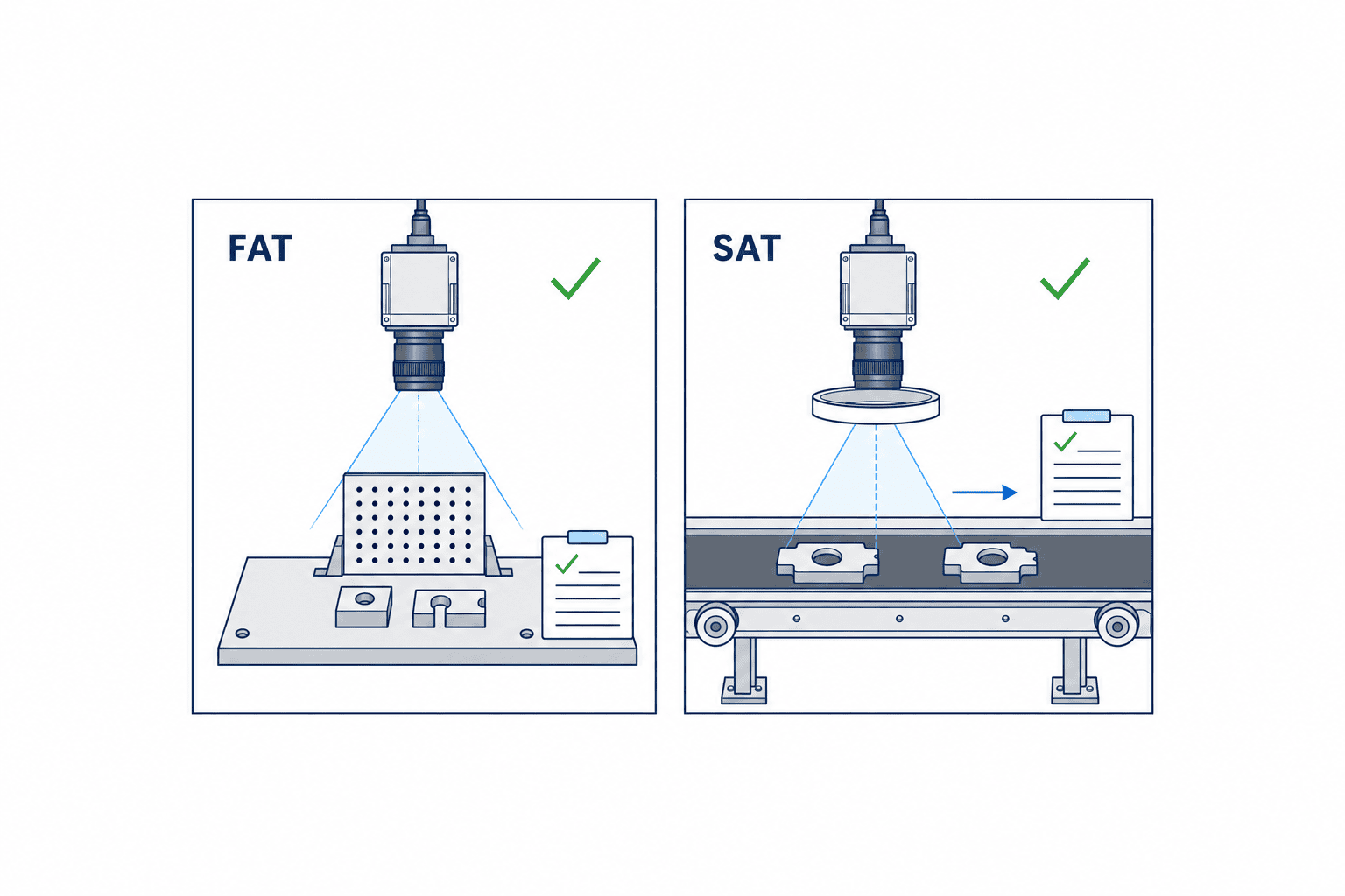
Archive passing borderline images as well as failures and original captures. When rejection rates rise later, the team can distinguish a dirty lens, aged light, focus drift, placement change and product revision. Maintenance should repeat calibration and limit-sample tests after lens replacement, even for the same model. Procurement is complete when the factory can sustain the qualified imaging condition.
Frequent procurement mistakes
A high-pixel-count camera does not prove that the lens resolves corners or covers the sensor. A calculated focal length does not prove that barrel length, WD origin and window fit the enclosure. Software distortion correction does not remove the need to check residual error and processing time after configuration changes. A telecentric lens does not eliminate its FOV, diameter, light and space limits. Prevent these failures by requesting real-part test evidence against each critical specification.
Also define words precisely across the optical, machine and quality teams. “Accuracy” might mean pixel pitch, repeatability, absolute dimensional error or inspection classification. “Resolution” can mean sensor pixels or lens spatial frequency. Give each inspection item a unit, calibration method or pass/fail limit as appropriate. For commissioning in Thailand, a short illustrated glossary of FOV, WD, magnification and distortion helps engineers using different languages agree on the same geometry.
A practical machine vision lens selection sequence
First agree the observable feature using real parts and borderline samples. Next set FOV from part dimensions and placement range, and WD from the machine drawing. Confirm active sensor size, pixel pitch and mount, then calculate a candidate focal-length range. Eliminate incompatible image circles and mechanics; compare MTF, distortion, aperture, wavelength and availability. Photograph identical parts with conventional and telecentric candidates where measurement error justifies the comparison. Finally freeze test conditions in the RFP and preserve FAT and SAT evidence.
The process does not end when a part number is chosen. The factory must be able to recreate the qualified condition after cleaning, changeover and replacement. You do not need a perfect specification before contacting an integrator; disclose the unknown inputs and ask for a trial that creates comparable images under controlled conditions.
FAQ: industrial camera lens selection
In what order should FOV, WD and focal length be decided?
Set the FOV from the object and its placement variation, then set the available WD from the machine layout. Enter the active sensor dimensions to estimate focal length. Confirm with the lens data sheet and real imaging, rather than ordering from the equation alone.
Is a telecentric lens mandatory for dimensional inspection?
No. Decide from allowed error, unavoidable part-height variation and residual error with a conventional lens and calibration. A stable fixture may make a conventional lens acceptable; height-dependent magnification may justify a telecentric trial.
Does the same “megapixel compatible” label mean equal image quality?
No. MTF across the image, spatial frequency, aperture, WD, wavelength and pixel pitch matter. Use the rating to shortlist products and compare original images of borderline parts.
Can SAT in Thailand be skipped after FAT passes?
No. FAT does not test the site’s vibration, ambient light, mounting, window and cleaning. Repeat reference-sample tests during SAT at production speed and under representative shifts and product variants.
Conclusion
Select a machine vision lens by aligning FOV, WD, active sensor, pixel pitch and image circle, then verifying MTF, distortion, aperture, height variation and physical installation with real images. Compare conventional and telecentric options against the same acceptance error. An RFP with test conditions and evidence, followed by both FAT and SAT, helps avoid costly rework after the station reaches Thailand.
If your team knows the part and available camera space but has not yet settled the lens shortlist or acceptance plan, contact TOMAS TECH. We can start with the drawings and samples you already have and define a fair imaging comparison.


