


Choosing a radar level transmitter for a factory tank in Thailand starts with the tank’s duty, liquid and operating conditions, not a choice between frequency labels. A reading used to replenish a raw-material tank has different consequences from one used to stop filling or protect a pump. This guide turns those differences into a practical specification: compare non-contact and guided-wave radar, check the nozzle and beam path, validate echoes on the actual tank, and put acceptance tests into the purchase order.
Start radar level transmitter selection with a tank conditions sheet
Radar sends an electromagnetic signal towards a material surface and calculates the distance from its return. The tank reference point and geometry turn that distance into a level. A catalogue range alone does not tell you whether the return will remain usable in a vessel with an agitator, foam, condensate or a narrow nozzle. Endress+Hauser’s guide to continuous level measurement recommends collecting application data before choosing the measurement principle.
Record the tank ID and purpose; liquid name, concentration and changes; normal and extreme temperature and pressure; height and shape; nozzle drawing; fill and discharge points; coils, ladders and agitators; foam, vapour and condensate; power and PLC inputs; maintenance access; and the consequences of a missing or implausible reading. Include the worst credible production state, not just a calm tank during a site visit. Use the same signed conditions sheet for each vendor.
| Question | What to document | Why it matters |
|---|---|---|
| What decision uses the reading? | Inventory, refill, control, dry-run prevention, high-level alarm | Defines update and failure behaviour |
| What is in the tank? | Media and composition changes | Affects echo strength, coating and material compatibility |
| What is the process envelope? | Temperature, pressure, foam, steam, condensation | Defines the operating case to prove |
| Where can the device sit? | Tank and nozzle drawings, internal structures | Determines the beam path or probe clearance |
| Where will the value go? | PLC, SCADA, output and diagnostic requirements | Determines scaling and integration work |
This sheet also catches disagreements between purchasing and maintenance. A liquid described as “water” may be replaced with cleaning solution once a month. A quiet surface may become highly turbulent directly under the inlet. Confirm hazardous-area approval, hygienic requirements, wetted materials and local regulatory needs for each application; a general article cannot set these project-specific requirements.
Non-contact radar versus guided-wave radar
Non-contact radar looks at the surface from an antenna above it. There is no immersed probe to foul, clean or protect from a mixer. Its path, however, can see the nozzle, wall or internal hardware instead of the desired liquid surface. Foam and condensate on the antenna may also matter. “Non-contact” does not mean every vessel can be measured without maintenance or testing.
Guided-wave radar carries the signal along a rod or cable. Endress+Hauser describes it as a useful option for turbulent surfaces, foam, obstacles and interface measurement. The tradeoff is the physical probe: verify contact with the process, buildup, corrosion, cleaning, installation length and mechanical clearance from moving parts. Decide which set of constraints is easier to manage in the particular tank.
| Tank condition | Check for non-contact radar | Check for guided-wave radar |
|---|---|---|
| Agitation | Can the beam avoid the shaft and blades? | Can the probe avoid mechanical contact? |
| Foam | Will it track the liquid surface or foam top? | Will the probe and signal remain usable? |
| Viscous product | Will the antenna accumulate coating? | Can the probe be cleaned and removed? |
| Narrow vessel | Can the beam avoid wall reflections? | Is there room for the probe and clearance? |
Avoid a blanket statement that radar either “works with foam” or “cannot work with foam.” The Rosemount 1208A manual says light airy foam may allow measurement of the actual liquid, while heavy dense foam may lead the device to read the foam surface. First specify which surface the process actually needs. Then test the worst foam condition or mark it explicitly as unverified.

When is an 80 GHz radar level transmitter a good choice?
Many 80 GHz designs focus a narrow beam. VEGA’s published sulfur-melting-tank case used that characteristic to aim between the vessel wall and an agitation rod. That is an instructive installation example, not a performance guarantee for another medium or tank. Endress+Hauser states that free-space radar accuracy depends on a combination of dielectric properties, frequency, antenna, beam angle and installation; its 80 GHz application note also identifies cases where 26 GHz, 6 GHz or another measurement principle may be preferable.
A narrow beam can make a clear path around obstructions possible. It cannot, by itself, solve dense foam, an antenna covered in condensate, poor reflection from the medium or a badly aligned nozzle. The stated maximum range is only one check. Ask about the near-zone exclusion, the level near the tank bottom, response during filling, and how signal confidence changes across the process envelope. Compare candidates under the same test conditions rather than ranking a single datasheet accuracy number.
Five checks before fixing a non-contact level transmitter to a nozzle
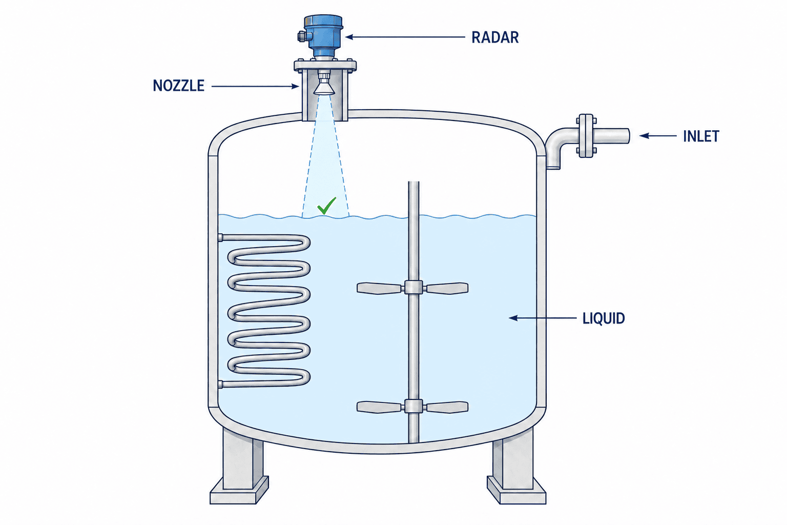
First, draw the beam from antenna to liquid surface at high, middle and low level. Emerson’s installation guidance advises keeping heating coils, ladders and agitators outside the radar beam because they can create false echoes. Signal processing may suppress those echoes, but a cleaner physical path is preferable when available.
Second, compare the existing nozzle’s diameter, height, protrusion and tilt with the actual product’s mounting instructions. A familiar flange size is not proof that the antenna is correctly installed. Obtain approval against a section drawing before fabrication.
Third, keep the beam away from the inlet stream and inspect normal agitation, immediately after ingredient addition, and near the end of discharge. The easiest operating state must not stand in for the hardest one.
Fourth, plan maintenance access. Identify the safe platform, antenna inspection and cleaning method, cable route, display position and whether replacement requires draining the tank. Use the tank number, instrument tag and drawing revision consistently across Japanese, Thai and English handover documents.
Fifth, define the relationship between continuous measurement and protective functions. If the same measurement is used to trigger a high-level alarm, the designer must assess what happens when that instrument fails. Functional-safety or independent protection requirements need project-specific engineering and manufacturer confirmation.
Write dielectric, foam, condensation and mixing conditions into the specification
Echo strength is linked to the dielectric contrast between the vapour space and the product. Maintenance staff may not know a precise dielectric constant, but can describe the product, concentration, temperature and changes of recipe. That is more useful to a vendor than “liquid, general service.” Endress+Hauser’s measurement primer also identifies antenna condensation and foam as conditions that can affect free-space radar.
Specify whether “level” means the actual liquid beneath foam or the foam top. Include the period of maximum foam in the test plan, with an independent reference method. If that state cannot be produced during commissioning, record who will repeat the test and when. Check condensation after cooling and cleaning cycles, not only during steady daytime operation. Select the antenna and cleaning arrangement from the product instructions.
Capture echo curves with the tank almost empty and while running. Emerson describes technology that tracks and suppresses multiple false echoes from internal objects, but this does not remove the need for a sound mounting location or an on-site acceptance record. Save the original and adjusted settings, so future maintenance can compare the signal after buildup or a tank modification.
Integrate the level reading with PLC and SCADA
Separate instrument accuracy from the uncertainty of the value used by the plant
The accuracy stated in a catalogue is measured under specified test conditions. The level shown to an operator also depends on the reference point, actual tank dimensions, nozzle alignment, surface movement, PLC scaling and filtering. A level-to-volume table adds another source of error. Do not assume that an instrument’s accuracy figure transfers unchanged to inventory accuracy. Identify which source of error dominates in the installed system before comparing datasheet figures.
Agree on the acceptance reference before testing. A manual dip, an existing instrument and a known quantity added to the tank each have limits. Record the reference method, simultaneous reading, surface condition and device configuration, so a discrepancy can be investigated. Set the numerical pass criterion from the process purpose—inventory display or active control—instead of applying one universal tolerance.
A single matching reading is not proof of continuous performance. Compare low, middle and high levels, and rising and falling level where feasible. Separate foamy from foam-free conditions and a running mixer from a stopped one. Record interruptions, jumps and excessive lag as well as level difference. If normal production cannot be tested at commissioning, mark the case unverified and assign an owner and method for checking it during first operation.
If a reading is wrong, trace the chain before replacing the transmitter: independent actual level and reference point, echo curve and device distance, then 4–20 mA current, PLC scaling and SCADA display at the same time. A correct radar distance can be turned into a wrong screen value by reversed scaling; a correct level can become wrong inventory through an old volume table. Include this diagnostic order in the SAT procedure so the instrument and control teams can locate the fault together.
For a 4–20 mA loop, define which physical levels map to its endpoints and what the PLC displays for a broken cable or device fault. Siemens’ SITRANS LR110 manual documents 4–20 mA/HART and configurable fault-current behaviour for that specific model; verify output and diagnostics for whichever candidate is proposed. If volume is displayed, record the separate level-to-volume conversion for a non-uniform tank.
Distinguish the instrument’s measurement update, the PLC filter, the historian interval and dashboard aggregation. Raw-material stock reporting and fast filling control do not need the same time resolution. Our factory IoT sensor selection guide explains how to start with the decision and sampling period. The factory IoT implementation guide covers the data and cost layers beyond a single instrument.
Consider invalid data as well as high and low values. Who notices a lost echo, a broken loop or missing history? Who performs a manual check, and what action follows? A working analogue value is not a complete monitoring system unless those questions are answered.
Make quotations comparable through a common RFP
Send each supplier the same tank conditions and request a proposed mounting position and a fallback option. Ask them to state what is included: transmitter, antenna, process connection, nozzle work, wiring, configuration, PLC changes, commissioning, training, spares and local support. A low price can simply represent a smaller scope.
The RFP should name the level range and non-measurable zones, medium and process extremes, internal obstructions, output and fault behaviour, test evidence, drawings, languages for handover, and the corrective action if acceptance fails. Do not set an arbitrary universal tolerance. Inventory reporting and fill-stop control may value different error, response and availability characteristics.
Change “How much is an 80 GHz unit?” to “For this tank and its fill, mix and cleaning conditions, propose a beam path, device and acceptance test.” This gives vendors room to propose the right frequency while keeping their assumptions visible. Ask for both reuse of an existing nozzle and a new-nozzle option where relevant.
FAT and SAT: prove configuration and actual operation separately
Factory acceptance testing can check the ordered model, output, settings, simulated PLC signal and documentation. It rarely reproduces real foam and every tank obstruction. Site acceptance testing checks the installed reference point, displayed level against a known or independent reading, and behaviour at several level points and operating states. Include filling, discharge, mixing and cleaning transitions where possible.
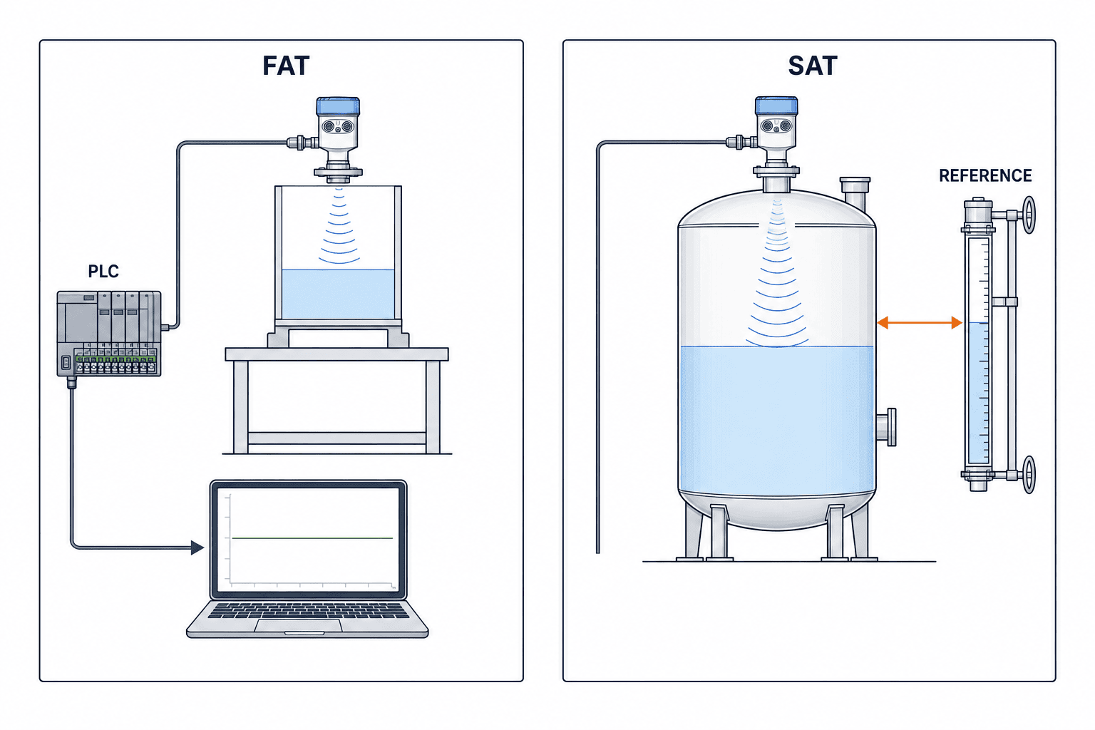
Keep an acceptance record with timestamp, process state, reference measurement, instrument reading, echo curve, settings revision and sign-off. Preserve a normal echo curve as a maintenance baseline. If a state cannot be tested, label it “not verified,” assign an owner and set a later check. Pass, conditional pass and unverified are distinct findings.
For the first operating weeks, trend the value and count missing readings. Review a frozen or implausible value as carefully as an obvious loss of signal. If settings are changed, record the reason and before-and-after curves; do not quietly alter alarm thresholds. Compare quotations across installation and acceptance scope, not only instrument price.
Handover in a Thai factory
Leave room for extensions and instrument replacement
Even a one-tank project may later gain adjacent tanks, altered piping or a different roof walkway. Mark a sensible future cable path, spare PLC input policy and tag-naming convention on the layout, while separating essential first-phase purchases from optional future capacity. Also keep a configuration backup and a normal echo curve in the asset record. Replacing a failed transmitter requires restoring the reference point, range, false-echo settings and output scaling for the actual model and software revision, then checking the result against a known on-site level. A new device is not automatically an equivalent measurement.
The plant designer, local contractor, maintenance team, Japanese head office and instrument supplier may work in different languages. Shared identifiers—tank ID, tag, nozzle, terminals, drawing revision and reference point—reduce ambiguity more reliably than a translated adjective such as “high.” Give maintenance the normal echo curve, troubleshooting order, antenna inspection method, configuration backup and vendor contact. Give operators the rule for an unreliable reading and when to request a manual check.
Also settle spare-unit lead time, local configuration help and the procedure for replacing the instrument before a failure occurs. Even a one-instrument project benefits from a named support owner.
Frequently asked questions about radar level transmitter selection
Does 80 GHz always improve accuracy?
No. A narrow beam can help avoid obstructions, but accuracy also depends on the product’s dielectric properties, antenna, nozzle, mounting and process conditions. Ask for evidence under the actual tank conditions.
Can we reuse an existing nozzle?
Possibly. Check its dimensions, beam direction, fill stream and the candidate’s installation manual. Compare the cost and measurement risk of reuse against a new nozzle.
How do we compare guided-wave radar?
Compare non-contact beam and antenna constraints with guided-wave probe contact, coating, mechanical clearance and cleaning. Define whether the process needs liquid level, foam top or an interface.
Can radar measure through foam?
Sometimes, depending on foam properties and the instrument. Light foam may allow an actual-liquid echo; dense foam may make the device see the foam top. Test the worst operating state.
Is a full FAT/SAT process necessary for one transmitter?
The paperwork can be short, but a conditions sheet, acceptance criteria and recorded checks are still needed. One incorrect reference dimension or PLC scaling value can make an otherwise good instrument unusable.
Summary
Radar level transmitter selection is a comparison of measured duty, medium, tank geometry, internals, foam, condensation, mounting, integration and maintenance. An 80 GHz beam may be advantageous, but other frequencies or guided-wave radar may fit better. Draw the path, capture the echo, agree on FAT and SAT criteria, and keep the evidence with the asset.
If your tank conditions are still being documented, TOMAS TECH can help organise the measurement requirements, mounting alternatives and PLC/SCADA scope before a device is ordered. You can contact us at that early stage.
Sources
- Endress+Hauser, Continuous level measurement in liquids
- Endress+Hauser, Is 80 GHz radar right for your process?
- Endress+Hauser, Frequency and antenna selection
- Endress+Hauser, Guided radar level measurement
- Emerson, Rosemount 1208A Reference Manual
- Emerson, Smart Echo Supervision
- VEGA, 80 GHz radar in sulfur melting tanks
- Siemens, SITRANS LR110 Operating Instructions


