


When a control panel in a Thai factory switches a heater, lamp, or solenoid, choosing a solid-state relay (SSR) by current rating alone can overlook off-state leakage, start-up damage, and heat buildup. SSR selection starts with two separate circuits: the PLC or controller input, and the AC or DC load output. It then considers turn-on method, steady and inrush current, thermal design, protection, and on-site tests. This guide gives engineering and procurement teams a practical sequence for specifying the device. Ratings quoted by a manufacturer apply to its stated conditions, not automatically to every control panel.
At a glance: Match the SSR output to the load supply and current waveform, and the SSR input to the controller output. For AC loads, choose zero-cross or random turn-on according to the application. Derate current against the actual cabinet ambient temperature and heat sink installation. An SSR can pass leakage current when “off”; it is not a maintenance isolator or a complete safety stop. Confirm the final choice against the exact product datasheet and the installed machine. Panasonic usage cautions; OMRON technical guide.
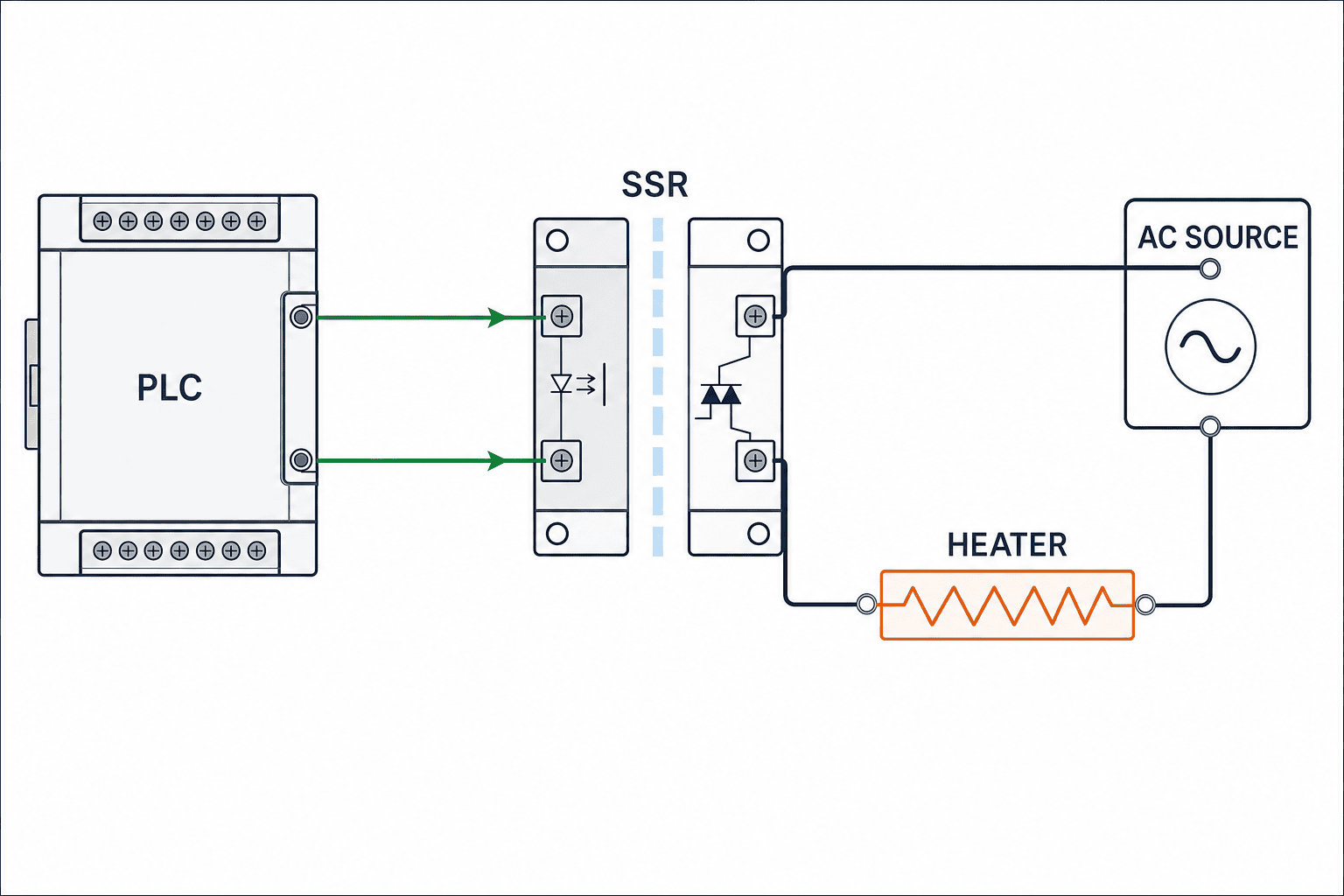
1. Define the input and load output separately
An SSR receives a control input and switches a separate load circuit through a semiconductor output. Models differ in input voltage, AC or DC output, switching behavior, packaging, and thermal requirements. A 24 V DC PLC output does not imply that the load requires a DC-output SSR: the PLC might command a single-phase AC heater. Write the input conditions and the load conditions as separate lines in the request for quotation. For the input, record the PLC output type, voltage range, available current, polarity, and the number of SSRs driven together. For the output, record supply voltage and range, frequency or DC polarity, phase count, load type, steady current, and measured or specified start-up waveform. OMRON guide.
This is a different selection problem from a mechanical contactor. The absence of moving contacts removes contact wear, but semiconductor losses generate heat and an off SSR may leak current. Surge, short circuit, or heat may damage the output. A failure can therefore have a different symptom from a worn mechanical contact. For high-inrush motor loads, compare the intended switching role and protection with our magnetic contactor selection guide. When an SSR is driven by a temperature controller, see our separate temperature controller guide for controller functions; this article stays with the SSR hardware.
2. First branch: AC or DC load?
Check the load nameplate and circuit drawing before reviewing an SSR catalog. An AC-output unit should not be assumed suitable for DC simply because its voltage number looks close, nor should a DC-output unit be wired to an AC supply. Verify the operating voltage range, frequency, phase arrangement, and nature of the load, including the voltage at start-up and during supply transfer. A current and voltage rating alone does not establish compatibility with every load. OMRON technical guide.
For DC inductive loads, polarity and coil flyback matter. Panasonic notes that inductive spikes at a DC SSR output must be limited if they exceed maximum ratings, and illustrates clamp and snubber approaches. The suppression method may also change how quickly a valve releases, so verify the required release time on the machine. For AC loads, look at surge, power-factor or phase shift, and whether the candidate includes a snubber. Protection components vary by model and are not a generic add-on. Panasonic usage cautions.
For a three-phase heater, specify how each phase is switched, how a missing phase is detected, fuse arrangement, and the load connection. Three unrelated single-phase SSRs should not be treated as an automatic substitute for a designed three-phase arrangement. The factory being in Thailand does not itself set an SSR rating; the cabinet’s actual temperature, dust, moisture, available spare parts, and service access do. Measure or specify the worst credible cabinet condition rather than inferring a rating from outdoor weather.
3. Zero-cross versus random turn-on
Many AC SSRs use zero-cross turn-on: after an on command, the output begins to conduct near an AC voltage zero crossing. A random turn-on device can conduct without waiting for that crossing. OMRON explains how zero-cross switching can reduce noise as current rises, and gives lamp inrush as an example. That does not mean zero-cross is universally the lowest-inrush option for transformers or phase-shifted loads; their magnetic or current behavior must be evaluated separately. OMRON zero-cross explanation.
For a resistive heater switched in relatively long bursts, zero-cross is often a sensible candidate. If the controller needs conduction at a chosen phase angle, evaluate a compatible random turn-on device and controller, with attention to electrical noise and equipment compatibility. An SSR-drive output on a temperature controller does not, by itself, specify the SSR turn-on method or authorize phase-angle control. Check the controller output mode, cycle time, heater characteristics, and wiring together. Our temperature controller guide covers the controller side.
For inductive loads, voltage and current may not cross zero together. Panasonic cautions that phase-shifted loads can cause an AC triac to fail to turn off as expected or a zero-cross type to fail to turn on, and asks users to test actual equipment. Select in this order: identify the load, specify the required switching behavior, examine the noise and inrush waveform, then test the actual assembly. Panasonic usage cautions.
4. Check repetitive inrush, not just running current
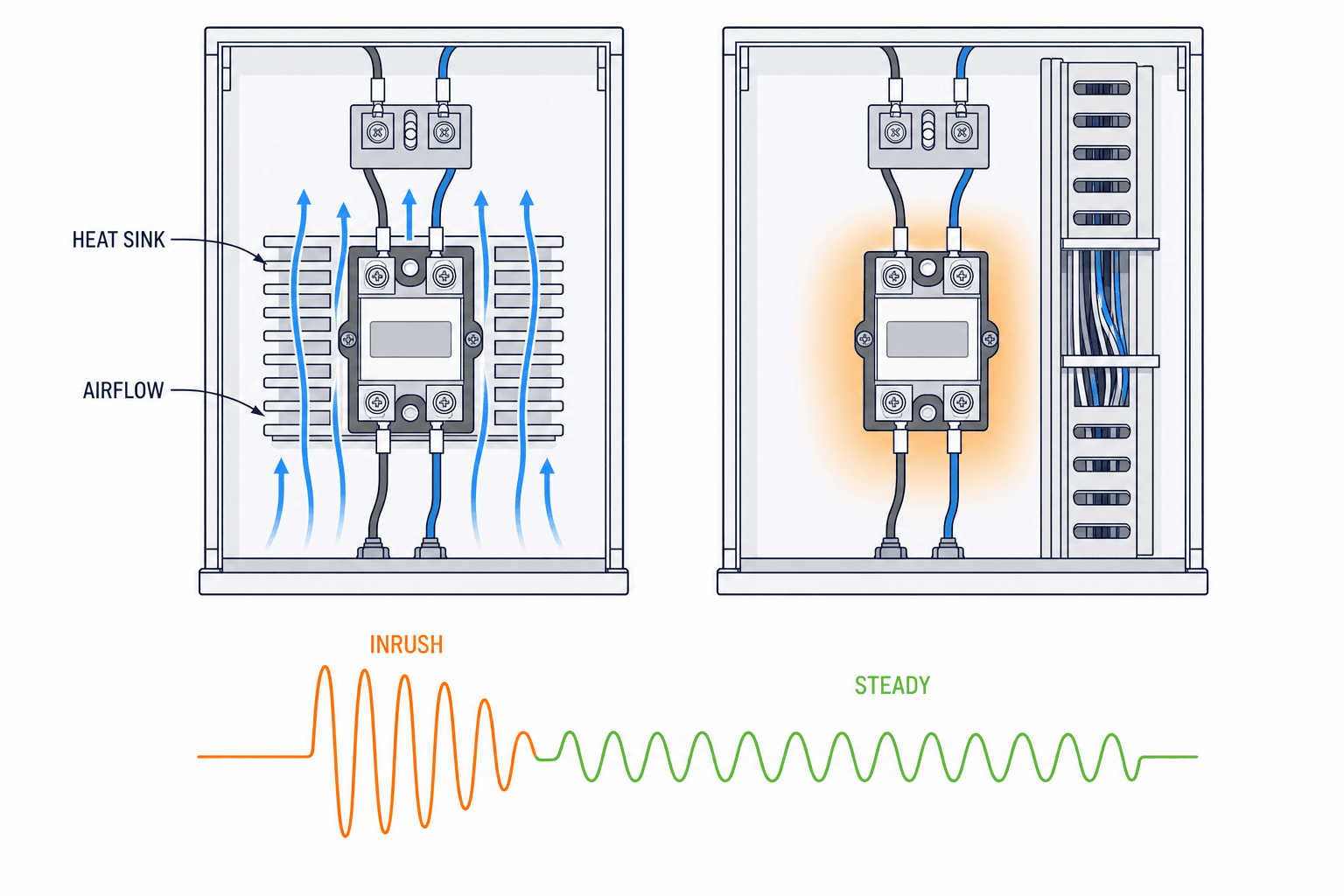
Cold and hot resistance can differ in a heater. Lamps, transformers, and coils can also draw a current at switch-on that the running rating does not describe. Gather the peak value, its duration, and how frequently it repeats. Separate first energization, normal cycling, load replacement, and fault cases. Compare load data with the candidate SSR’s curves on the same time basis. A headline “20 A” rating does not prove that a 20 A load can be switched continuously in a warm enclosure.
A non-repetitive surge rating is not a normal repeated switching allowance. OMRON treats the non-repetitive surge figure as a limit and discusses a transformer example with specific conditions. Do not export a coefficient from that example as a universal rule for another make or load. Ask the supplier to confirm the selected model against the measured peak, pulse length, switching frequency, and cabinet temperature. Record the answer as part of the selection calculation. OMRON technical guide.
Short-circuit protection is another question. Review the fuse or breaker specified for the chosen SSR, wiring size, and coordination with upstream protection. A panel main breaker alone should not be assumed to protect the semiconductor. Consider what the load does if the SSR remains conductive after a failure. A heater with a hazardous overtemperature condition may need independent overtemperature protection. The final safety design must follow the equipment risk assessment, applicable requirements, and manufacturer instructions. Panasonic safety notes; OMRON safety precautions.
5. Heat sinking and derating inside the cabinet
An on-state SSR dissipates power because its output has a voltage drop or on resistance. A catalog current rating may assume a particular heat sink, ambient temperature, mounting orientation, spacing, or airflow. Read the candidate’s current-versus-temperature curve and mounting instructions. Then verify continuous operation at the highest expected cabinet ambient temperature. Panasonic warns that operation near absolute maximum ratings under high load or temperature can lower reliability even if limits are not formally exceeded, and calls for derating and actual-condition evaluation. Panasonic usage cautions.
The difference can be material: OMRON’s G3NE-220T(L)(-2)-US specification lists a 0.1–20 A load-current range at 40°C with its specified heat sink or radiation plate, versus 0.1–5 A at 40°C without a heat sink. This is an example for that model and those stated conditions only, not an allowance for other SSRs or any particular Thai cabinet. The same specification notes that load current varies with ambient temperature. OMRON G3NE specifications.
For a thermal estimate, take power loss from the selected device’s datasheet and follow the heat path through junction, case, interface material, heat sink, and ambient air. celduc’s heat-sink white paper illustrates using load current and ambient temperature to choose thermal resistance; its examples belong to the stated products and assumptions. A lower K/W heat-sink value means less temperature rise for a given dissipation under the specified airflow, but the actual installed performance still needs checking. Do not copy a junction-temperature value or loss figure from one SSR into another manufacturer’s calculation. celduc heat-sink selection.
Poor contact between the SSR and heat sink defeats the purpose of the sink. Check the specified thermal grease or pad, torque, mounting surface, airflow direction, clearance to cable ducts, and heat from adjacent devices. OMRON explains interface materials for some products and cautions about mounting certain models directly to a panel. Follow the instructions of the chosen model. Include a fan-failure or air-conditioning outage state when relevant to the site. OMRON heat guidance; OMRON safety precautions.
A brief FAT with the cabinet door open in a cool workshop does not reproduce continuous operation at the installation site. Plan measurements at the high-duty production recipe with other heat-generating components energized. Log the SSR case, sink, and surrounding cabinet-air temperatures at defined points. Set acceptance limits from the selected datasheet before testing and record the probe location. Derating for a Thai factory should follow measured cabinet conditions, not an arbitrary country-based percentage.
6. Off-state leakage, minimum load, and isolation
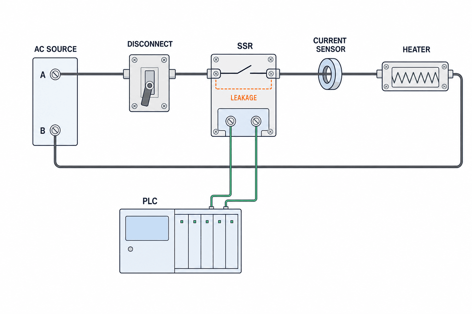
“OFF” on an SSR is not the same as an open mechanical air gap. Off-state leakage, sometimes influenced by a snubber, can faintly illuminate an LED lamp or affect a high-impedance input. OMRON illustrates this with a lamp and a bleeder resistor. Panasonic also notes that certain products have a minimum load current below which operation may be unreliable. Oversizing the SSR without checking the actual load can therefore create a different problem. OMRON leakage explanation; Panasonic usage cautions.
If a bleeder or dummy resistor is proposed, calculate its dissipation and temperature and verify the residual off voltage with the real load and wiring. Cable capacitance and load input impedance affect the reading. Never assume that an off command makes load terminals safe to touch. Use the specified disconnect, lockout, and absence-of-voltage check for maintenance; do not treat a normal load-switching SSR as an isolator. Confirm input-to-output insulation ratings and required clearances from the actual datasheet and system specification, rather than relying on a generic “opto-isolated” description. OMRON safety precautions.
Define fault detection, too. For a heater, comparing the command with a separate current or temperature measurement could reveal “off commanded but current present” and “on commanded but no current.” The coverage depends on the wiring and sensor location. List the faults that the system must detect and provide independent protection where a hazardous overtemperature could arise. Do not assume that every SSR failure produces an open circuit.
7. Put surge protection into the actual wiring drawing
The selection sheet is incomplete without a schematic showing input wiring, load wiring, fuse, protective devices, earth connection, and significant cable lengths. Panasonic describes input-side noise susceptibility, varistors for some AC output surge cases, and spike suppression for DC inductive loads. First establish which protection is already built into the chosen SSR. If external components are required, specify their ratings and locations for that exact model. An external snubber can also affect leakage or measured off-state voltage. Panasonic usage cautions.
In a real cabinet, routing between power and control cables, grounding, nearby contactors or solenoids, and supply disturbances influence operation. Confirm that the PLC output can drive the SSR input and that off-state leakage on the PLC side cannot create an unintended on state. Where one output drives several SSRs, check both per-point and common-terminal limits. A drawing labeled only “24 V” and “AC 220 V” is too thin to audit the combination.
If a contactor is used as well, distinguish its role from the SSR’s in the schematic. Our magnetic contactor selection guide discusses load duty, auxiliaries, and protection. Maintenance isolation requires a suitable disconnect or contact arrangement in series with the load current path, assessed as part of the complete circuit. Opening a contactor wired in parallel with an SSR would not interrupt current flowing through the SSR. State which device performs routine cycling, isolation, and fault response, then verify the design against the machine’s safety requirements.
8. A seven-point SSR comparison sheet
| Item | What engineering should state | What to verify for each candidate |
|---|---|---|
| Control input | PLC output type, voltage range, available current, polarity | SSR input range and thresholds |
| Load | AC/DC, voltage, frequency, phases, resistive/inductive | Output rating and permitted load type |
| Current | Running RMS, peak, duration, repetition | Load waveform and SSR surge curves |
| Turn-on | Zero-cross or random, control cycle | Load and controller compatibility |
| Thermal | Highest cabinet temperature, duty, mounting, spacing | Derating curve and heat sink |
| OFF state | Leakage limit, minimum load, residual voltage | Datasheet and real-load test |
| Protection | Surge, short circuit, independent thermal limit, maintenance isolation | Schematic and manufacturer requirements |
For example, “5 kW heater, 220 V” is not a complete current specification: single versus three phase, wiring arrangement, tolerance, and heater resistance all matter. Calculate from the actual circuit, add start-up evidence from the load maker or measurements, then request a supplier response including thermal suitability. A fixed “twice the amps” rule cannot replace the device curve and operating conditions.
9. RFP, FAT, and SAT checkpoints
RFP: send conditions, not only a preferred part number
Attach the load list, one-line and detailed schematics, PLC and controller output specifications, switching frequency, peak-current data, highest cabinet ambient, available heat-sink space, allowable off-state voltage, and spare-parts plan. Ask each bidder for a model number, application assumptions, heat-sink and protection requirements, derating evidence, lead time, and a defined alternative. If the model might be substituted locally, write equivalence requirements for input, output, thermal behavior, terminals, leakage, and protection—not merely mounting-hole dimensions.
FAT: test the completed cabinet
Check polarity and wiring, on/off operation at no load and normal load, start-up voltage/current waveform, temperature rise during sustained operation, residual load-terminal voltage when off, and fault detection. If a temperature controller drives the SSR, test the shortest planned control cycle. Specify acceptance values from the chosen device before the test. Do not create a deliberate short circuit without a documented test plan and manufacturer-approved method.
SAT: repeat under installed conditions
Measure again with the actual supply, load, ambient temperature, closed cabinet door, and operating fan or cooler. Reassess noise, surge, and off-state leakage if the on-site cable length or connected load differs from FAT. Hand over a maintenance process that requires disconnection and voltage verification rather than relying on an SSR indicator lamp. Record spare-part model, thermal interface material, torque, and cabinet photographs.
FAQ
How much current margin should I add when selecting an SSR?
No universal multiplier exists. Match running current, inrush peak and duration, switching frequency, cabinet temperature, and heat sink to the exact candidate’s curves. Do not treat a non-repetitive surge number as permission for routine repeated switching. OMRON guide.
Is zero-cross always right for a heater?
It is often a candidate for burst-controlled resistive heaters. Confirm the controller mode, start-up current, supply, and noise requirements. Phase-angle control may need a compatible random turn-on unit. Test inductive or phase-shifted loads on real equipment. Panasonic cautions.
Does switching an SSR off remove all voltage from the load?
No. Leakage, suppression components, and high load impedance can leave measurable voltage or faint illumination. Use an appropriate disconnect and verify absence of voltage before maintenance. OMRON leakage guide.
Can I ignore cabinet temperature if the SSR has a heat sink?
No. Heat-sink performance depends on ambient temperature, orientation, airflow, interface material, and neighboring devices. Check the product derating curve and actual temperatures. celduc thermal guide.
Can a standard SSR double as a safety stop or maintenance isolator?
Do not assume that. Leakage and possible conductive failure require a separately designed safety and isolation function according to the machine risk assessment and component instructions. OMRON safety precautions.
Conclusion
Select an SSR by separating control input from load output, then resolve AC/DC compatibility, switching method, steady and inrush current, thermal limits, off-state behavior, and circuit protection. Document the application assumptions and use the exact product datasheet plus FAT and SAT measurements to close the decision.
If you are still mapping the roles of an SSR, temperature controller, and contactor in a Thai factory panel, contact TOMAS TECH. A load list and cabinet conditions are enough to begin structuring the candidate comparison and test plan.


