


Selecting an industrial Ethernet media converter starts with the complete link, not a catalogue distance claim. Define the copper port, existing fiber plant, optical interface at both ends, control traffic and maintenance method. A link between a machine cabinet and a control room may fail its acceptance test even when the nominal distance looks comfortable: patch panels, connectors, cabinet temperature, power and fault signalling all matter. This guide takes an engineering and purchasing team from site survey through RFP, factory acceptance test (FAT) and site acceptance test (SAT).
Three decisions drive the project. Locate the actual copper-to-fiber boundary on a drawing. Choose single-mode (SM) or multimode (MM) fiber by checking the installed plant, paired transceivers and optical loss budget, not distance alone. Then reproduce a link failure and verify what the machine and monitoring system actually see. A media converter changes the transmission medium; it is neither a firewall nor a security boundary.
Where an industrial media converter belongs
A camera, PLC, instrument, HMI or edge computer may have a copper Ethernet port while the remote control room has a fiber backbone. A converter can preserve that endpoint while introducing a fiber segment. The Fiber Optic Association (FOA) design guide starts with the communication system, speed and route before selecting transmission equipment and cable. Apply the same sequence here.
A common arrangement is a short copper patch lead from the equipment to a converter, a fiber backbone, and a second converter or fiber-capable switch at the far end. Both ends must agree on speed, fiber type, wavelength, connector and transmit/receive arrangement. If only one end is being replaced, obtain the remote device specification, installed SFP model and patch-panel records first. Identical LC connectors do not establish optical compatibility.
Media conversion addresses physical connectivity and cabling constraints. Network zones, traffic policy, authentication and remote access require a separate design. See the NIST Guide to OT Security for the wider security context. If a one-way data flow is required, consult our separate industrial data diode selection guide.

Survey the factory fiber Ethernet link before requesting quotes
Create a link register before a product shortlist. For each circuit record source and destination, endpoint, copper port, traffic purpose, required speed, redundancy, route, fiber cores, patch panels, connection points and power supplies. Review the register with equipment, cabling and operations staff. It exposes mismatches such as a cabinet with room for a device but no safe bend path for its patch lead, or a UPS-backed control room paired with an unprotected machine cabinet.
Do not infer SM or MM solely from a drawing or cable jacket. Reconcile as-built documentation, termination labels and available test records. If spare cores will be reused, verify end-to-end identity, connector polish and polarity, and any intermediate joints. For a new run, specify spare capacity and working space for future replacement. The converter location affects copper length, optical route, power and maintenance access; fix the location on the drawing before finalizing the bill of materials.
| Survey item | Record | Likely consequence if omitted |
|---|---|---|
| Endpoint | Model, copper speed, negotiation and protocol | Link mode mismatch |
| Fiber plant | SM/MM, cores, route, joints, connectors and test results | No defensible optical budget |
| Cabinet and power | Temperature, mounting, supply range and backup | Device stops in service |
| Operation | LEDs, alarm contact, remote monitoring and spares | Slow fault isolation |
| Acceptance | FAT/SAT method and evidence | “Connected” means different things to each party |
Single-mode versus multimode: decide from the installed system
“SM for long links, MM for short links” is an incomplete procurement rule. The fiber types have different propagation characteristics and require the appropriate optics. FOA describes common MM use in premises networks and SM use for longer and outside-plant links, while emphasizing the relationship between the communication equipment and cable. If an existing backbone is available, identify it and select a compatible interface. For new construction, compare length, speed, future upgrades, optical module availability, patch-panel standardization and spare-part policy.
Never connect an SM transceiver to MM cable, or the reverse, on the basis of matching connectors. Connector type does not prove matching wavelength, transmit power, receiver sensitivity, maximum input or link method. With an SFP-based converter, specify the exact SFP model and check the remote SFP and host device. A single-fiber WDM/BiDi pair needs complementary transmit and receive wavelengths. A two-fiber pair needs verified transmit/receive polarity.
| Decision factor | SM case | MM case | Required evidence |
|---|---|---|---|
| Existing cable | Existing SM or a common outside-plant backbone | Existing MM worth retaining | Cable records and tests |
| Link performance | The selected optics meet speed and loss needs | The selected optics meet speed and loss needs | Both endpoint and SFP data sheets |
| Lifecycle | Provision for future reach or upgrades | Retain existing premises assets and spares | Expansion and maintenance plan |
This table is a selection framework, not a universal distance or price claim. Phoenix Contact’s media converter range illustrates that optical interfaces and functions vary by family. Confirm the exact ordered model separately from the family overview.
Calculate the SFP optical loss budget in both directions
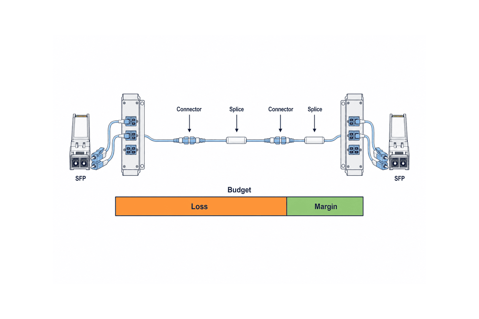
A stated maximum reach is only a screening aid. Obtain minimum transmitter output and receiver sensitivity to establish the available optical budget. Estimate fiber attenuation, connector and splice loss, patch leads, other path loss and a maintenance margin. Compare this total with the available budget for each direction separately. Also check that maximum transmitter output will not exceed the remote receiver’s maximum permitted input; a very short path is not automatically safe merely because its loss is low.
FOA lists cable-plant loss budget analysis as part of network design. The generic calculation is available loss budget = minimum transmitter output − receiver sensitivity; expected path loss = fiber + connectors + splices + other path loss. Expected loss plus the agreed margin must fit within the available budget. Use the actual SFP data sheets, cable design and acceptance method to set numerical values. Repeat for the reverse path and verify the maximum receiver input condition.
A short run with several cross-connects can have more connection risk than its length suggests. Conversely, a low-loss route does not fix a wavelength or optical-mode mismatch. Pair the design calculation with measured results when reusing installed fiber; the measurements become a baseline for future troubleshooting.
Specify environmental, power and diagnostic requirements
“Industrial” on a product label is not an acceptance criterion. Measure or specify cabinet temperature, condensation and dust exposure, vibration, electrical interference, mounting clearance, supply voltage and backup arrangement. The controlled communication room and a machine cabinet beside a heat source may need different device ratings. If redundant inputs are required, document the two independent power sources and test the loss of either input.
The Phoenix Contact MC 1000T-MM LC product page, Moxa IMC-P21GA-G2 page and Moxa selection guide are useful examples of model-specific features. Their ratings are not universal properties of industrial media converters. Base the purchase decision on the data sheet for the exact part number and revision offered.
List power, copper-link and optical-link LEDs separately from alarm contacts and remote management. An unmanaged converter may be simple to install yet provide no signal to a central system. For link-fault pass-through (LFPT), describe which failed segment changes which opposite port and how the link recovers. Phoenix Contact describes models with an LFPT switch and status LEDs in its range; verify the feature on the proposed part number.
Test LFPT against the control system, not only the converter
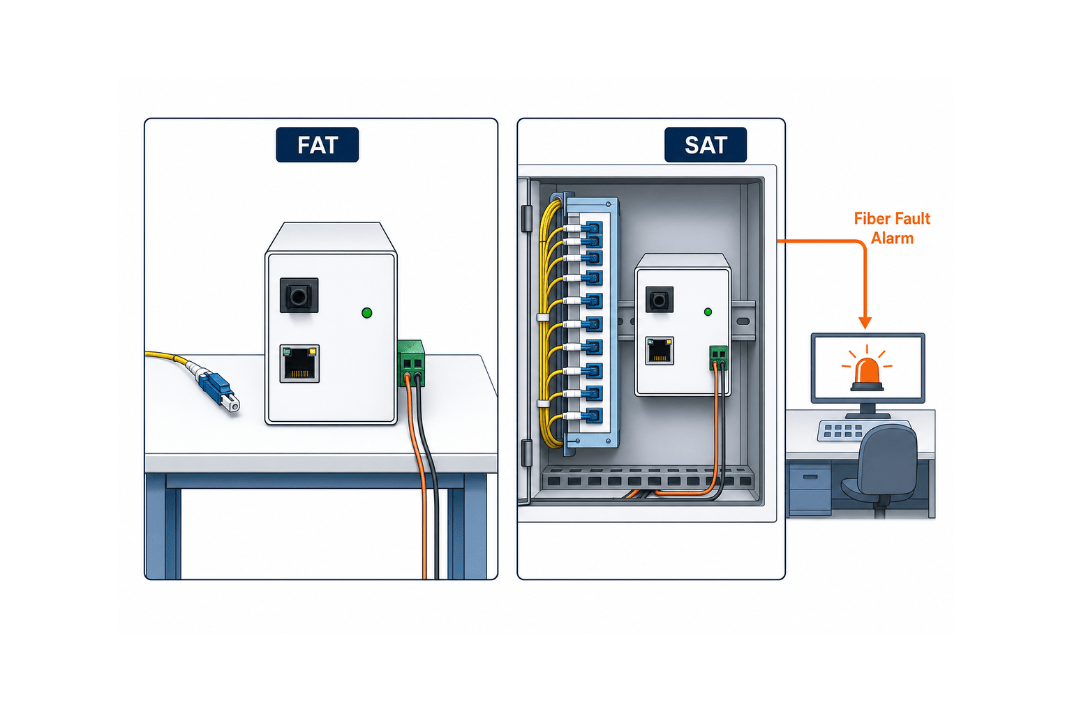
LFPT is intended to reveal a link failure at the other interface. It does not by itself guarantee a machine’s fail-safe behaviour or a redundant network switchover. Disconnect the fiber in a controlled test and record whether the copper port drops, what the connected switch reports, and how the monitoring system alarms. Production testing requires an approved procedure and safe window.
Repeat in the other direction by disconnecting the endpoint’s copper cable. Record the remote optical and switch states. A catalogue checkmark cannot establish bidirectional behaviour, power-loss behaviour or recovery time in your installation. Confirm the expected action in FAT with a representative setup, then repeat on the real path in SAT. Fault notification and restored application traffic deserve separate pass criteria.
Confirm control protocols, latency and time synchronization
Factory Ethernet can carry cyclic control, discovery, redundancy and time synchronization in addition to ordinary TCP/IP. The word “transparent” does not prove the relevant frame handling, latency or fault recovery for every converter and operating mode. Phoenix Contact describes store-and-forward and cut-through modes and applications involving time-sensitive industrial protocols. Ask the equipment manufacturer to approve the specific topology and test the real protocol.
If PTP or another time source is involved, a link-up LED alone cannot prove timing performance. Define time accuracy, network-device behaviour, load, and recovery after a fault as separate tests. Our factory PTP time synchronization guide covers the wider timing design. In this RFP, identify the protocol and the acceptance method needed for the converter link.
Compare the complete delivered link, not the converter price
A low unit price may exclude SFPs, supplies, DIN-rail accessories, patch cords, termination, test work and spares. For an SFP model, check module part number, host support, supply continuity and firmware combination. A fixed optical port can simplify a standard link but may constrain future optical changes. Compare replacement units and stock policy as well as the purchase price.
For a Thai plant, include local availability, replacement lead time, support language and site delivery in the operating plan. Decide which converter, SFP and supply will be stocked, and label approved replacements. A tested compatibility list is more reliable than an assumption that superficially similar modules are interchangeable.
Put measurable requirements in the RFP
A request for “one industrial media converter set” is too vague. Provide a row for each link and require every bidder to return the same evidence. Mark each requirement mandatory, acceptable with an alternative, or informational. An unanswered cell must not be treated as compliance.
| RFP field | Example of required submission |
|---|---|
| Service | Machine A to control room B; primary/backup and traffic type |
| Copper | Port speed, connector, negotiation and peer model |
| Optical | SM/MM, core count, wavelength, connector, SFP/fixed port and peer model |
| Budget | Loss calculation both ways, maximum receiver input, site measurement and margin |
| Environment | Cabinet temperature, supply, redundancy, dimensions and applicable approvals |
| Behaviour | Protocol, LFPT, alarms, monitoring and recovery |
| Deliverables | Exact data sheets, wiring, settings, FAT/SAT records and spare list |
Define “equivalent” by optical compatibility, protocol, environment, support and approval, not a single word in the purchase order. Ask suppliers to disclose exceptions and cite the exact page of supporting documentation. A technical comparison table with requirement, proposed value, evidence, FAT check and SAT check can become the acceptance checklist.
Rules for a meaningful comparison matrix
Do not copy only catalogue maxima into the bid comparison. Stated reach depends on the optical module, fiber and loss assumptions; environmental limits can depend on power and mounting. Give every row columns for required value, proposed value, exact document page, FAT check and SAT check. For a deviation, record the proposed alternative, added component, test and remaining risk.
“Enough optical budget” is reviewable only when minimum transmit power, receiver sensitivity, plant loss, margin and the return direction are shown. “Suitable temperature” needs the expected cabinet temperature beside the exact model’s rating. “Remote monitoring” needs the actual signal, failure type and receiving system. Build the matrix at a level that can be reused as a test sheet.
FAT: prove the equipment combination before shipment
Use the proposed converter, SFP, supplies and peer switch wherever possible. Record model and firmware, connect according to the drawing and test the planned speed and application traffic. Include one power-feed failure, copper disconnect, fiber disconnect and recovery. A successful ping is insufficient for control protocol acceptance. If the actual PLC or application cannot be present, identify the FAT simulator and explicitly defer the remaining test to SAT.
Write expected LFPT effects as a sequence: failed side, opposite LED, monitor alarm and recovery. Treat a PTP accuracy test separately if timing matters. FAT reduces equipment-combination risk; it cannot certify the finished long fiber plant. Keep that distinction in the test report.
SAT: accept measured fiber and real recovery
After installation, inspect and clean connectors, verify core identity and polarity, and measure loss on the installed route. The FOA fiber testing quickstart explains the importance of suitable instruments, method and records. Agree on wavelengths, reference method, direction, instrument and pass limits before testing. Record measurements against the link ID and test in both directions when the design or contract requires it. Receiver optical power alone is not a substitute for the contracted cable-plant test.
Inspect cabinet temperature and power, cable protection, labels, connector clearance and patch-lead bend. Demonstrate fiber, copper and power-failure alarms on the actual monitoring display and execute the agreed restoration procedure. Schedule fault injection with production and safety personnel so the test does not create an uncontrolled process event.
Keep a usable link register after handover
Update the register to its as-built state: cabinet and port IDs, converter and SFP part numbers, fiber cores, patch-panel ports, loss measurements, test date, margin and spare location. Make alarm names match physical locations. Record configuration needed after a replacement. As more lines are added, distinguish a standard approved combination from tested exceptions.
A fault checklist should separate power, copper link and optical link before moving to patch cords, connector condition, receive level and recent work. Do not unplug a live optical circuit without a permit and protection procedure. After replacement, verify application traffic, alarm clearance and any relevant synchronization or redundancy—not merely a green LED.
Four boundary conditions that often change the decision
Placement. The shortest fiber route may place the converter where power, enclosure protection or access is poor. A unit beside the endpoint reduces copper length but needs a local supply and working space. Fix the serviceable location first and recalculate both cable runs.
The far end. Two converters can be qualified as a pair; a converter facing an installed fiber switch must satisfy that switch’s SFP support and port settings. Check speed, duplex, negotiation, firmware and fixed optical-port settings in a representative test.
Redundancy. Two fibers in one duct, patch panel and power supply share failure modes. Specify diverse paths and power where required, the network switchover mechanism, application reconnection and the alarms operators will see. Test on a simulator before injecting failure into production.
Security. Fiber can help with electrical interference, but it does not filter Ethernet traffic. Define network zones, access rules, maintenance connections and logs separately from media conversion. Clarify whether a reference to “secure fiber” means electrical properties or cybersecurity controls.
Manage substitutions and spare parts
A substitute SFP needs more than the same speed and connector. Compare wavelength, output, sensitivity, maximum input, temperature and peer operation, then decide which acceptance tests to repeat. Log the old and new part numbers. Separate emergency restoration from approval of a permanent standard configuration.
Set spare quantities using downtime impact, local lead time, number of shared links, tested compatibility and storage conditions. Similar SM and MM modules can easily be confused, so label stocks by approved application. Record failed-part symptoms, replacement serial numbers and recovery time; that evidence helps diagnose intermittent faults.
Final checks before issuing the purchase order
Match each line in the link register against the bill of materials. Confirm that converters, optics, supplies, mounts, patch cords, cleaning items and test services are included. Similar part numbers may hide different fiber types, connectors or temperature ratings. State how substitute parts must be reapproved so the delivered combination matches the FAT configuration.
Assign responsibility for cabinet power, fiber termination, switch configuration, production shutdown, witness testing and alarm registration. Agree on proof of completion: labelled patch-panel ports and measurement records for the fiber, and configured alarm names and destinations for monitoring. Freeze the versions of the RFP, drawing, parts list and test sheet. If a change is proposed, recheck optical budget, peer compatibility and affected FAT/SAT tests; record the approval and rollback conditions.
Frequently asked questions
What distinguishes an industrial converter from an office model?
“Industrial” is a product category, not a substitute for site acceptance criteria. Compare exact model ratings for temperature, power, mounting, vibration, alarms and support against each cabinet.
Should a factory fiber Ethernet link use single-mode or multimode?
Identify the installed fiber and both endpoint optics first. For a new run, compare speed, upgrades, modules and maintenance as well as length. Confirm compatibility and a two-way optical budget for the ordered parts.
How is an SFP optical loss budget calculated?
Subtract receiver sensitivity from minimum transmitter output to find the available budget. Subtract the planned fiber, joint and connector loss and reserve a margin. Check the reverse path and maximum receiver input too. Use actual SFP specifications.
Can a media converter replace a firewall or data diode?
No. It converts the physical medium but does not enforce traffic permissions or one-way flow. Design security boundaries separately.
What belongs in RFP, FAT and SAT?
Use the RFP to define requirements and pass methods, FAT to test equipment and fault behaviour, and SAT to accept the installed fiber, monitoring and recovery. Carry part numbers, configuration and exceptions between stages.
Conclusion
Select the industrial media converter as part of a complete link. Capture SM/MM, paired optics, optical budget in both directions, site environment, LFPT, monitoring and protocol behaviour in one link register. Freeze measurable requirements in the RFP; prove the equipment combination in FAT and the installation and operating procedure in SAT.
Even during preliminary planning, existing cable drawings and endpoint details are enough to start a selection checklist. You can discuss a factory fiber connection with TOMAS TECH through our contact page.


