



Selecting a 24V DC power supply for a control panel by adding nameplate load currents can miss startup voltage dips and a fault on one branch that stops the PLC. This guide for new and upgraded machines in Thailand connects the load schedule to capacity, cabinet temperature, voltage drop, redundancy, branch protection and FAT/SAT. Numerical examples illustrate a method; they are not universal ratings or substitutes for the selected products’ specifications.
Start with the loads that must keep running
A 24V system may supply the PLC, remote I/O, HMI, network equipment, sensors, solenoid valves and relays. If all loads share one supply and an unprotected distribution point, a valve-cable short can pull down the voltage available to the controller. Before choosing a wattage, identify the circuits that must retain status during a machine stop, those that should de-energize, and those that must be isolated when faulty. Production continuity, functional safety and maintenance recovery require separate decisions.
A PLC and network switch might need to continue recording a fault while a failed valve branch disconnects. The HMI may need power to show an alarm, but keeping its screen on is not the same as meeting an emergency-stop safety function. Define safety-related behavior through the machine risk assessment, applicable requirements and device instructions. A 24V system still needs suitable protection, bonding, wiring and documentation. IEC 60204-1 covers machinery electrical equipment and addresses overcurrent and control-circuit protection [1].
Draw a one-line diagram showing the AC input, power supply, DC distribution, protective devices, load groups and diagnostic signals. A technician should be able to identify where to measure first when a fault occurs. A purchase specification should say more than “24V, 20A”: record the boundary between critical and noncritical loads, where alarms go, and how each branch is restored.
Size the switched-mode power supply from a load schedule
Record continuous, startup and intermittent demands separately
For each device, record its model, input-voltage range, continuous current, startup current and duration, simultaneous-operation conditions, location, cable route, shutdown tolerance and planned expansion. A datasheet maximum and a typical measured current mean different things. Adding only normal readings risks undersizing; summing every independent worst-case rating can oversize the system. Confirm which loads can start together and which starts can be sequenced by the controller.
OMRON describes the basic output-capacity relation—voltage times load current—but also warns that temperature and load inrush can prevent output from rising even when continuous consumption is below the rated capacity [2]. Capacitors and internal DC-DC converters in PLCs and HMIs can produce behavior that a steady-current sum cannot explain. OMRON recommends comparing load startup behavior with the supply’s overcurrent characteristic [3]. Do not approve a design based on “continuous total below nameplate” alone.
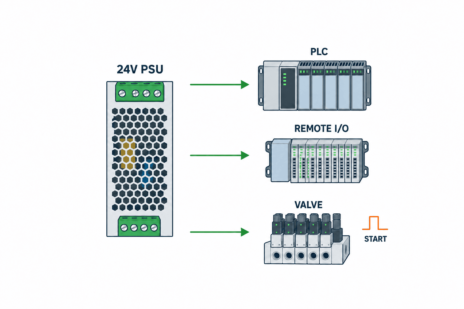
This is an illustrative calculation, not measured equipment data. Replace it with the chosen devices’ datasheets and commissioning measurements.
| Illustrative load | Example continuous current | Check at startup | Duty |
|---|---|---|---|
| PLC and I/O | 2.0 A | Initial demand and voltage-rise requirement | Continuous |
| HMI | 1.0 A | Boot current and allowed input voltage | Continuous |
| Network equipment | 0.8 A | Whether attached ports supply other devices | Continuous |
| Sensors | 1.2 A | Planned device count and simultaneous energization | Continuous |
| Solenoid valves | 3.0 A | Number energized together and surge treatment | Intermittent |
| Other/planned devices | 1.0 A | Confidence in expansion forecast | Conditional |
The example totals 9.0 A continuously, but it does not prove that a 10 A supply is adequate. Compare maximum simultaneous demand, the startup waveform, temperature-dependent usable rating, change allowance, protection behavior and voltage at the cable end. If a designer assumes a 20% planning allowance, the initial comparison becomes 9.0 × 1.2 = 10.8 A. Twenty percent is an illustrative assumption, not a universal code requirement. A supply can still enter current limiting during startup even if the continuous calculation includes an allowance.
Separate peak current from peak duration
Short-time overload features serve different purposes: a sustained boost, a boost lasting seconds, or a very short high current intended to operate a protective device. One particular Phoenix Contact 24V/20A model lists 25 A static boost, 30 A dynamic boost for 5 seconds and 120 A selective fuse breaking current for 15 ms [4]. These are model-specific specifications, not capabilities of all 24V supplies. Obtain the load’s peak magnitude, duration and repetition rate, then compare them with the candidate’s curves.
One very large PSU is not automatically the most reliable choice. Extra capacity does not identify a failed branch; two supplies do not remove a common AC input or common terminal failure. Compare capacity, selective protection and redundancy as different line items so that suppliers can explain their price and operating assumptions.
Cabinet temperature and mounting conditions in Thailand
The relevant ambient temperature is the air surrounding the installed PSU, not the temperature in a weather report. The top of a closed cabinet, a position beside a drive or contactor, and restricted ventilation can make it much warmer than the room. Datasheets specify derating by ambient temperature, mounting orientation, clearances and sometimes altitude. The particular Phoenix Contact product cited above specifies 2.5% per kelvin derating above 60°C [4]. Do not apply this figure to another model; apply that model’s own curve to the actual installation.
Avoid blocking the supply’s air path with a cable duct and check nearby heat sources. Two devices labelled 24V/10A may offer different usable continuous currents after mounting conditions are considered. Predict cabinet temperature during design, then measure it at FAT with heat sources energized and at SAT with the installed cabinet closed. See our related guide to control-panel thermal design and cooling.
For a Thai factory, add serviceability to the electrical criteria: exact replacement part number, input range, terminals, mounting dimensions, alarms, local availability and substitution approval. There is no single ambient-temperature assumption that applies to every Thai installation. Define conditions from the actual cabinet, room, air-conditioning outage scenario and duty cycle. Check conformity documents and required approvals against the equipment and customer requirements.
Judge 24V voltage drop at the load terminals
24V at the PSU terminals does not guarantee 24V at a remote sensor or I/O module. Include the outgoing and return conductors, cross-section, contact resistance, protection module, redundancy module and actual load current in the calculation and measurement. When valves energize together, use a measurement method that can capture a short dip. Derive allowable voltage from each load’s specification, rather than inventing a generic tolerance for “24V equipment.”
As a first approximation, voltage drop = current × total circuit resistance. Resistance depends on material, size, temperature and real route length; contacts and modules add further drops. With hypothetical 0.3 ohm round-trip resistance and 2 A, the wire alone drops 0.6V. This is not a permitted voltage-drop limit. Compare both near and far devices with their input ranges under changing loads; raising the PSU setpoint may overvoltage a nearby device.
For long field runs, a bigger central supply is not the only option. Properly protected, local power near the load can shorten cables. Phoenix Contact explicitly cites less cable length and voltage drop as benefits of an IP67 field PSU [5]. Decentralization brings its own enclosure, maintenance, AC distribution and protection questions. Our remote I/O selection guide helps map the communication and power routes together.
Design protection around the branch that should disconnect
Internal PSU protection is different from branch selectivity
A PSU’s internal overcurrent function protects the supply; it does not guarantee that only the faulty 24V feeder will turn off. If the whole supply current-limits, the PLC and HMI can lose voltage. Siemens explains that ordinary miniature breakers may not trip rapidly with a switched-mode supply because output current limiting and cable resistance reduce the fault current, potentially bringing the PLC to a stop [6]. The presence of breakers or fuses alone does not establish selectivity.
For electronic branch protection, compare each channel’s setting, startup allowance, shutdown curve, reset method, diagnostics, total PSU capacity and line resistance. Siemens describes selectivity modules that isolate a faulty feeder while maintaining other feeders [7]. Validate the specific PSU, protector, cable and load combination by manufacturer information and appropriate testing. Route channel diagnostics to the PLC and show the branch name on the HMI to shorten fault finding.

Group feeders according to how the plant will maintain them. Separate PLC/network, HMI, sensors and valves when their fault response differs. Too many branches add components, space, wiring and spare-parts work. Set the number of channels from acceptable fault extent, not merely device count. Check each cable’s current rating against its channel setting.
Keep AC input, DC branch and load-side protection distinct
AC upstream protection concerns the supply input and its feeder. DC branch protection limits the effect of load-side faults. Load-side surge or polarity measures respond to device behavior. For valve and relay coils, follow the load manufacturer’s surge-control instructions. Input inrush on energizing the PSU is different from output demand when loads start; do not combine them into one design figure. Use the exact manufacturer’s input breaker recommendation for the selected model.
Write an acceptance criterion such as “the simulated valve-feeder fault isolates that feeder while PLC logging and communications continue.” Fault simulation requires an agreed safe test method, isolation and qualified personnel. Do not create a fault by directly shorting live terminals. At FAT use an appropriate test fixture or manufacturer-provided function and record the alarm and reset behavior.
Design 24V redundancy for a named failure mode
Two units side by side are not enough
If a single PSU failure must not remove a critical load, separate the paths, use a suitable redundancy/decoupling arrangement, and make sure either surviving supply can serve the critical demand. Siemens describes redundant modules that decouple two supplies so a healthy unit takes over after one fails [8]. Shared upstream breakers, terminals, ducts and hot spots can remain common failure points. State which single failure the design must tolerate.
In a 1+1 design, each path can support the entire critical load. Two supplies whose combined output is only just sufficient may leave the system undersized after one stops. For a hypothetical critical load of 8 A, verify at least 8 A usable continuous output from each remaining path under its real ambient conditions, including redundancy-module rating and voltage drop. Also specify loss-of-unit alarms. Parallel connection must follow the product maker’s permitted models and wiring; OMRON warns that unsupported parallel operation can produce unbalanced current [9].
Redundancy is not the same as uninterruptible operation. Two PSUs fed by one AC bus can tolerate one PSU failing but not loss of that AC bus. For supply dips or outages, separately determine the required hold-up, DC UPS or buffer arrangement, and load duration. Batteries add inspection, replacement and alarm duties. Derive hold-up time from the machine shutdown and data-saving sequence, not a generic number taken from an article.
Document a decision not to add redundancy
For a small machine that can stop safely and restart quickly, a single supply with a stocked spare, documented replacement procedure and selective branch protection may be reasonable. Compare upfront cost with stop loss, repair time, local availability, cabinet space and inspection effort. If redundancy is declined, state that a PSU failure stops all loads, how quickly replacement is expected, and where the spare is kept. Clear expectations avoid disputes after a breakdown.
Write a comparable procurement specification
“One 24V DC supply” produces proposals that cannot be compared. Give bidders the load schedule, AC source, input range, continuous and startup demand, cabinet temperature and mounting conditions, field-cable lengths, branch protection, redundancy/outage objectives, alarm interface, replacement requirements and FAT/SAT criteria. Request the one-line diagram, terminals schedule, protection settings and thermal assumptions as deliverables.
| Comparison point | Question for bidder | Evidence at approval |
|---|---|---|
| Capacity | Can it supply maximum simultaneous load at installed temperature? | Datasheet and calculation |
| Startup | Will simultaneous starts trigger current limiting? | Waveform and test plan |
| Branch protection | Does one feeder fault leave the PLC running? | Coordination evidence and FAT record |
| Redundancy | Does a single unit failure leave critical loads running? | One-line diagram and one-side-off test |
| Voltage drop | Is the farthest input inside its allowed range? | Cable calculation and SAT readings |
| Heat and service | Is the closed cabinet within rating, with replaceable parts? | Thermal study and bill of materials |
Require the full part number: terminal style, input phase, features and thermal rating can vary within a family. Compare total architecture costs, including cooling and branch protection. If PSU and protector come from different vendors, verify the electrical combination rather than transferring a same-vendor example without evidence.
On retrofits, existing 24V loads may not appear on the drawings. Before quotation, measure run, stop and start currents, available headroom, spare terminals, loaded voltage and cabinet temperature. Separate equipment that remains from equipment to be removed. Where documentation is incomplete, state that final capacity and settings follow a site survey. Otherwise a previously undocumented valve bank or new terminal can affect cost and schedule after award.
Prove the selection at FAT and SAT
FAT checks the panel and machine before shipment; SAT verifies the installed cables and actual loads. At FAT inspect drawing conformity, polarity, terminal numbers, PSU setting, channel settings, alarms and a safe one-side-off redundancy test where applicable. At SAT include long field cables, real loads, closed-cabinet temperature, simultaneous operation and communication of faults to supervisory systems. FAT alone cannot establish voltage at the installed remote load.

| Test situation | Measurement or action | Basis for acceptance |
|---|---|---|
| Initial energization | AC input, PSU output and PLC input | Each device’s allowed input range and startup sequence |
| Maximum operation | Output, farthest load, current and cabinet temperature | Load specifications and temperature-adjusted PSU rating |
| Simulated branch fault | Faulted and healthy feeders, alarm | Only the intended feeder disconnects; critical load operates |
| One-side-off test | Remove PSU A or B by safe procedure | Critical load remains and fault indication arrives |
| AC dip/outage if required | Hold-up and controlled stopping | Machine-specific hold-up and safe-stop requirement |
| Recovery | Reset protection and restore supply | Agreed procedure, authority and restart order |
Set numeric acceptance values from selected devices and the machine specification. Record point, instrument, load state, time, temperature and allowed range—not merely “24V observed.” A normal handheld meter may miss a brief startup dip; choose recording or waveform capture as needed and align with PLC event times. Comparing PSU and far-end readings under the same condition helps separate source problems from cable problems.
Plan retesting after expansion. Added cameras, network devices, I/O or valves change current, startup behavior, temperature and voltage drop. Update the load schedule and protection settings, then repeat the affected tests. A design allowance is not permission for unlimited later additions.
Common failure patterns and review questions
Sizing from continuous current only: A PLC that restarts only at switch-on points toward simultaneous startup and overcurrent behavior. OMRON identifies cases where startup current operates protection despite a normal steady-state current [10]. Consider sequencing or separating loads as well as supply capacity.
Accepting only the PSU-terminal voltage: Measure the remote device during the maximum load state. Check both the far device’s lower limit and a near device’s upper limit before adjusting output upward.
Calling two PSUs redundant without proof: Shared AC, common terminals or inadequate surviving-path capacity limit resilience. Use a one-side-off test and prove the alarm reaches maintenance.
Assuming any fuse gives selectivity: Current limiting, wire resistance and breaker curves determine what actually trips. Check the specific combination and tailor channel settings to cable and load.
Using room temperature for the cabinet: Test with the door closed and major heat sources energized. Account for the actual cooling, filters and operating condition.
Stopping at FAT: Record field-cable and real-load results at SAT and retain the points for future diagnosis.
At review, ask: What is maximum simultaneous current? Which loads start together? What is actual cabinet temperature? Does one feeder fault stop the PLC? What survives a PSU failure? What is the far-end voltage? Can the spare be sourced locally? Without these answers, two bids are not yet comparable.
A practical retrofit sequence
An existing panel can have live loads that its drawings omit. Trace each PSU, terminal, protective device and outgoing cable, and compare photographs with the one-line diagram. Identify the destination and current device for every field terminal, along with spare and abandoned wires. Ask maintenance about normal runs, starts, changeovers, cleaning and fault recovery; the appearance of the terminal strip does not reveal simultaneous use.
Measure existing current and voltage using an authorized safe procedure. If peaks matter, use an instrument capable of capturing them and record the machine state. A small measured current is not proof of long-term margin: the supply’s mounting, temperature, terminals and ageing still matter. Compare the installed orientation and free space with its datasheet.
Before transferring loads, verify the new PSU’s startup, output setting, polarity, bonding, terminal tightening and protection settings. Agree on the outage window and switchover order. Afterward verify PLC records, HMI, communications and distant devices. Keep a fallback and spare-part plan. Update the revision-controlled drawing, part numbers, settings, measurements, owner and date.
Two terminal strips labelled “PLC” and “field loads” may still return to one PSU. Conversely, two units may have outputs accidentally tied together even though parallel operation is unsupported. Trace the actual wiring and compare it with the product instructions; labels alone are not evidence of electrical separation.
Inspection, change control and design rationale
Keep the load schedule usable after handover. Every added sensor or network device should add its current, startup behavior, location, feeder protection and cable length. Empty terminals are not the same as electrical headroom. Change control should revisit far-end voltage, cabinet heat and the usable supply rating. Compare future measurements at the same terminals and machine state; otherwise differences are hard to interpret. Check ventilation paths, dust, fans, filters and whether diagnostic contacts actually report to the PLC and the maintenance team.
A spare labelled “24V, same amperage” may differ in input range, footprint, terminal type, thermal behavior, approvals, parallel-use rule and alarm contact. Qualify substitutions, revise the drawing and test procedure, and define safe isolation, residual-energy checks, polarity verification and restart order. A replacement should not depend on somebody remembering where the old wires went.
Document why capacity and channel settings were chosen: which operating mode defines maximum demand, which loads start together, what cabinet temperature was assumed, which terminal is farthest, and what must survive a failure. Briefly record why alternative proposals were rejected. For example, a larger single PSU may add startup margin without isolating a branch fault; dual PSUs may tolerate one failed unit without covering a shared AC outage. Keep protection evidence and FAT/SAT readings under the same revision control as the drawings.
When changing one of the PSU, protector or load, review the other two. Increasing PSU capacity can change available fault current. A new load affects cable drop and heat. Changing a protection setting alters the boundary between a failed branch and healthy branches. This linked check preserves the original design intent through small later modifications.
FAQ: 24V DC power supply selection
What current rating should a control-panel 24V DC PSU have?
Begin with maximum simultaneous demand. Compare peak startup current and duration, temperature- and orientation-adjusted rating, future changes and the protective-device combination. No fixed multiplier guarantees a correct result. The 9.0 A and 20% values above are illustrative, not standards. Confirm the chosen datasheet and FAT behavior.
Is a larger switched-mode PSU always safer?
It can provide continuous or startup margin, but it does not automatically isolate a feeder fault or ride through a power outage. Compare heat, footprint, cost and upstream protection as part of the complete architecture.
How are redundancy and a UPS different?
Redundancy typically supplies two paths for a single PSU failure. A DC UPS or buffer supports the load during AC loss or dips for a defined time. Both may be needed. Check common AC paths and downstream single points of failure, and derive hold-up time from the shutdown sequence.
Is an ordinary miniature breaker enough for 24V branch protection?
Not always. A current-limited PSU and line resistance can keep fault current too low for rapid breaker operation, dropping the common bus. Verify manufacturer coordination information and consider electronic selectivity modules; prove the intended fault isolation at FAT [6][7].
What should FAT and SAT measure for a 24V system?
Both should establish PSU and critical-load input voltage, current at maximum operation, protection and alarm behavior. FAT checks panel construction and settings; SAT adds actual cable length, connected load and closed-cabinet temperature. Choose acceptance values from the machine specification and installed products.
Conclusion
Control-panel 24V DC power selection starts with the loads that must continue operating. Size for continuous and startup behavior, apply the actual cabinet-temperature rating, verify voltage at the remote terminal, and ensure a faulty branch can disconnect without unnecessarily stopping critical controls. Treat redundancy and outage ride-through as separate requirements. Tie the decisions to one load schedule, one-line diagram and recorded FAT/SAT acceptance results so procurement and maintenance can use the same evidence.
If you are designing a new cabinet in Thailand, replacing an existing 24V supply or investigating startup trips after expansion, you can contact TOMAS TECH while the load schedule is still being assembled. We can begin with the measurement points, loads that must stay on and local procurement constraints.
Sources
- IEC 60204-1:2016+A1:2021, IEC, scope and amendments; this article does not replace the standard.
- Overview of Power Supplies, OMRON.
- Further Information of Power Supplies, OMRON.
- QUINT4-PS/3AC/24DC/20/KONF1, Phoenix Contact, model-specific characteristics.
- IP67 power supply, Phoenix Contact.
- SITOP selectivity technical document, Siemens.
- SITOP SEL1600, Siemens.
- SITOP add-on modules, Siemens.
- OMRON FAQ02011, OMRON.
- OMRON FAQ01877, OMRON.


