



A Thai injection molding plant may want cavity pressure monitoring yet struggle to decide which molds to instrument, how many sensors each needs, which readings constitute a reject, and how to link the results to existing presses and MES. Comparing product catalogs first will not settle those questions. Start with the quality defect to detect, the specific shot and cavity to identify, and the physical action that must follow an alarm. This implementation guide covers the initial survey, direct and indirect sensing, curve interpretation, mold retrofit, part segregation, and FAT and SAT requirements.
Define the purchase scope as measure, decide, segregate and trace
Injection or hydraulic pressure recorded by a press describes the machine side. Cavity pressure describes the pressure experienced by plastic inside the mold. The two are related but are not identical. Flow path, gate, viscosity, temperature and position in the tool all matter; identical machine setpoints do not guarantee identical conditions at the part. RJG describes near-gate sensing for packing and gate-seal assessment, and end-of-fill or critical-area sensing for filling and quality characteristics. An RFQ that simply says “record cavity pressure” gives suppliers no common basis for sensor placement or decision logic. RJG: Cavity Pressure Data
Specify four linked actions. Measure: name the tool, cavity, sensing position and acquisition conditions. Decide: compare the waveform and chosen features with limits established from approved processing conditions. Segregate: say whether the whole shot is rejected or whether individual cavities can physically be diverted. Trace: associate shot ID, cavity ID, tool, press, material lot and recipe revision. Only then does the measurement become a practical quality disposition.
Our earlier guide to an injection molding production management system deals with the larger genealogy connecting orders, machines, tools, materials, recipes and quantities. This article concentrates on the pressure change inside the mold during one shot and its use in quality decisions. The traceability cost and implementation guide helps separate sensor acquisition from lot-level genealogy.
Choose the defect before choosing the sensor
Cavity pressure is not a universal good/bad label. To stop short shots, look near the last region reached by melt or the critical region where the defect appears. To assess packing, gate seal or a dimension affected by hold pressure, the curve near the gate may be more useful. If one cavity of a multi-cavity tool behaves differently, a single representative curve may not support cavity-level isolation. RJG recommends placing a sensor according to the problem, and explains that an end-of-fill location is often useful for detecting short shots. RJG: Sensor Tips and Placement
Before a pilot, production engineering and quality should put defect photos, affected cavity, occurrence conditions, inspection method, escape impact and current containment unit on one page. Separate properties likely to correlate with pressure from those that still require dimensional or visual inspection. Low peak pressure may show a process change; it does not, by itself, certify every dimension. The project needs a study linking pressure indicators to measured part quality for the actual product, resin and tool.
Pick a pilot tool with a measurable defect and loss, a way to associate inspected samples with shots, available drawings and maintenance history, and the ability to hold processing conditions reasonably stable. If resin lot, regrind fraction, dryer settings and mold temperature all change during a short trial, it becomes hard to separate monitoring performance from process variation. Prove a narrowly defined use case, then decide how to extend it.
Near-gate and end-of-fill positions answer different questions
A post-gate sensor is well positioned to observe how packing pressure develops and holds after melt enters the cavity. An end-of-fill sensor addresses whether melt arrived at the far region and whether pressure propagated there. A critical rib, thin wall or appearance zone may require its own position. The best position depends on flow, gate design, resin, cooling and the quality property of interest; a catalog drawing cannot determine every tool’s layout. RJG: Five Questions Before Instrumenting a Mold
“End of fill” is not necessarily the point farthest away on the drawing. With a running tool, use controlled short-shot studies to see the actual fill pattern. Before a tool is built, use flow simulation and gate-layout hypotheses. Hot runners, multiple gates and valve gates can change branch balance, so one representative cavity may fail to cover all cavities. RJG discusses adjusting transducer count to flow pattern and runner configuration. State explicitly which defects and cavities each proposed sensor cannot observe. RJG: Sensor Tips and Placement
Placement also depends on allowable witness marks, clearance from ejector pins and cooling channels, mold thickness, connector access, and the ability to clean and replace a sensor. On an existing tool, the theoretically best position and a safe machining position can differ. Record the compromise, its expected impact on detection and any compensating inspection. Confirm it with real part and waveform studies before production acceptance. Avoid machining that creates an unjustified cooling leak or tool-life risk.
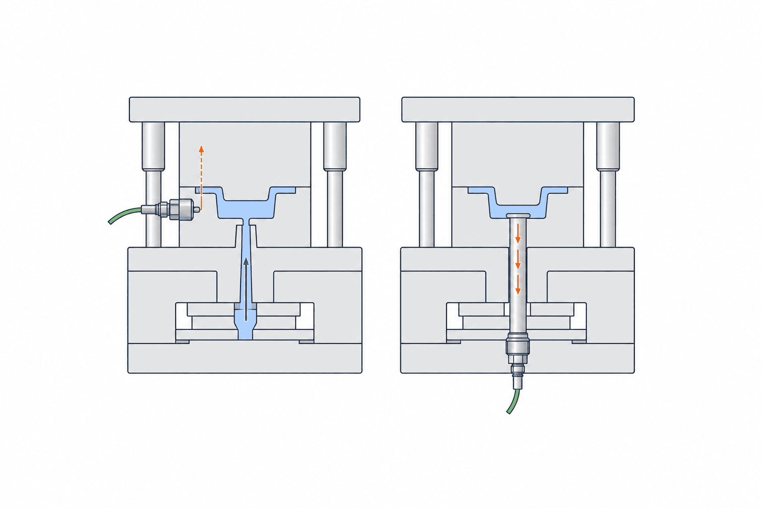
Direct and indirect sensing: compare the entire installed system
A direct sensor contacts the cavity surface and senses plastic pressure at that position. It can capture the local pressure curve but calls for an assessment of surface witness marks, tip installation, wear, contamination, heat and machining. An indirect sensor receives force through an ejector pin. It may suit a tool where a flush sensor is impractical, but pin diameter and projected area, sliding friction, contact and the space behind the pin all affect the signal. RJG’s selection guidance explicitly asks about pin size, expected pressure, mold temperature, clearance and channel count. RJG: Choosing a Sensor
There is no blanket winner. Compare repeatable detection of the chosen defect. For a short shot, the useful location is where normal and defective shots separate clearly. Do not automatically interpret an indirect signal as an absolute direct-pressure reading; document calibration and any conversion assumptions. In supplier comparisons, include not just sensor sensitivity but machining, signal conditioning, connectors, cable routing, spare parts, maintenance and replacement.
Bring tool design, maintenance, process engineering, quality, OT and the sensor supplier to the retrofit review. Compare the mold drawing with the actual tool. Inspect cooling lines, hot-runner wiring, ejector arrangement, connector orientation, crane handling, cable protection, cleaning and storage. Price sensor supply separately from tool modification and include replacement pieces and repair plans. Approve the modification drawing and responsibility boundary before machining. After reassembly, check leakage, release, cooling performance and part appearance.
Read the full curve, not just one peak
The pressure curve reflects filling, packing, holding and cooling during a shot. Comparisons require a reliable trigger and event context: cycle start, injection start, velocity-to-pressure transfer, hold end and mold opening. If press and acquisition timestamps drift, aligned curves may be compared at the wrong phase. State which signal starts acquisition and how missing triggers are reported. Kistler describes ComoNeo as a process monitoring and documentation system using cavity pressure and mold temperature; actual interface capability must still be checked for the proposed configuration. Kistler: ComoNeo
Candidate features include arrival time, rise rate, pressure at transfer, peak, pressure during hold, area under the curve and cooling decay. Turning every feature into an alarm on day one produces overlapping warnings without a clear action. Select a few that matter to the target defect and compare normal, borderline and defective shots with actual inspections. RJG lists peak, transfer pressure, pressure integral and cooling decay among process-fingerprint measures. RJG: Cavity Pressure Data
Limits should come from an approved process and inspected parts, not an arbitrary vendor default or a casual “mean plus or minus” rule. Include multiple shifts, resin lots and normal temperature variation in the baseline. Run intentional boundary trials under quality control. Evaluate both false rejects and missed defects. There is no universal 99% target that can be copied into every RFQ; define the defect, test population, acceptance criterion and approver for this product.
An unusual curve does not prove one root cause. Resin viscosity, drying, regrind, barrel heat, tool temperature, screw wear, check-ring behavior, gate blockage, valve gates or sensor contact can change the signal. Use the alarm to narrow investigation, then review recipes, machine alarms, material history and physical inspection. The HMI should show measured feature, violated limit, shot and cavity, and containment state. Avoid displaying an unsupported automatic diagnosis as fact.
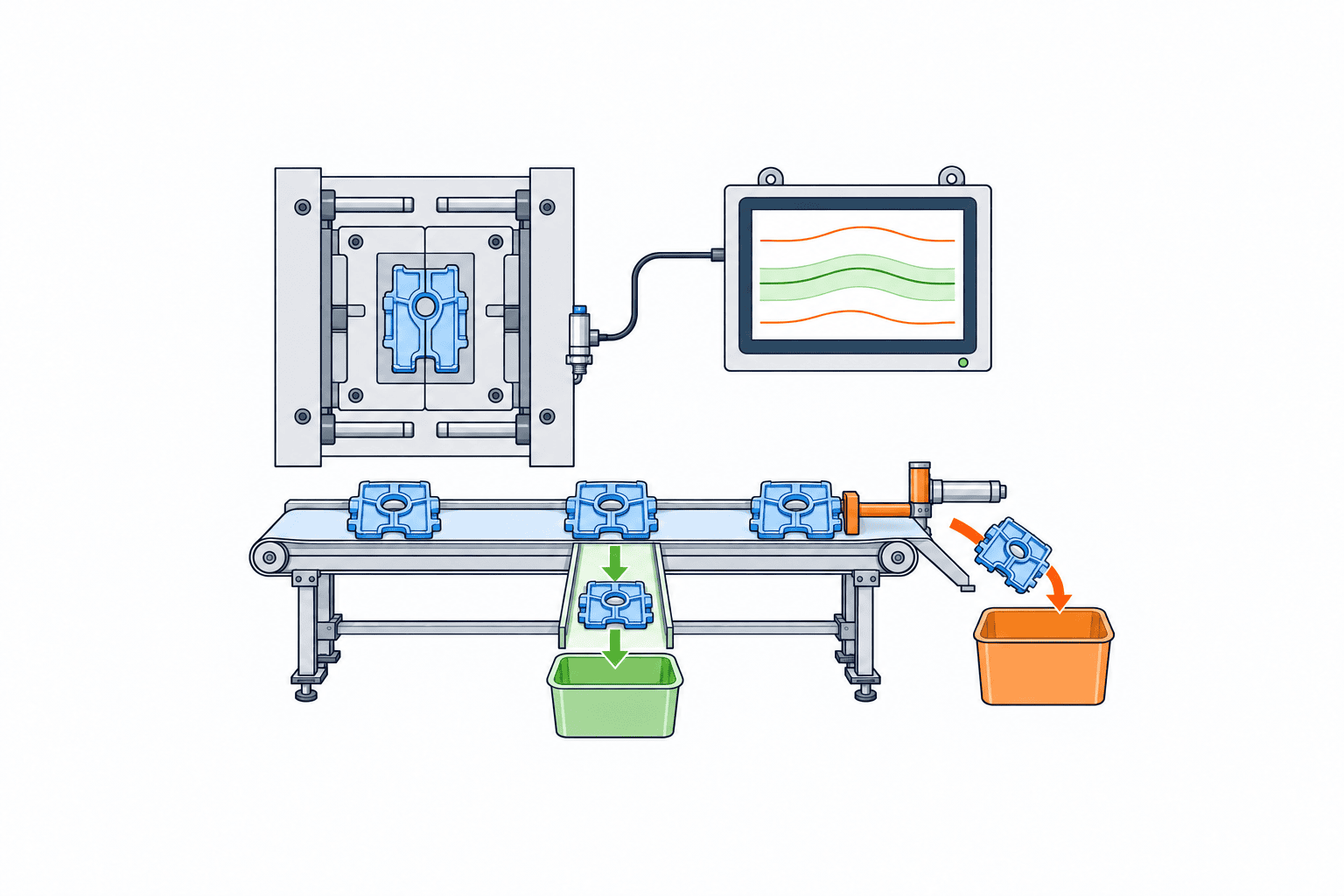
Multi-cavity sorting: separate a cavity decision from physical diversion
Suppose only one cavity of a four-cavity tool has inadequate pressure. Software can identify that cavity, but a robot or conveyor that drops all four parts together cannot necessarily isolate just one. The sorting specification must cover channel mapping, pickup orientation, cavity mapping, transfer path, chute, box change and operator confirmation. A cavity mark on the part does not solve automatic segregation once parts have mixed. Evaluate “cavity-level decision” and “cavity-level physical diversion” as separate capabilities.
Distinguish immediate scrap, hold for inspection and containment of a wider lot. A cable break or missing trigger means “unmeasured,” not “low pressure.” Decide a fail-safe status so unmeasured parts are not silently passed as good. Excessive blanket scrapping can tempt operators to disable the system, so risk-based choices may include a stop, hold-bin routing, increased inspection or quality-authorized release. If an alarm is suppressed, log the reason, effective interval, approver and affected shots.
Feed inspection outcomes back into the monitoring record. A false alarm and an undetected defective part both teach the team something about position or limits. Never overwrite historical rules when a threshold changes. Store recipe revision, rule revision, reason, approver and effective time so the original decision can be reproduced later.
OT and MES integration: keep waveform storage distinct from genealogy
Draw the path from sensor to amplifier or charge amplifier, acquisition unit, edge gateway and quality/MES database. Not every raw sample must be kept indefinitely in MES. One valid design sends decision features, result, waveform reference, shot ID and cavity ID to MES while storing raw curves in a plant time-series store for an agreed period. Customer and product requirements may call for full waveform retention; those requirements take priority. Specify retention, capacity, retrieval time, backup and deletion ownership.
EUROMAP 77 defines data exchange between an injection molding machine and MES. It is useful when planning press-to-MES connectivity, but adopting it does not automatically deliver high-frequency cavity-pressure waveforms from a separate monitoring system. Specify that system’s output, shot events, data format, timestamps, buffering, retry and missing-data handling separately. EUROMAP identifies 77 as the IMM–MES interface and 83 as the common type definitions. EUROMAP 77 EUROMAP OPC UA overview
A timestamp alone is a fragile shot key. Define press-specific cycle number, tool ID, cavity ID, recipe revision, order, material lot, acquisition time and removal result. If the cycle number resets at startup, combine it with press ID and run-session ID. Test clock drift among the press, monitor, gateway and MES. Test power loss, network interruption and buffer overflow: how long data survive, how gaps are shown and whether retry creates duplicate shots. Without physical part marking or box-level association, genealogy cannot be more granular than the mixing that happens on the shop floor.
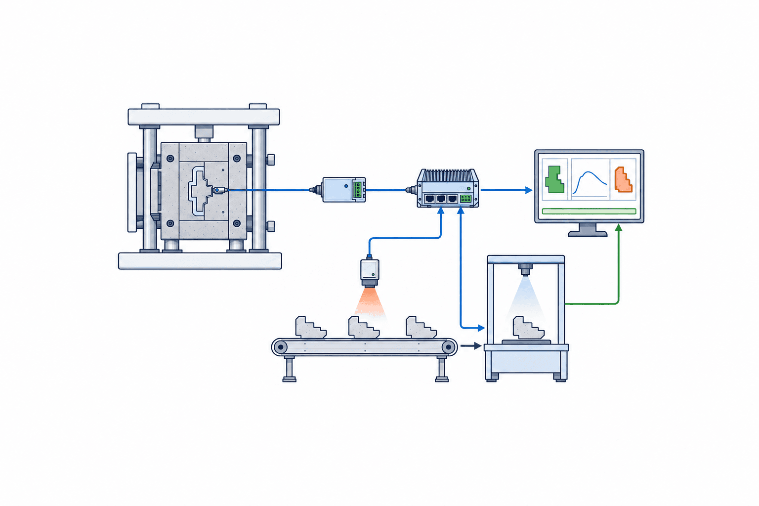
Retrofitting an existing mold: expose downtime and total cost early
A realistic estimate includes tool transport and machining, pin changes, cooling-line adjustments, connectors and cable guards, amplifier and acquisition hardware, press signals, gateway, HMI, MES link, sorting equipment, calibration fixtures, training and spares. Check maintenance contracts and mold ownership. For a customer-owned or externally serviced tool, establish who approves changes, keeps revised drawings and pays for damage. Compare the complete ability to detect, segregate and reproduce a target quality issue, rather than a price per sensor.
Downtime covers tool removal, measurement, machining, assembly, water and leak checks, dry cycling, trial molding, first-article approval and return to production. A press without usable signals may need PLC work or an external trigger. Read-only monitoring and control outputs to a press or robot have different safety review needs. If a quality decision drives a reject mechanism, agree on the safe default and interface ownership with the equipment team. Temporary trial wiring must not be left as the production configuration.
A manageable sequence is current-state survey, defect and tool selection, feasibility check, monitoring-only trial, limit and segregation validation, MES integration, then standardization. Even in a monitoring-only pilot, draw the future physical paths for accepted and held parts. Otherwise, a later production system may raise an alarm while affected parts continue into the same box. Include the required handling changes in the pilot business case.
RFP requirements: ask for evidence and acceptance, not just part numbers
Provide the target part and risk, mold and cavity count, gate and runner arrangement, resin, mold temperature range, press signals, existing systems, segregation granularity and retention period. Ask each bidder why it proposes direct or indirect sensing, a location drawing, the defect it expects each location to detect, what it cannot detect and a replacement procedure. Separate bid lines for sensors, machining, amplifiers, acquisition, software, press interface, sorter, MES integration, installation, calibration, FAT, SAT, training, spares and annual support. State what is standard, optional or excluded.
| Acceptance area | Evidence requested from supplier | Plant decision owner |
|---|---|---|
| Sensor position | Mold drawing, interference review and installation risks | Tooling and maintenance |
| Signal quality | Normal, boundary and abnormal curves; trigger alignment | Process engineering and quality |
| Quality decision | Comparison with inspected parts; false alarms and misses | Quality |
| Sorting | Demonstration of physical cavity or shot diversion | Production and quality |
| Integration | Shot/cavity IDs, recipe revision, loss and retry logs | OT and MES |
| Operation | Calibration, replacement, limit changes and outage procedure | Maintenance and production |
Separate initial from annual spending. Annual cost can include sensor replacement, calibration, software support, storage, supplier service and incremental mold maintenance. Build benefit from your own baseline for scrap, sorting labor, customer escapes and downtime, using only improvement that the pilot verifies. Deduct false-reject loss and hold cost during monitoring outages. Keep assumptions visible so quality and finance can approve the same business case.
FAT and SAT: prove the device, then prove the production flow
At FAT, test sensor/channel mapping, acquisition, shot trigger, limit revision, HMI, outputs, broken cable, communication loss, restart and storage limit. Deliberately generate normal, low, high, missing-signal, wrong-tool, retry and duplicate-event cases and inspect the decisions and logs. Use real waveforms or the target tool where feasible, not only convenient simulated signals. Record what cannot be reproduced at the supplier site as an explicit SAT item.
At SAT, use the actual Thai plant’s press, tool, robot, bins, network and MES. Confirm displayed tool/cavity/recipe and correspondence between shot records and physical parts. Measure false alarms with ordinary production and misses with quality-controlled boundary and defective samples. Agree on sample selection and test population before seeing the result. Demonstrate that a broken cable or network loss routes parts to the intended hold state, and that recovery reveals gaps or duplicates. Inspect the contents of the physical bins, not just an MES screen.
Record who tested which tool, resin and recipe revision, how many shots were tested and how decisions compared with part inspections. Move subsequent limit changes into quality change control. At initial production launch, run monitoring alongside existing inspection until quality approves a reduction in the old check. Equipment acceptance and transfer of quality assurance should be separate decisions.
Boundary Conditions for Measurement and Judgment: Including Shots That Cannot Be Clearly Classified as Good or Bad in Design
During mass production, waveform data does not always fit neatly into the three categories of “normal,” “low pressure,” or “high pressure.” Situations such as startup immediately after mold change, the first shot after purging, manual operation, resin changes, waiting for temperature stabilization, shots aborted mid-cycle, or when a cavity is blocked, all differ from the conditions approved for mass production. Even if the data logger captures a waveform, it is not always appropriate to apply the standard good product judgment rules. In the RFP, define for each process state whether it is “subject to monitoring,” “for reference only,” “automatic hold,” or “molding prohibited,” and require that operators can distinguish these on the HMI. If startup products are later returned to the good product box, record the re-inspector, quantity, range of affected shots, and reason for release in the history.
If a sensor is lost in only one of multiple cavities, whether to stop all shots or hold only that cavity depends on the physical ejection capability and product risk. Assign separate abnormality codes for sensor disconnection, amplifier saturation, zero-point drift, noise intrusion, trigger loss, and mold ID mismatch. If you record “pressure zero due to no signal,” you risk mixing up true short shots with measurement failures, leading to incorrect analysis and response. Save flags indicating measurement validity, reasons for signal quality issues, date of last calibration, and sensor replacement history together with the waveform data. The quality department must decide in advance whether the product isolation range after a failure covers all shots since the last normal shot or traces back to the last inspection pass.
For waveform comparison, the mold, material, and condition version must also match. Even with the same mold, changes in resin grade, color, recycled material ratio, or temperature control settings require a review of the approved normal range. Accidentally recalling a reference waveform from different conditions is a risk distinct from sensor accuracy issues. Store recipe download values and actual measured values, threshold set versions, approval status, and effective start times separately, and ensure that mass production judgment does not start with unapproved combinations. When resetting mid-cycle or rolling back serial numbers, create a new operation session to prevent duplicate IDs. With this exception design, operators can decide what to place in the box during abnormalities without hesitation, and the quality department can later trace the basis for judgments. If you change the sampling frequency or filter settings, re-evaluate whether simple comparison with previous waveforms is still valid. When smoothing to remove noise, check that short-term abnormalities are not also erased by comparing raw and processed signals for the same shot. Record not only the data loss rate but also peak shifts, time shifts, pressure units, and reference differences before and after sensor replacement in the inspection records. Even if the screen display appears stable, the underlying saved data may be incomplete, so include tests to search for specified shots later and reproduce the waveform and judgment.
Additional Conditions for Procurement and Acceptance: Interchangeability, Data Ownership, and Handover of Evidence
When comparing sensor vendor proposals, check not only the initial cost but also the downtime required for replacement and the conditions for substitutes. Whether full disassembly is needed to remove the sensor from the mold, whether only the cable can be replaced, and whether spare parts can be sourced locally in Thailand all affect recovery time during mass production. Require the proposal to specify model numbers and compatibility ranges for sensors, amplifiers, cables, connectors, and software, policies for alternatives when models are discontinued, calibration and inspection frequency, and failure diagnosis procedures. Also confirm the support contact in Thailand, language, response hours, and division of responsibilities with the mold maker. Do not treat the vendor’s stated general lifespan as the factory’s warranty value; instead, plan spares based on the specific mold’s heat, contamination, and handling conditions.
Include data ownership and exportability in the purchase order. Merely being able to view waveforms and judgment results is insufficient when upgrading to another monitoring system or during customer audits. Confirm whether you can bulk export shot IDs, cavity IDs, timestamps, feature values, judgment rule versions, and reasons for missing data in a standard machine-readable format, whether units and time zones are clearly indicated at export, and how many days after contract termination you can retrieve data. For cloud-based systems, specify on-site judgment and local buffer during communication outages, data storage location, access rights, and audit logs. If you only receive proprietary waveform formats, compare the viewing software and long-term usage conditions as well.
Passing FAT/SAT is not satisfied by simply “seeing the curve on the screen.” As delivery evidence, require handover of the mold modification drawings, each sensor’s position and serial number, channel correspondence table, calibration certificate or procedure, wiring diagram, I/O table, judgment rule version, waveforms of normal/boundary/abnormal shots, actual inspection results, communication interruption/recovery logs, records of discharge to hold box, and operation/maintenance procedures. Manufacturing, quality, maintenance, and OT personnel must each sign off on the match between demonstration results and actual equipment. If there are unresolved items at acceptance, clearly document temporary operation, alternative inspections, deadlines, and responsible persons, and do not proceed to mass production with ambiguous “conditional acceptance.”
FAQ
How many cavity pressure sensors should an injection molding pilot use?
Do not set a universal number. Select one tool and one defect, then place sensors at a location suited to the hypothesis, such as post-gate or end-of-fill. If cavities vary individually, a representative point may be insufficient. Document unmonitored cavities and compensating inspection. RJG: Sensor Placement
Is a direct or indirect sensor better for an existing tool?
It depends on tool construction and part requirements. Direct sensing needs acceptable cavity-surface installation and witness marks. Indirect sensing depends on ejector-pin size, contact, friction and space behind the pin. Compare drawings with the actual tool, repeatability, maintenance and calibration, not price alone. RJG: Sensor Choice
Can press injection-pressure data replace cavity sensors?
For some quality questions existing press data may be sufficient. It is not the plastic pressure inside each cavity. Test whether the available signal detects the specific defect before deciding. RJG: Match Outputs, Not Setpoints
Does EUROMAP 77 automatically send cavity waveforms to MES?
No. It addresses IMM–MES exchange; a separate high-rate monitoring system needs its own waveform interface, shot association, features, retention and loss handling. EUROMAP 77
How should cost and payback be estimated?
Break out tool modification, sensors, acquisition, sorting, press and MES interfaces, calibration and support. Use your plant’s actual defect, sorting, escape and downtime baseline plus pilot evidence. Avoid copying a generic improvement percentage. The broader cost model appears in our traceability implementation guide.
Summary: put the quality problem and acceptance criteria on one page
Cavity pressure monitoring is more than adding a transducer. Choose the sensing point from the defect, assess direct or indirect installation and tool modifications, connect curve features to inspected part quality, physically contain abnormal shots, and join shot/cavity records to production history. FAT verifies equipment functions; SAT verifies the real mold and material flow. A useful RFP says which defect must be found in which cavity, with what agreed test set, and where the affected part must go.
If you are still mapping a candidate mold and its defects, contact TOMAS TECH. We can help define the sensor-location hypothesis, retrofit scope, system interfaces and FAT/SAT evidence before selecting a supplier.


