


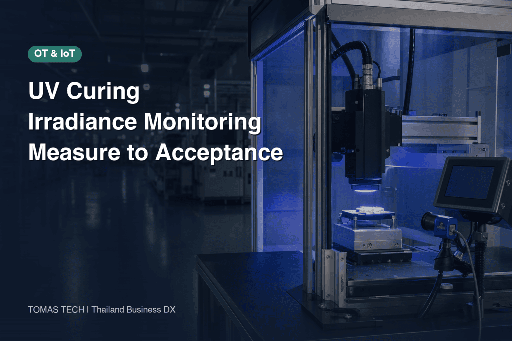
When introducing UV curing irradiance monitoring, saving the lamp’s output setting is not enough to establish a quality record. The useful evidence is light reaching the workpiece at a defined wavelength response, position, angle and exposure condition, linked to the product and lot. This guide takes a Thai factory with an existing spot-curing station or conveyor UV line from instrument selection through data integration, an RFP, factory acceptance testing (FAT) and site acceptance testing (SAT). Acceptance thresholds must come from validation of the actual material and process; no universal “passing irradiance” is assumed here.
When UV curing irradiance monitoring becomes necessary
“We changed the lamp but still had bonding defects.” “The controller output stayed constant while cure variation increased.” “During a customer audit we could not show what a particular lot received.” These situations often arise when a machine setting is treated as if it were the exposure at the product. Distance and angle from the head to the part, dirt on optics or a light guide, conveyor speed, exposure time and temperature can change cure-site conditions without changing the output setting. The first step is not to assign the defect to the lamp. It is to create a reproducible record that reveals which condition changed and where.
On September 29, 2026, Excelitas announced the R2000Plus radiometer for optical-power and irradiance measurement in curing applications. That announcement is a timely example of a vendor emphasizing cure-site verification, records and calibration. It is not a recommendation to buy the product, and its spectral range and logging features are specific to that model. Compare any candidate’s specification with your material and process before selecting it. See the Excelitas announcement.
Four functions should agree on the objective. Maintenance needs evidence of source degradation and a basis for replacement. Process engineering needs repeatable exposure geometry and takt time. Quality assurance needs the relationship between measurements and product tests. IT and OT need dependable collection, identification and retention of records. If only one function specifies the system, a factory may end up with a number it cannot interpret when the recipe changes, or a detailed dashboard whose measurement position cannot be reproduced.
Separate irradiance, energy density and wavelength
Three quantities belong in the first draft of the specification. Irradiance is the instantaneous optical power reaching a stated plane, often expressed in mW/cm². Energy density, or dose, integrates irradiance over exposure time and is often expressed in mJ/cm². Wavelength describes the spectral content that must suit the photoinitiator, the lamp and the detector. Under an ideal constant irradiance, dose equals irradiance multiplied by time. On a real conveyor, both position and time change, so the exposure history matters.
RadTech’s explanation of UV curing describes the combined role of wavelength, irradiance and energy density required by a formulation. The Dymax process guide calls for monitoring intensity at a spot-cure bond line along with cure time, while conveyor processes require attention to energy delivered to the part. A lamp set to 70% output or drawing its rated current does not demonstrate that the workpiece received the validated exposure, nor does it replace a product quality test.
“UV” is not a single interchangeable wavelength. Many LED curing processes use UV-A or wavelengths close to visible light; other sources have broader spectra. UV-C is not the default for every curing line. Put the material supplier’s cure information, the actual source spectrum and the detector’s spectral response side by side. Hamamatsu notes that readings can differ from the actual value if the measurement source spectrum differs from the calibration wavelength. Its UV power meter specification illustrates a question to ask for any proposed instrument, not a universal instrument requirement.
Specify a measurement point on the workpiece, not only at the lamp
A reading at the light outlet helps track equipment changes. A quality claim about the product requires a condition at the bonding line, printed surface, coating surface or other location where cure matters. For a spot head, define the bond-line height and head angle. For a conveyor, define product height and positions across the belt. On a shaped part, include a position likely to receive less light because of distance or shadow. Select representative risk points before attempting continuous monitoring everywhere.
Use a fixture and drawing to define the detector face’s height, X/Y position, orientation and mounting method. If each operator holds a sensor differently, a change in readings cannot be assigned confidently to the lamp rather than the measuring position. For a small light spot, check that the active detector area and illuminated spot align. The Excelitas LS200 is one example designed for direct cure-site measurement. Its suitability still depends on your workpiece geometry, spectral response, irradiance range and available space; its model specifications are not general acceptance limits.
On a conveyor, assess speed, irradiation width, overlap between heads and the exposure profile from entry to exit. Measuring only in the center may miss a low-dose edge. Run a thin sensor or test workpiece at the actual product height and speed, and compare central and side positions relevant to your product. Reflection and shadow from the part also matter. If a sensor cannot be placed safely during production, distinguish a scheduled reference measurement at a stop from an online proxy signal. State which is the product-quality evidence.

Design the monitoring system through product identification
The architecture extends beyond the radiometer. A minimum system comprises the UV source, workpiece, instrument, a fixed measurement method and a record file. For automated production, the meter or lamp controller passes data through a PLC or edge device; part number, recipe, workpiece or lot ID, timestamp and machine ID travel with the measurement into MES. A lone irradiance value cannot support traceability if nobody can identify the part it describes.
An online signal and a periodic measurement with a calibrated reference instrument serve different purposes. The online channel can detect relative change quickly and trigger control or alarms. A direct cure-site reading checks whether that online signal still represents the actual exposure at the workpiece. Do not assume “online value equals product dose” until the relationship has been tested over the intended operating range. Ask whether an embedded lamp sensor sees the source outlet, a light guide, or something representing the workpiece plane.
Interfaces may include a CSV file, USB, serial connection, Ethernet, a PLC or an API. Choose after deciding how long the line may stop, what happens when a record is missing and how retries are reconciled. Our industrial protocol gateway selection guide explores the interface decision in more detail. The essential requirement here is one identifiable measurement event per product or validated sampling unit. Clock synchronization and sequence numbers also matter: if a measurement timestamp drifts from the production record, the affected product interval is difficult to isolate.
Derive alarm thresholds from product tests
A catalog’s maximum irradiance is not a pass threshold. Cure depends on the material, film thickness, substrate, penetration depth, temperature, humidity, pretreatment, exposure time and the required downstream property. A bonded part may need shear or peel evaluation; an ink may need adhesion and abrasion tests; a coating may need hardness and appearance checks. Irradiance is a process variable, not direct proof of finished-product performance.
Start with baseline readings from an established good process. Then test planned variations around candidate upper and lower limits. Change wavelength, irradiance, exposure time or conveyor speed deliberately, including combinations that can occur in production. Connect each measured exposure with a product-test result. Use that evidence to define acceptable, warning and stop ranges. Treat changes outside the validated window as formal process changes rather than letting an operator conclude that “a little more output must be safe.”
The Dymax guide describes determining the lowest acceptable intensity through actual part tests and placing a maintenance decision above that minimum with a margin. It does not supply one transferable percentage for every factory. The margin must consider material and equipment variation, measurement uncertainty, line speed and product risk. Record who approves the threshold and its revision history, and revisit it when the lamp, material or process geometry changes.
Combine calibration, measurement repeatability and maintenance
A calibration certificate alone does not make daily readings comparable. Include the instrument model and serial number, calibration date and validity, applicable wavelength, range, fixture, measurement location and optical cleanliness in the record. Dirt on a detector window or a damaged cable can change a value independently of lamp condition. When a reading suddenly falls, the diagnostic sequence should inspect the sensor, optics, supply, position, workpiece and recipe before declaring the lamp worn out.
Set a calibration interval from the selected manufacturer’s guidance, duty cycle, environment, customer requirements and the factory’s metrology rules. A one-year interval recommended for a particular model is not a universal legal rule for UV meters. If an instrument is overdue or replaced, its ID-to-product linkage lets quality staff identify the affected interval. Distinguish routine reference readings, post-cleaning checks and post-lamp-change readings as different event types.
Overlay measurements with operating hours, switching cycles, cooling condition, lens or light-guide condition and power faults. A simple straight-line extrapolation can create a false replacement plan if a dirty optic or displaced fixture caused an apparent decline. Separate gradual trends from sudden steps and read them against maintenance history. Real-time monitoring earns its place when a change can be connected promptly to the workpieces that might require inspection, not merely because a dashboard has another graph.

Link measurements to workpiece IDs with complete data fields
At minimum, record machine ID, light head ID, meter ID, measurement location, spectral band or detector filter, irradiance, energy density, units, exposure time or conveyor speed, recipe revision, workpiece or lot ID, time, disposition and exception reason. A missing reading must remain a visible missing event rather than being silently deleted. Sending a bare number to MES without its units and spectral band can mix measurements from different instruments and make later comparisons misleading.
Design the exceptions before rollout: the barcode cannot be read; the same workpiece is irradiated twice; a conveyor stops partway through exposure; power fails and the cell restarts. Do not overwrite the first event with a successful second exposure. Preserve the original and link a rework event. If the equipment identifies only a lot, do not promise unit-level exposure proof; document what the lot sample can represent. The same identification principles appear in our article on the cost and payback of automatic inspection-data collection.
Agree on what happens when the meter or network is offline: whether production may continue, what temporary manual record is valid, how it is imported after recovery and who approves retrospective disposition. Conflating a quality failure with a brief communications failure leads either to avoidable stops or to production without an accountable record. If retries can create duplicate messages, use an event ID so MES processes them idempotently. Verify that clocks and event sequences remain aligned after a PLC or server restart.
Questions to put in the RFP
“Supply one UV monitoring system” does not make a comparable RFP. Give vendors a drawing of the cell, UV source model and spectrum, material, workpiece envelope, exposure height and speed, and the product quality test. Ask each vendor to specify spectral response, calibration conditions, range, detector aperture, installation limits, repeatable cure-site fixture, relation between online and reference values, ID integration, missing-data behavior, replaceable parts and local support. A generic “UV compatible” claim is not enough.
Break cost into instrument, sensors and fixtures, shielding and safety work, PLC changes, edge device, MES interface, calibration, spares, maintenance and planned line downtime. Separate one-time implementation from recurring metrology and cleaning. Check whether on-site measurement and FAT/SAT attendance are included. There is no defensible fixed market price for all such projects: spot and conveyor applications, existing controller interfaces and required record granularity produce very different designs.
A comparison sheet should distinguish mandatory from scored features. Mandatory items may include spectral fit, safe use with the enclosure, required measurement range, calibration evidence, disposition on a fault and product-ID linkage. Additional points may cover multiple measurement locations, visualization, maintenance analytics and spare availability. Do not score an unverified sales claim as if it were a demonstrated function. When the system joins an external network, process safety, reliability and availability also belong in the IT/OT review, consistent with NIST’s OT security guide.
Move from a focused PoC to FAT and SAT
A proof of concept on a line with frequent rework or customer concerns is easier to evaluate than an immediate full-plant deployment. Define the part, measurement positions, current defect measure, permitted downtime and pass criteria before collecting data. When readings vary, test whether the cause is process variation, changing sensor placement or a spectral mismatch. Keep test workpiece IDs; anonymous mixtures of good and bad parts cannot validate a condition-to-quality relationship.
For a spot-bonding PoC, measure not only the bond section closest to the head but also a point partly shaded by a fixture wall. Keep the production fixture in place. Record head distance and angle, optical cleanliness, adhesive lot and exposure time before each reading. If repeated readings differ, verify fixture repeatability and detector placement first. Do not average away a weak spot. Test bond strength with the planned product method, since adhesive volume and joint gap can change performance even at the same measured irradiance. Keep boundary-test parts separated from production.
For a conveyor coating PoC, carry the measuring sensor at the real workpiece height and speed. Compare left, center and right positions, then measure how each changes with line speed, head replacement and optical cleaning. Record a mid-conveyor stop as a separate event with position and dwell time, not only as a higher dose. Compare the readings with adhesion, appearance or other validated product tests. If they disagree, investigate film thickness, material lot, previous drying, reflection and part orientation. Success means operators can repeat the measurement and use the record to identify which parts require disposition.
At FAT, assemble the instrument, fixture, control panel and data conversion where practical. At the specified simulated part height or with suitable test signals, check values, units, event IDs, alarms and missing-data handling. Check that calibration information and setting revisions appear in the report. FAT cannot guarantee the exposure at the installed workpiece: vibration, temperature, dirt and enclosure clearance at the site may differ.
At SAT, make reference measurements at the real cure point. Test different conveyor speeds, a head replacement, recipe change, meter disconnection, communications loss and recovery, failed ID scan, re-exposure and a line stop. Confirm that maintenance staff can place the detector safely and complete the scheduled check within the available maintenance window. The acceptance record should identify the meter and calibration status, part type, position, relevant environmental conditions, result, deviation and retest.
An acceptance checklist should test more than “data arrived.” With a known part and recipe, confirm that the value, unit and detector ID are stored and retrievable from the part ID. Simulate clock disagreement and verify which clock is authoritative. Disconnect communications and restore them: the same event must not be duplicated, and parts that passed during the gap must be identifiable. Change a threshold in a controlled test and check that both recipe revisions, the operator, approver and effective time remain in the audit history. Simulate an online sensor failure and follow the intended alarm, product hold and permitted manual measurement. These checks prevent a technically connected system from failing the quality audit later.

Decide fault response and safety before production use
A warning-range reading does not automatically prove a defective part, but the decision to keep running must be predefined. Check the latest reference reading, product tests, lamp status and product criticality. For example, a warning may trigger extra inspection, while a stop-range event may require a line stop and product hold. When no measurement exists, “the setpoint did not change” is not adequate evidence by itself; document the basis and approver for any release decision.
Working inside a UV cell can expose personnel to light, electricity, moving parts and hot surfaces. The process should not require disabling safety covers or interlocks to measure. With the plant safety lead, design a fixture placed from a safe position, isolation and lockout for maintenance, and appropriate protective equipment. Write these steps into the operating instruction and have the local safety team check the applicable requirements.
Integration also needs a safe boundary. A gateway reboot or network outage must not unexpectedly change the curing control signal. If remote setting changes are allowed, specify authorization, change approval, audit history and a way to restore the approved recipe. “Encrypted” on a data sheet is less useful than tested fault and recovery procedures at the actual line.
KPIs and payback
Count the outcomes, not only the data points. Compare suspected cure-related rework and scrap, time from anomaly detection to product hold, time to identify an affected lot, expired calibrations, reference-check completion and line downtime before and after installation. If material, fixtures or work instructions change at the same time, note them so the value of irradiance monitoring is not overstated.
Potential benefits include avoided rework and customer response, less manual checking, better timing of lamp replacement and faster audit evidence. Early validation may actually increase product testing and measurement labor. Use PoC results on baseline values, checking time and fault handling before estimating return on investment; a generic payback month stated before measurement is unreliable.
Operating records and training for the shop floor
Give operators a short instruction showing the measurement point, fixture sequence, meter check, safe start and finish, limits, first response by alarm and location of records. Make calibration evidence and threshold-change history reachable from the production record. Train with realistic examples: a constant lamp setting but different workpiece reading, a displaced fixture, an overdue meter and a short network outage. Show whether each alert goes to maintenance, process engineering or quality. During the first month, review missing events, manual changes, false alarms and time required for routine checks. A stable irradiance without workpiece IDs cannot support traceability; perfect ID linkage at the wrong wavelength or position cannot support quality decisions.
Specify retention separately for raw measurements, dispositions, calibration certificates, recipe revisions and change approvals, considering customer agreements, product life and audit frequency. When records move to MES or cloud storage, reconcile counts, missing events, timestamps, units and rounding before deleting instrument-side data. Test a recoverable backup and whether exported names in Thai or Japanese remain legible. Assign calibration to the metrology owner, optics and fixture maintenance to maintenance, threshold approval to QA, and communications recovery to IT/OT. Name a deputy who can authorize product hold or release. Revalidate spectral response, measurement geometry and limits when a different lamp or material is introduced; identical data fields do not make the values directly comparable across cells.
FAQ on UV curing monitoring
Is the UV unit’s built-in sensor enough?
Check whether it sees the source outlet or a value representative of the workpiece. It can be useful for change detection while missing effects of distance, dirt and shadow. Validate its correlation against a calibrated cure-site measurement over the intended operating range.
Should a line record irradiance or dose?
For spot curing, combine cure-site irradiance with exposure time. For a conveyor, energy delivered during passage is especially important. Neither value alone guarantees product performance; wavelength, geometry, material conditions and product-test results also matter.
Should we buy a UV-A or UV-C meter?
Start from the source spectrum and the material’s cure requirements. Check the detector’s spectral response and calibration wavelength. UV-C is not a default requirement for curing; select an instrument matched to the actual process.
What drives implementation cost?
Number of points, sensor and fixture design, safety and line changes, PLC/MES integration, calibration and spares. Compare bids against the same wavelength, position, test scope and data fields. A meter-only price misses the cost of operating a defensible process.
Can SAT be skipped after a successful FAT?
No. FAT tests the assembled system and data handling. SAT tests the installed workpiece plane, line speed, environment, outage behavior and operator procedure. Define separate pass criteria for both.
Conclusion: define measurement conditions before choosing hardware
An effective UV curing irradiance monitoring project begins by defining which workpiece surface is measured, at what wavelength, position and time, and whether irradiance or energy density is needed. Product tests establish the allowable process window. Calibration, fixtures, maintenance and product-ID records then help isolate affected parts when something changes. Specify safe measurement and FAT/SAT alongside the instrument and data interface in the RFP.
If your Thai factory is still defining measurement locations or record fields for an existing UV curing cell, contact TOMAS TECH. We can help scope a focused PoC and a practical path from equipment data to product records.


