


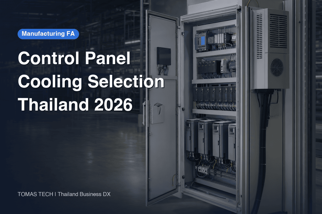
When designing the thermal management of control panels and selecting cooling methods, simply ordering based on the nameplate capacity of a panel cooler can lead to summer shutdowns, condensation, clogged filters, and increased maintenance costs. Especially in Thai factories, it is essential to check not only the average temperature of air-conditioned rooms but also the maximum ambient temperature at the actual installation site, humidity, dust, door opening frequency, and plans for future expansion. This article organizes the process from heat dissipation calculation, comparison of fans, heat exchangers, and coolers, to preparing RFQs and acceptance methods for FAT and SAT, from the perspective of those ordering control panel fabrication or modification.
The First Step in Control Panel Thermal Design: Defining the “Protected Temperature”
It is safer not to start with a uniform target such as “35°C inside the panel.” First, check the ambient temperature range, required clearance on all sides, mounting orientation, and derating conditions specified by the manufacturers for each device inside the panel, such as inverters, servo amplifiers, PLCs, industrial PCs, power supplies, UPS, and communication equipment. The “ambient temperature” in a device’s datasheet may refer to the air near its intake or its installation environment, which is not necessarily the same as the average value indicated by a single panel temperature sensor. Set the design value based on the strictest device requirement and the impact of failure on production.
Next, determine the “maximum ambient temperature” at the installation site. Use a measured or well-founded upper limit that includes peak equipment operation, proximity to furnaces or dryers, mounting near the ceiling, gaps to walls, direct sunlight, and hot piping—not just the air conditioning setpoint in the design office. If the outside air is hotter than the panel’s target temperature, a filter fan alone cannot keep the panel below the target. Consider closed-loop systems such as panel coolers that can achieve temperatures lower than the ambient. nVent’s selection guide also includes the temperature difference between ambient and allowable panel temperature, as well as heat entering through the panel surface, in the cooling load. nVent Selection Guide
Separate “allowable temperature” from “alarm temperature.” The allowable temperature is the design upper limit considering device specifications and lifespan, while the alarm temperature is set lower so maintenance can respond before reaching the limit. The shutdown threshold is a design decision for safety and equipment protection, so do not simply adopt the cooler’s default settings—ensure agreement between control designers and production. If panel humidity is high, lowering temperature alone may risk condensation. Also check temperature changes during startup/shutdown, door opening, cleaning processes, and the dew point of cooling surfaces.
Aggregate Heat Load by Equipment Power Dissipation, Not Rated Input
If you sum up all devices’ “rated power” as heat, the cooling equipment will be oversized. The actual heat generated inside the panel is mainly from equipment power dissipation. For inverters and servo amplifiers, check the losses according to operating load and switching conditions; for power supplies, consider efficiency losses; for transformers, check iron and copper losses; for resistors, use actual operating power. Prioritize values provided by manufacturers as “power dissipation” or “heat loss,” and record simultaneous operation combinations for devices with multiple operating modes. Rittal recommends summing the heat dissipation of all devices installed in the panel and using the maximum ambient temperature, maximum internal temperature, and panel dimensions to determine the required cooling capacity. Rittal Thermal Design Guide
If dissipation data is unavailable, contact the equipment manufacturer with the model and operating conditions. If you must estimate, clearly label it as “assumed,” and replace with measured or finalized values before FAT. For future expansion of servos or IPCs, list specific planned devices, dissipation, and installation locations separately, rather than using an arbitrary margin factor, to make estimates easier to compare. Adding devices may block airflow, so simply increasing cooling capacity will not solve the problem.
Do not ignore heat transfer through the panel walls. When the panel interior is warmer than the outside, heat can dissipate through the walls; when the outside is hotter, heat enters the panel. Rittal’s guide treats panel surface heat transfer as a function of effective surface area, heat transfer coefficient, and the temperature difference between inside and outside, explaining that required cooling capacity increases or decreases depending on conditions. Counting all surfaces—including those against walls or adjacent panels—as freely radiating can lead to under-design. For outdoor installations, also consider solar radiation, rain, and waterproofing.
| Item to Aggregate | Value to Provide in RFQ | Points to Confirm |
|---|---|---|
| Equipment Power Dissipation | Model, quantity, W per operating mode | Do not confuse rated input with dissipation |
| Ambient Temperature | Maximum value and measurement conditions at site | Do not substitute with air-conditioned room average |
| Target Panel Temperature | Upper limit based on strictest device | Specify sensor location |
| Panel Dimensions & Installation | Width, height, depth, adjacent panels, wall, indoor/outdoor | Confirm effective heat-radiating surfaces |
| Humidity & Contamination | Condensation, dust, oil mist, cleaning, water drops | Determines open or closed system |
| Future Expansion | Additional devices, estimated dissipation, required space | State margin rationale separately |
Example: How to Interpret Estimated Heat Load
The following is a hypothetical example for method comparison and is not a product rating or recommended capacity. Assume total equipment dissipation inside the panel is 600 W, maximum ambient temperature at the installation site is 40°C, and target internal temperature is 35°C. Since the outside air is 5 K higher than the target, heat flows into the panel through the walls. Assuming an effective surface area of 3 m² and a heat transfer coefficient of 5 W/(m²·K) under actual conditions, the simple heat influx through the panel wall is 3×5×5 = 75 W, making the total load estimate 675 W. However, the coefficient varies with panel material, layout, airflow, insulation, and wall contact; solar radiation, door opening, and local hot spots are not included in this number. Re-enter these conditions into the manufacturer’s selection tool and adjust the rated cooling capacity for the actual ambient temperature before conducting field tests.
This example does not mean “a 700 W-class unit is always sufficient.” The catalog capacity of cooling units depends on test conditions; check the actual capacity at 40°C ambient and the heat rejection space on the condenser side. Local hot spots may cause some devices to exceed 35°C. Before deciding on a cooling method, confirm both the load and available space on the drawings. nVent’s selection guide and Rittal’s RiTherm provide primary data for such comparisons. nVent Cooling Selection Tool / Rittal RiTherm
Comparing Filter Fans, Heat Exchangers, and Panel Coolers
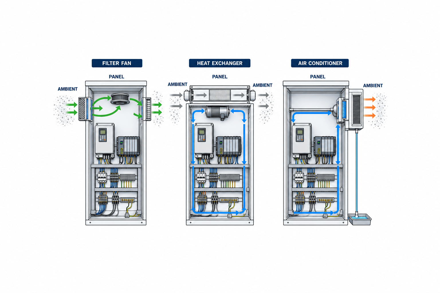
Filter fans are open-loop systems that draw in outside air to exhaust heat from the panel. Where the outside air is sufficiently cool, dust and oil mist are controlled, and the required protection rating can be maintained, the configuration is relatively simple. However, if the outside air is hotter than the panel target, increasing ventilation cannot lower the panel temperature below the outside air. As filter clogging reduces airflow, select units considering cleaning/replacement frequency and monitoring of differential pressure or temperature. Adding openings affects the panel’s protection rating, so confirm the combination of panel, fan, and filter.
Air-to-air heat exchangers transfer heat without mixing internal and external air. They are candidates when you do not want to introduce dust into the panel, but they require the outside air to be cooler than the inside to reject heat. Capacity depends on the temperature difference between inside and outside, so check the selection chart carefully for sites where this difference is small during hot periods. For liquid cooling, separately evaluate water quality, leak prevention, piping, and maintenance. Not all heat exchangers can cool the panel below high ambient temperatures just because they are sealed.
Panel coolers use refrigeration cycles or similar methods to control the panel temperature below the outside air. They can handle high ambient temperatures and large heat loads but require power, heat rejection, installation space, condensate management, and cleaning of filters and condensers. If the intake/exhaust on the panel exterior is blocked, capacity drops, so include clearance from walls and adjacent panels in the specifications. nVent clearly states that heat enters through the panel walls when cooling the panel below ambient, and Schneider Electric lists ventilation, heat exchangers, coolers, and anti-condensation heaters as separate options for electrical panels. nVent Selection Guide / Schneider Electric Thermal Management Products
| Method | Can Lower Panel Below Ambient? | Air Mixing | Key Points to Confirm |
|---|---|---|---|
| Filter Fan | No | Yes | Ambient temp, dust, filter maintenance, protection rating |
| Air-to-Air Heat Exchanger | Generally No | No | Panel/ambient temp difference, required capacity, external contamination |
| Panel Cooler | Yes | Usually closed system | Capacity at ambient, heat rejection, condensate, power |
This comparison table is a starting point for initial selection. In practice, mounting method, panel material, hygiene requirements, corrosive atmosphere, cleaning frequency, redundancy, spare parts availability, and production downtime losses are also decisive. Do not compare only catalog prices; request total cost including installation, annual maintenance, filter/condensate handling, and recovery after failure. When quoting figures, specify the factory’s electricity rate and operating hours as estimate conditions.
Panel Layout and Airflow: Why Cooling Capacity Alone May Not Prevent Shutdowns
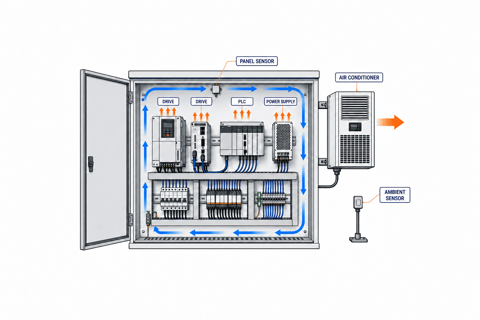
Even if the calculated cooling capacity is sufficient, if intake and exhaust short-circuit, local temperatures will not drop. Hot air may accumulate above inverters or servo amplifiers, panel ducts may block discharge, tall devices may shield cool air, or temperature sensors may be placed directly in the cold airflow—these issues are often missed during commissioning. Follow device manufacturers’ clearance requirements and request a layout diagram with arrows showing airflow from intake, past heat sources, to exhaust or cooling unit return.
Within the same panel, the arrangement of temperature-sensitive PLCs or IPCs and high-heat devices affects results. Avoid placing sensitive devices above high-heat sources; if necessary, separate them by compartment or into another panel, and maintain adequate wiring duct space. Such design changes may be more rational than simply upsizing the cooler. However, new air partitions can create additional hot spots, so judge by both drawings and measurements.
Door opening and cable entry are also part of thermal design. If gaskets are damaged or cable entries are not properly sealed, even a closed system will admit humid air and dust, increasing filter load and condensation risk. In areas where panels are washed, check the washing direction and pressure, panel opening locations, and cooler condensate drainage. If filters are placed where cleaning staff cannot access them, maintenance planning becomes superficial.
Humidity, Condensation, and Dust: Commonly Overlooked in Thai Factories
Do not simply assume all Thai sites are “hot and humid”—investigate the panel’s installation area. Conditions differ for air-conditioned electronics lines, equipment near outdoors, machining lines with cutting oil mist, and washing areas. At minimum, record temperature and humidity during operation and shutdown, door opening frequency, dust and oil mist characteristics, water exposure direction, and nighttime air conditioning operation. Consider dew point, not just temperature, because condensation can occur when cooled surfaces or components contact humid air after shutdown.
Schneider Electric lists anti-condensation heaters as an option in addition to temperature management. This shows that “heaters are unnecessary in hot countries” is a misconception. If condensation is an issue during nighttime shutdown or outside air intake, consider humidity sensors, heaters, ventilation methods, and door opening procedures for the entire panel. For panel cooler condensate, a simple drip tray may not suffice—check drainage route, blockage detection, and ensure water does not drip onto the floor or electrical equipment during SAT. Schneider Electric Thermal Management Products / nVent Temperature Management Guide
When using filter fans in dusty areas, define not only regular cleaning but also “when to clean.” Record airflow or panel temperature before and after filter replacement, and adjust maintenance intervals based on actual data. If oil mist causes clogging, check filter material and replacement methods in advance. If dust cannot be allowed inside the panel, prioritize closed systems and have the contractor demonstrate that both protection rating and cooling capacity can be achieved.
Essential Conditions to Include in the RFQ (Request for Proposal)
Specifying only “control panel cooler set” leads to different assumptions by each contractor, making price comparison impossible. The RFP should clearly state the panel’s purpose and shutdown impact, device list and dissipation, site temperature and humidity, allowable panel temperature, panel dimensions and installation constraints, dust/water/oil mist, required protection rating, power supply, monitoring signals, and maintenance system. Before fixing on a single method, ask candidates to explain why they recommend a filter fan, heat exchanger, or cooler, with selection calculations and usage conditions, so you can compare performance and maintenance costs.
The quotation must specify “capacity units and test conditions.” For panel coolers, check not only catalog nominal capacity but also net cooling capacity and power consumption at the site’s maximum ambient and target panel temperature, and required clearance outside the panel. For filter fans, check actual airflow with filter installed, operation policy when dirty, and replacement parts. For heat exchangers, check capacity curves for different panel/ambient temperature differences. Include temperature alarms, shutdown conditions, and communication targets for power failure or cooling failure in the control specification.
| RFP Item | Specify the Following (not just examples) |
|---|---|
| Temperature Conditions | Site maximum ambient, panel target, alarm and shutdown thresholds |
| Heat Dissipation | Dissipation W per model, simultaneous operation, future expansion details |
| Environment | Humidity/dew point, dust, oil mist, cleaning, water drops, indoor/outdoor |
| Panel Structure | Dimensions, material, clearance to wall/adjacent panels, openings, protection rating |
| Cooling Equipment | Capacity under usage conditions, power, heat rejection, condensate, noise, maintenance |
| Control | Sensor locations (temperature/humidity), alarms, fault contacts, shutdown logic |
| Handover | Calculations, circuit diagrams, BOM, FAT/SAT records, maintenance procedures, spares |
For existing panel modifications, site surveys are more important than for new installations. Nameplates and drawings alone do not reveal added wiring, lack of spare space, deformed doors, old gaskets, distance to walls, or available power capacity. Do not finalize estimates based only on site photos; check panel interior/exterior dimensions, current device temperatures, cable entries, and maintenance access before judging feasibility. If the panel itself needs renewal, compare with the cost of retrofitting cooling equipment.
Cost Comparison: Separate Initial and Operating/Shutdown Costs
Cooling method costs are not determined by equipment price alone. Initial costs include panel modification, power work, installation, ducting/piping, condensate, temperature monitoring, and testing. Operating costs include power consumption, filter/condenser cleaning, replacement parts, periodic inspections, and the impact of failures and production downtime. Do not simply copy manufacturers’ energy-saving rates or lifespans into your cost tables; check if they match your own temperature conditions, operating hours, and load factors.
For example, “annual electricity cost = average actual power consumption (kW) × annual operating hours (h) × contract rate” is a simple formula, but if you equate average actual power consumption with catalog maximum, the evaluation will be off. Assume utilization and temperature variation in the estimate, and update with actual measurements after commissioning. For filter fans, even if power is lower than coolers, add cleaning labor and downtime when airflow drops due to dust. For coolers, actual capacity and heat rejection at high temperatures are critical; do not draw conclusions from simple W-per-price comparisons.
Before ordering, present the same RFP to multiple companies and compare assumptions, exclusions, spare part lead times, and local Thai maintenance contacts in the same columns. Do not treat low-priced proposals that do not meet specifications as “equivalent.” On the other hand, buying oversized equipment does not guarantee peace of mind—airflow, condensation, and space constraints remain. Prefer quotations that can explain price differences in terms of performance, maintenance, and installation scope.
Include items not covered by the price in the comparison table. If panel drilling, reinforcement, relocation of existing wiring, crane or high-place work, weekend installation, production attendance during commissioning, drawing updates, or maintenance training are “excluded,” the budget will balloon after contract. For imported equipment, check how to obtain replacement parts in Thailand and whether substitutes can be installed in the same opening in case of failure. Even if the initial estimate is low, if recovery from cooling failure takes several days, the production evaluation changes.
If updating multiple panels at once, do not simply average the heat load across all panels. Panels near machines, near the ceiling, or on exterior walls have different ambient conditions. While creating common specifications, determine method and capacity for each panel based on its heat sources and installation location. Standardizing cooler models makes spare management easier, but first confirm it does not cause under- or over-sizing.
What to Inspect in FAT and SAT
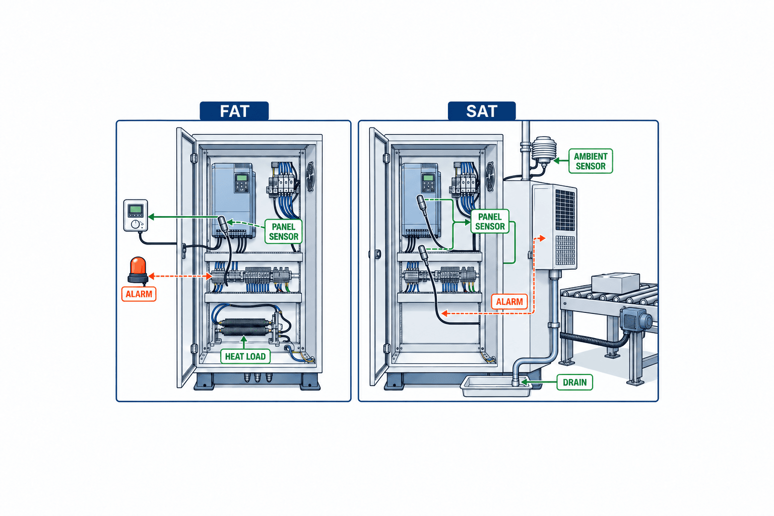
FAT (Factory Acceptance Test) is the stage before shipment to confirm consistency between drawings and assembly, device models, wiring, alarms, temperature sensor locations, cooling unit start/stop, condensate routing, and seals affecting protection rating. If simulating heat load in the actual panel, record the heat amount, location, duration, and room temperature, and clarify differences from site load. Maintaining “35°C inside the panel” in an air-conditioned factory test room does not certify passing at the Thai site’s maximum ambient. Recognize differences in test conditions and leave SAT acceptance criteria open.
SAT (Site Acceptance Test) is conducted at the installation site. Operate the equipment not only under normal conditions but also with realistic combinations that maximize heat load, and measure at representative points outside and inside the panel, especially near the most critical device’s intake. If testing on a day when ambient is below the design maximum, do not simply pass by converting the temperature difference; agree on the manufacturer’s capacity curve, additional test plans, and re-verification deadlines. Record sensor calibration, instrument models, measurement intervals, and stability criteria.
Test not only cooling capacity but also failure responses. Simulate fan stoppage or cooler faults safely, and check if alarms reach the correct recipients and if the shutdown procedure is consistent. Confirm that maintenance can detect filter clogging, condensate drains to the right place, there are no gaps at door gaskets or cable entries, and that heat rejection outside the panel does not adversely affect work areas. Saving temperature logs after operation as a baseline makes it easier to judge seasonal changes or degradation due to contamination.
Write FAT/SAT Acceptance Criteria by Value and Location
A vague condition like “no overheating” leads to different interpretations by vendors and buyers. Tabulate each measurement point, operating condition, duration, ambient temperature/humidity, panel temperature upper limit, alarm thresholds, and abnormal response. Align the temperature upper limit with the weakest device’s manufacturer specification, and do not estimate device internal temperature from air temperature alone. If the design maximum ambient cannot be reproduced in testing, separate what was verified from unverified items at handover.
Acceptance records should include panel ID, drawing revision, cooling equipment model, instrument calibration status, measurement start/end times, operating load, temperature logs, photos, corrective actions, and retest results. This allows consistent re-evaluation even if the contractor changes. In maintenance handover, include inspection intervals for filters, condensers, and drains, replacement parts, emergency contacts, and authority to change settings.
Decision Sequence for Modifying Existing Panels
If you find an existing control panel is overheating, do not immediately add a cooler. First, measure temperatures during shutdown and operation and identify heat sources. Causes may include drives added later, blocked vents, aged fans, clogged filters, doors that do not close, or radiant heat from nearby equipment. Separate issues that can be resolved by maintenance from those due to insufficient design capacity.
Next, check if the current panel structure can support additional cooling equipment. Side-mounted coolers affect panel wall strength, openings, protection rating, door operation, and wall clearance. Also check power capacity and protection devices, alarm wiring for shutdown, and safe condensate drainage. Modifications may change the protection rating guaranteed by the panel manufacturer, so clarify responsibilities among panel maker, cooling equipment maker, and control designer in the RFP.
If the existing panel has high heat load, many planned expansions, or is overcrowded, also consider enlarging the panel or splitting heat sources into another panel. Even if a retrofit cooler seems cheaper, if it eliminates maintenance space or wiring margin, long-term upgrade options are lost. Article on Control Panel Design and Manufacturing for Thai Factories is also useful when considering panel structure and scope of work.
Integration with Related Automation Equipment
Thermal design of control panels is not isolated to the panel itself. When equipment is added, losses from motor drives and power supplies increase, changing the panel’s heat load. For example, when adding a conveyor line, feed the drive method and number of simultaneous operations determined in Roller Conveyor Selection back into the panel design. If adding parts feeders, check how the control equipment and air sources chosen in Automatic Screw Feeder Selection affect the panel load.
If you change the model of PLC or drive, do not reuse previous thermal calculations—update the dissipation list. Ensure mechanical, electrical, and maintenance teams all reference the same BOM and layout revision to avoid post-delivery blame over “why the cooler is insufficient.” Include the thermal design calculation sheet in the same revision control as panel drawings, equipment datasheets, and test logs.
Design Measurement Points and Maintenance Logs in Advance
Thermal design is not a one-time calculation at delivery. If you place the panel temperature sensor just before the cooling unit outlet, the displayed temperature may be low while the intake of heat-generating devices is hot. When deciding measurement points, consider the most temperature-sensitive device, largest heat source, upper panel hot spots, and cooling unit return. Not all require permanent sensors, but decide which points to measure in FAT/SAT, and distinguish between permanent and temporary points. Record ambient temperature and humidity simultaneously, or it will be hard to distinguish seasonal changes from cooling performance degradation.
Sensor readings should be actionable for managers. Maintenance procedures should specify the order of checks: inspect filter condition if an alarm occurs, clean the condenser, check door and gasket, and confirm nearby heat sources. Connecting fault contacts to a PLC is meaningless if no one monitors the screen. Decide notification recipients, nighttime contacts, authority to stop equipment, and recovery conditions. While the Switchgear Condition Monitoring and Partial Discharge Article covers electrical degradation monitoring, the practice of linking temperature logs to equipment ID and timestamp is common to both.
Maintenance history should include not only temperature but also filter replacement dates, pre/post-cleaning status, cooler error codes, drain inspections, and dates of device additions inside the panel. For example, if panel temperature gradually rises, you cannot tell if it is due to filter clogging or increased production unless you compare under the same ambient and load. If temperature rises after adding an inverter, update the dissipation table before suspecting cooler failure. These records also improve the accuracy of estimates for future panel builds.
How to Link Cooling Failure to Equipment Shutdown
If every temperature alarm immediately stops equipment, unnecessary shutdowns will increase. On the other hand, ignoring cooling failures leads to device protection trips or reduced lifespan. If using two-stage alarm and shutdown, specify in the control specification which temperature and duration triggers an alarm, whether load can be reduced, and what is the safe shutdown sequence. Include sensor disconnection and communication errors as detection targets—do not treat “no reading” as “normal.” If changes to safety circuits or protection functions are needed, return to equipment risk assessment rather than leaving it to the panel builder alone.
It is common that SAT cannot reproduce the maximum ambient temperature until the summer peak. In that case, record “conditions confirmed at shipment,” “conditions confirmed on site,” and “unconfirmed maximum temperature conditions” at handover, and set a date and responsible person for re-verification. During the first hot season, check temperature logs and alarm history, and compare actual values with the heat load assumptions used in selection. Including this review enables maintenance staff to detect anomalies early and judge whether further equipment expansion is possible.
Frequently Asked Questions
Is a filter fan alone sufficient for control panel cooling?
It depends on the allowable panel temperature, maximum ambient temperature, equipment dissipation, dust, and protection rating requirements. If the outside air is hotter than the panel target, a fan alone cannot achieve the target. Even if outside air is cool enough, consider filter clogging and internal airflow short-circuiting. Check the dissipation table and site maximum temperature before deciding on a method.
How do you select the capacity (W) for a control panel cooler?
Include not only the sum of equipment dissipation but also heat through the panel walls, solar radiation if outdoors, site maximum ambient temperature, and target panel temperature. Catalog nominal W depends on test conditions, so check net capacity under site conditions using the manufacturer’s selection chart or tool. Clearly state the reason for any margin and separate the internal airflow design.
Does a sealed control panel prevent condensation?
Even sealed panels can admit humid air through door opening, gasket deterioration, cable entries, or temperature changes during shutdown. Also check for situations where cooled surfaces fall below the dew point. If necessary, include humidity monitoring, anti-condensation heaters, condensate management, and operating procedures in the design.
How do you request control panel fabrication or cooling modification for Thai factories?
Prepare an RFP with panel model and drawings, equipment dissipation list, site maximum temperature and humidity, dust/water/oil mist, panel target, installation space, and maintenance requirements. Ask candidate contractors to present method and calculation rationale, installation scope, FAT/SAT acceptance criteria, and local maintenance contacts under the same conditions. For existing panels, include a site survey in the estimation process.
Conclusion: Design the Panel and Site Together Before Buying Cooling Equipment
Control panel thermal design involves confirming equipment dissipation and site maximum temperature/humidity, considering heat transfer through panel walls and internal airflow, and selecting the cooling method. Whether you need a panel temperature below ambient, can allow dust ingress, or how to manage condensation determines the suitability of filter fans, heat exchangers, or panel coolers. Write assumptions and acceptance criteria in the RFP, verify assembly and control in FAT, and confirm actual installation conditions in SAT to reduce rework after purchase.
If you are considering new control panels or cooling modifications for existing panels in a Thai factory, you can consult TOMAS TECH even before your equipment list and site conditions are finalized. We will work together from heat load estimation, cooling method comparison, site survey, to organizing FAT/SAT criteria.
Reference Information
- Rittal, Industrial Enclosure Solutions (2026) — Selecting climate control from heat load and ambient conditions as part of the complete enclosure.
- Rittal, Enclosure climate control — Approach to total dissipation, panel surface heat transfer, and required cooling capacity.
- Rittal, RiTherm — Selection tool for entering panel dimensions, heat dissipation, and ambient conditions.
- nVent HOFFMAN, Selecting a cooling solution — Heat load through panel walls and selection criteria.
- nVent HOFFMAN, Managing & maintaining temperature in enclosures — Open vs. closed cooling, maintenance.
- Schneider Electric, Thermal management of electrical panels — Product range for ventilation, heat exchange, coolers, anti-condensation heaters.
- Schneider Electric, ProClima — Thermal design and method selection for electrical panels.
- Schneider Electric, Electrical Switchboard Design Best Practices — Design guide including ambient conditions, heat sources, and panel structure.


