


When replacing an industrial temperature controller, matching the old panel cutout is only one small part of the decision. The sensor, heater, switching device, protection circuit and production acceptance criteria form one control loop. A more capable PID controller cannot correct a misplaced probe or an undersized heater. This guide gives production engineers, maintenance teams and buyers in Thai factories a practical sequence from the first site survey to the request for proposal (RFP), factory acceptance test (FAT) and site acceptance test (SAT).
Define the thermal loop before selecting a controller
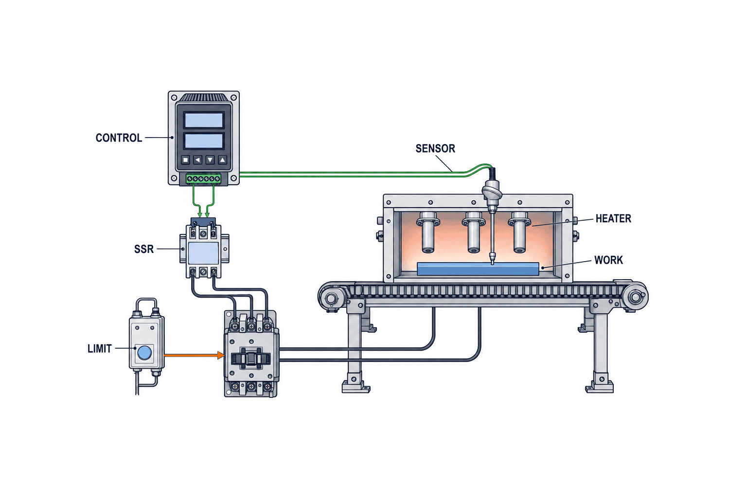
A controller compares the process value (PV) received from a sensor with the set value (SV) and determines an output to a heater or cooling device. OMRON’s technical guide describes this feedback principle. Selection starts with four locations: where quality depends on temperature, where it is measured, where heat enters, and where heat is lost. They may not coincide. A thermocouple embedded in a sealing bar can report a different temperature from the surface touching a film. Air temperature in an oven does not always represent the temperature of a moving workpiece.
Production, quality and maintenance should agree on which measured value represents the process. Record the acceptable temperature band, warm-up and hold times, product and load conditions, door-opening or loading disturbances, and how recovery will be judged. Distinguish a controller that actively regulates one heating or cooling process from a factory-wide temperature monitoring system that collects and reports many values. Pressure-sensor and load-cell selection have different measured quantities and failure modes; sharing words such as “input” and “calibration” does not make them substitutes for a thermal-loop specification.
| Question | Site evidence | RFP output |
|---|---|---|
| What is heated or cooled? | Equipment, workpiece, recipe and operating modes | Defined process boundary |
| Which temperature matters? | Product-quality point and sensor position | SV, permitted band and test point |
| What changes the load? | Feed rate, door opening, ambient conditions | Worst credible operating cases |
| How is power applied? | Heater, valve, contactor or SSR | Output and switching requirements |
| What happens on failure? | Existing protection and stop sequence | Independent protection and restart rule |
Survey the process and the existing panel
A photograph of the existing SV and PV is not enough for a replacement quotation. Capture the temperature trend from a cold start through stable production and shutdown, together with the output state when available. Test representative workpieces, light and rated loading, and disturbances such as material feeding or opening a door. An idle display cannot show overshoot, settling, recovery or interactions between heating zones. Any temporary measurement must be connected safely and must not alter the existing loop.
Thermal mass and delay matter. A probe far from a heater sees a change later. A massive workpiece can continue warming even after power is removed. A fast rise to SV is therefore not the only success criterion. Compare overshoot, stability, disturbance recovery and workpiece variation. OMRON explicitly advises understanding the controlled object’s thermal characteristics before choosing the controller and sensor. Describe recurring complaints as reproducible observations: the exact product, load, door-open duration, allowable band and recording interval.
Inspect panel cutout and depth, terminal clearance, supply voltage, panel ambient temperature, earthing, noise sources, ducts, existing relay or SSR, alarms and PLC connections. Matching the front dimensions does not guarantee an electrically or mechanically compatible replacement. Confirm the exact installed part number and current as-built wiring, not just the original drawing. For the broader panel procurement and test boundary, see our control-panel design guide for Thailand.
Match thermocouple or RTD input to the real sensor
Thermocouples generate a small voltage related to the temperature difference between their measuring and reference junctions. Resistance temperature detectors (RTDs), including Pt100, use a change in electrical resistance. Fluke’s comparison explains their differing operating principles and application considerations. There is no universally superior choice. Choose for process temperature, required accuracy, environment, response, wiring, calibration and replacement inventory.
For an existing thermocouple, record its actual type, such as K, J or T, and set the input accordingly. Do not assume any controller accepts every sensor type; check the exact model’s datasheet. A thermocouple extended with ordinary copper wire can create substantial error. OMRON specifies a suitable compensating conductor for the thermocouple type. Check polarity, junction and terminal locations, routing near electrical noise, shielding and sensor degradation. A bright display with the wrong input type can still show an incorrect process temperature.
For an RTD, verify whether the existing arrangement is two-wire or three-wire and whether the controller accepts it. Lead resistance affects the reading; three-wire measurement is commonly used to reduce that effect. It cannot remove every error caused by terminals, unequal wires, mounting or calibration. Check the distinction between Pt100 and older JPt100 where applicable: OMRON notes their different characteristics and the need for the correct setting. Display resolution is not the accuracy of the complete measurement chain. Add up the sensor, sheath, installation, leads, conversion and calibration effects against the process tolerance.
| Input decision | Thermocouple | RTD |
|---|---|---|
| Identity | Type and polarity | Pt100 or other exact specification |
| Wiring | Correct compensating cable and junctions | Two-/three-wire arrangement and lead resistance |
| Installation | Measuring location, sheath and ageing | Measuring location, thermal contact and protection |
| Maintenance | Like-for-like spare and records | Matching spare, wiring diagram and calibration |
Choose ON/OFF or PID from the required process behaviour
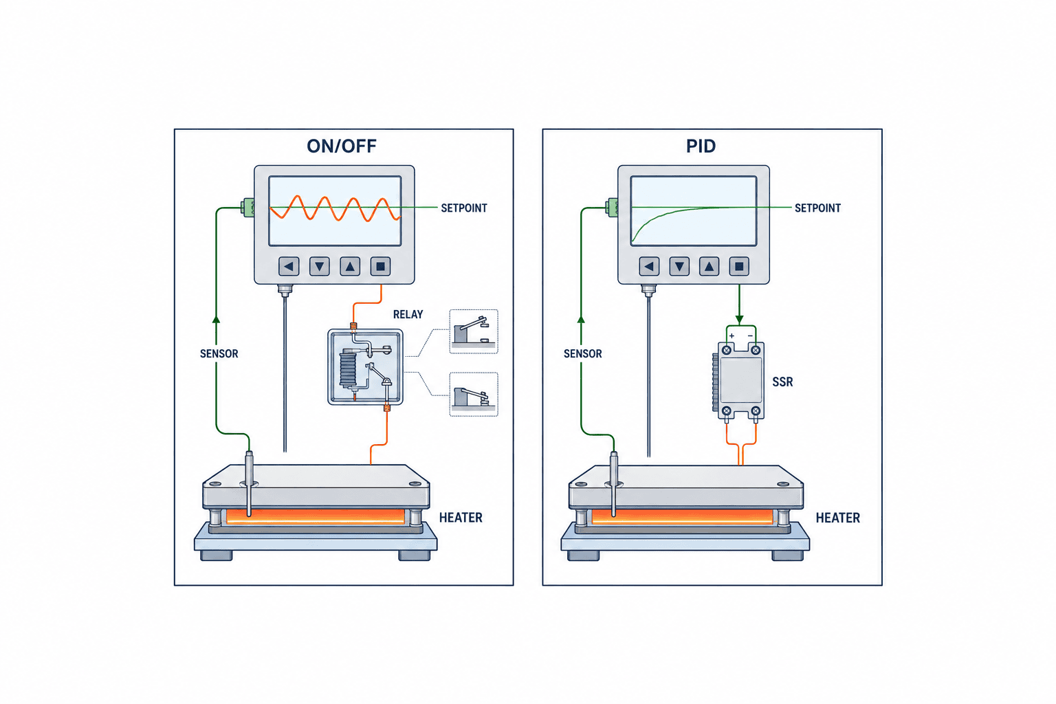
ON/OFF control applies full output or no output in response to the measured temperature. It is straightforward, but a process with thermal inertia can cycle around the setpoint. Check hysteresis and the resulting switching frequency. PID combines proportional action related to error, integral action that addresses accumulated error, and derivative action responding to changes. OMRON’s guide explains the roles of P, I and D. The decision is not whether a catalogue says “PID”; it is whether the process meets its specified temperature band under real loading and disturbances.
ON/OFF may suit a wide tolerance and a load where switching is acceptable. Tighter bands, repeated loading disturbances, or a need to balance warm-up and stable hold can justify PID or separate heating and cooling control. But PID cannot repair a misplaced sensor, inadequate heater, failed SSR or changing product conditions. Record a baseline trend before tuning. Use auto-tuning only under an agreed operating and safety condition; parameters tuned without product are not automatically valid at rated load. Retest after major changes such as a new heater, sensor relocation or product recipe.
The acceptance sheet should name the test point, workpiece, load, ambient condition, trend interval, allowed overshoot, hold band, recovery and reviewer. Otherwise “stable” is a subjective observation. Decide limits from the product and equipment rather than copying a controller brochure. Optional ramp, soak or advanced functions should be included only where the process and operators will actually use them.
Distinguish relay, SSR drive and analogue output
A control output is not necessarily a source of heater power. Relay contacts, a voltage pulse intended to drive an external solid-state relay (SSR), and a linear current output are different interfaces. OMRON’s E5CC-T specifications list these as distinct output variants. The complete part number matters: a family name does not prove that a particular unit has all three.
For relay output, check contact rating against the actual load or contactor coil, expected switching frequency, surge suppression and failure state. Frequent mechanical switching can increase maintenance. For SSR drive, match the controller’s output voltage and current to the SSR input. On the load side, verify the SSR’s voltage and current ratings, heat dissipation, protection and likely failure modes. An SSR can have off-state leakage; the equipment must have an appropriate means of safe isolation. An “SSR voltage output” is a control signal, not direct electrical power to the heater.
For a proportional power controller or valve, an analogue output such as a compatible current signal may be appropriate. Check scaling, broken-wire response, input impedance and auxiliary power at both ends. Put the controller and actuator datasheets side by side in an I/O schedule. Some models offer heater-break or SSR-failure alarms, but these must be verified for the precise model and accessories. One OMRON E5CC variant is an example; do not treat those alarms as standard across the entire family. Define what senses the fault, where its alarm goes and whether the line stops.
Design heater protection separately from routine control
Ordinary temperature control and energy isolation on a fault serve different purposes. If the main controller fails, a probe becomes detached or an SSR remains on, a message on that same controller may provide insufficient protection. Depending on the equipment risk assessment, specify an independent over-temperature limiter, separate sensor, contactor, protective device and manual reset. The exact architecture depends on the hazard and applicable requirements; do not assume one universal circuit.
Test what happens with continuous heater demand, invalid or broken sensor readings, loss and return of panel power, and failed switching devices. Decide whether automatic heating restart is permissible after power returns. Define the operator action after a protective trip so the fault is investigated before reset. Include power distribution, conductor ratings, panel heat, safe maintenance isolation and drawings. Our panel design article covers the wider design and FAT context.
Decide whether a stand-alone controller, PLC or multi-zone system fits
A local panel controller is understandable for a relatively self-contained heating zone. Multiple coordinated zones, recipes, conveyor-speed interaction, long-term records or centralized access control may justify PLC or dedicated multi-loop control. Compare the whole implementation: input modules, cycle time, diagnosis, HMI, programming, commissioning and future maintenance, not just the price of a device.
If a local controller sends data to a PLC, define which system can change SV and whose command takes priority. Specify what happens when communication is lost, how timestamps are reconciled with quality records and which alarms require an operator response. A monitoring platform can aggregate and visualize values, but it does not by itself improve a poorly designed control loop. Our factory-IoT article discusses the move from visibility to action.
Compare exact configurations and full project scope
Compare exact model suffixes and accessories, not catalogue families. The decision table should cover sensor type, range, supply, control mode, output, alarms, communications, mounting, local availability, backups and tests. “Equivalent” is meaningful only when the supplier specifies what is equivalent. A physically similar replacement may have different terminal assignments, alarm polarity, operation and commissioning effort.
| Evaluation item | Required check | Evidence |
|---|---|---|
| Measurement | Sensor, range, wiring and accuracy chain | Installed label, drawings, datasheet |
| Control | ON/OFF or PID, heating/cooling and SV policy | Baseline trend and quality tolerance |
| Output | Relay, SSR drive or analogue compatibility | I/O schedule and actuator specification |
| Alarms | Sensor, overheat and heater faults | Cause/effect matrix and test sheet |
| Integration | Cutout, depth, supply and panel conditions | Panel survey and layout |
| Maintenance | Spare, parameter backup and calibration | Parts list and handover procedure |
| Acceptance | FAT and SAT with pass criteria | Approved test protocol |
Equalize quotation scope: controller, sensor and compensating cable, SSR and heat sink, independent protection, panel work, wiring, software, tuning, FAT, SAT, training and spares. Address taxes, transport and local service as the contract requires. There is no defensible universal controller price or payback figure: an existing panel and production shutdown window can dominate total cost. If the factory still needs to choose which process to automate, our automation consulting guide addresses that earlier decision.
Hidden boundaries in a replacement project
A vendor compatibility table does not necessarily mean the new unit preserves wiring, settings, alarm polarity, contacts and permissions. Old drawings can differ from an altered panel. Trace each terminal to its actual destination before removal, and verify control output, alarms and power separately. Do not copy an unexplained handwritten field modification into a new specification without confirming its purpose.
Define the power-loss and restart state. Some processes may resume with the previous setpoint; others require a human check. A controller left in manual mode can produce an unexpected output when restarted. Record the initial settings, changeover procedure and rollback conditions. Save parameters with their names, units, date, asset and complete controller model, rather than relying only on photos.
List who supplies the controller, changes panel wiring, checks the sensor, approves heater protection and judges production trials. A device seller’s warranty does not automatically cover complete process temperature performance. Assign defect correction and retest responsibility in both the contract and protocol. For comparisons, account for survey, design, downtime, installation, tests, training and maintenance. A cheap unit needing panel machining may cost more to implement. Keep exact part numbers, applicable lines and backup settings in the spare-parts record; visually identical units with different I/O suffixes should not be interchanged.
Align total cost before comparing quotations
Build a common cost sheet for site survey, detailed design, controller and sensor, correct thermocouple compensating cable or RTD wiring, SSR and heat sink, independent protective devices, panel machining, terminals, installation, software changes, tuning, FAT, SAT, training and spares. Ask suppliers to mark each item as included, excluded or an allowance, and state who provides it. Keep duties, tax, freight and local commissioning support explicit where applicable. A quotation for only the controller hardware is not directly comparable with one that includes a safe installed and accepted thermal loop.
Assess the downtime cost and recovery arrangement as well as the purchase price. A low-cost model may require a larger panel opening, new terminals and a longer shutdown. Another may be easier to source locally but require retraining and a new parameter backup process. The right choice depends on the allowed shutdown window, maintenance skills, number of similar machines and target recovery time after failure. Request a fully identified spare unit and a replacement procedure for each I/O variant; do not assume that identical front panels mean interchangeable inventory. Ask how component substitutions will be notified, which datasheet revision governs the purchase and which tests must be repeated after replacement.
Write an RFP that suppliers can answer consistently
Attach process modes, baseline trend, quality band, sensor and heater details, panel photos, electrical drawings, I/O list and fault history. Unknown data should remain explicit survey tasks, not assumed facts. Separate means from outcome: “use PID” names a method; “remain within the agreed band for the rated workpiece and recover after the defined disturbance” names an acceptance result. Specify mandated interfaces where the existing plant requires them, but allow a supplier to propose the control method if it has not been decided.
Require the complete proposed part number, datasheet revision, configured input and output, implemented alarms, protection circuit, panel modification, commissioning, FAT/SAT scope, training, documentation languages, warranty and delivery assumptions. An answer such as “standard function” needs a model-specific reference and test method. In a multilingual plant, maintain a common glossary for SV, PV, alarm, reset and manual mode across purchasing documents, supplier data and local operator instructions.
Use FAT and SAT to prove different things
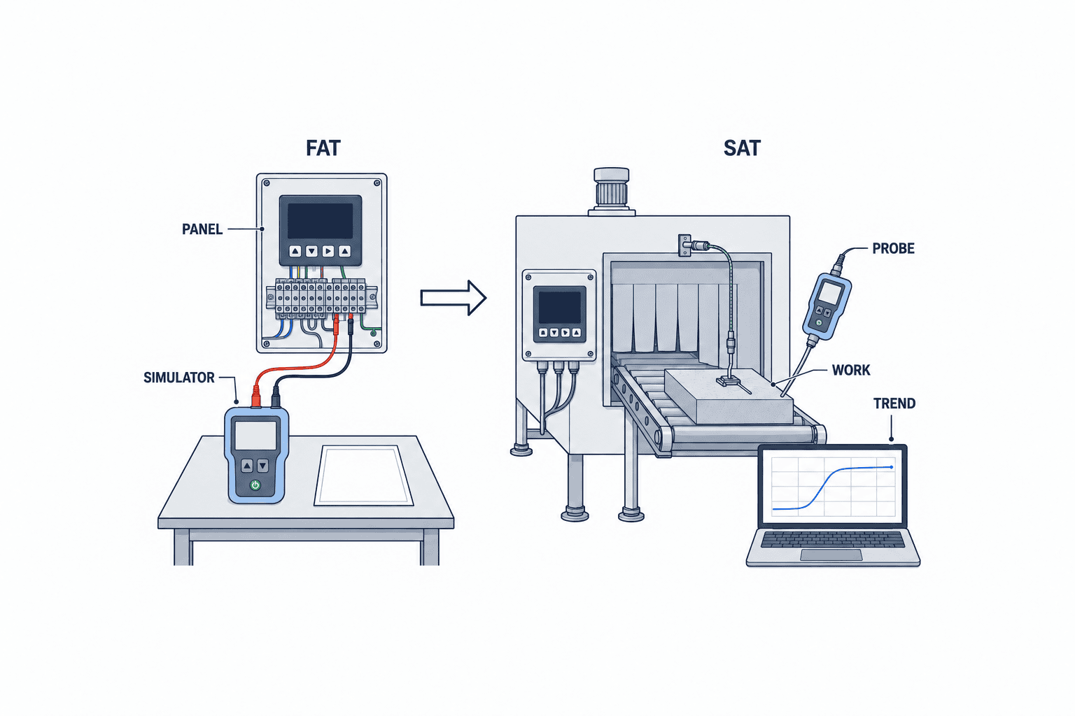
FAT can verify drawings, settings, wiring, simulated sensor values, output terminals, alarm contacts, access rights, power-cycle behaviour and backups before shipping. SAT checks the installed sensor, actual heater, workpiece, ambient conditions and production procedure. Do not sign off real-load performance merely because a simulated FAT passed. Each test record needs its starting condition, expected result, measurement, pass/fail, corrective action and repeat-test evidence. The Eurotherm 3200 user guide is one manufacturer example of the settings, input, control, output and alarm topics that have to be addressed.
At FAT, simulate the agreed thermocouple or RTD inputs safely and verify the displayed values and invalid-input behaviour. Check output and alarm contacts, protections, settings lockout and backup. Remove every temporary bypass and simulation connection after the test and reconcile the as-built drawings. At SAT, trend cold start, rated production, disturbances, recipe changes and restart. When necessary, measure independently near the quality-critical location and compare with PV. Agree in advance on the allowable band, overshoot, settling, recovery and protective response. Do not provoke hazardous faults on a live production line solely to complete a test list; combine safe simulation and wiring verification according to the approved procedure.
Hand over settings, calibration and change control
Diagnose a deviation before changing PID parameters
If temperature starts oscillating after handover, first determine whether it correlates with a product, shift, load, zone or operator action. Compare SV, PV and output trends. A sudden implausible PV change calls for inspection of the sensor, leads, terminals, noise and input setting. If PV falls while the demanded output is already at maximum, inspect heater power, SSR, contactor, supply, insulation and a possible increase in load. If temperature rises after output is commanded off, distinguish residual heat from a switching fault using an approved safe procedure. Corroborate the controller display with an independent instrument, current measurement and quality records. Do not disable an alarm to continue production before identifying the cause.
Preserve acceptance evidence for the next replacement
FAT and SAT records become the benchmark for later maintenance. Keep sensor type and position, workpiece and loading, ambient condition, SV, controller parameters, output period, initial temperature and the identity of test instruments with the trend. A graph without its operating conditions cannot be compared later. When a component or setting changes, assess which acceptance requirements are affected and repeat the relevant tests. Manage drawings, bill of materials, parameter backups and test sheets as one revision-controlled set.
Decide which roles may change SV and which may alter sensor type, output mode, alarms or PID parameters. An incorrect sensor selection can display a plausible but wrong temperature. Deliver a settings list, change log, backup and restoration procedure. Similar-looking controllers on different lines may need different parameters, so bind each backup to an asset and full part number.
Calibration should address the measurement chain that represents quality, not only the display. Define reference instrument, test points, stabilization, location, tolerance and action on failure. After replacing a sensor, investigate an unexpected offset before using a correction value to hide it. Keep replacement and temperature records so the quality team can assess the possible impact of an out-of-tolerance finding. Adjust intervals based on process criticality, environment and failure history.
The initial SAT cannot cover every season, product and load. Name the untested conditions and monitor temperature excursions, heater replacements, manual interventions, alarms and parameter changes during early operation. If performance drifts, revisit sensor position, insulation, heater distribution and loading variation as well as the controller settings.
FAQ: industrial temperature controller selection
Can I replace a controller with one that has the same front dimensions?
Only after checking sensor input, output, supply, terminals, depth, alarms and interfaces against the actual installation. Match the full model suffix and plan wiring changes and acceptance tests.
Will PID eliminate temperature variation?
Not necessarily. A misplaced sensor, insufficient heater, failed SSR or changing load can dominate the response. Record the baseline trend and diagnose the process before tuning or replacing the controller.
Should I use a thermocouple or Pt100?
Decide from process range, accuracy, environment, response, wiring and maintenance. Match the controller input to the exact sensor. Use suitable compensating cable for thermocouples and verify RTD wiring and lead resistance.
Can I connect a heater directly to an SSR-drive output?
No. An output specified to drive an SSR is a control signal for the SSR input, not heater power. Design the external switching device, heat dissipation, supply and protective circuit separately against the exact datasheets.
Why specify both FAT and SAT?
FAT verifies what can safely be simulated and inspected before shipment. SAT verifies performance with the actual equipment and production load. Assign each acceptance requirement to the stage that can prove it.
What information must I give a supplier to obtain a useful quotation?
Provide the target machine and process, complete installed controller model, actual sensor type and wiring, heater and switching-device details, supply voltage, panel drawings and photographs, temperature acceptance band, baseline trend, required alarms and independent protection, available production shutdown time, and proposed FAT/SAT conditions. Identify unknowns as a separate site-survey task rather than filling them with assumptions. Ask the supplier to state exclusions and the evidence it will use to demonstrate each proposed replacement function.
Conclusion
Select an industrial temperature controller by defining the process band, measuring the existing response, confirming the sensor and actuator interfaces, designing protection, and then agreeing on an RFP and acceptance tests. This sequence makes supplier quotations comparable and gives the factory evidence that the installed thermal loop meets quality and safety needs. If you are preparing a replacement or new thermal process in Thailand, TOMAS TECH can discuss the survey and RFP stage before a controller model has been chosen.


