



Air blow nozzle selection starts with the result on the workpiece, not the highest velocity or a savings percentage in a catalogue. Removing chips from a recess, pushing water off a flat surface and drying a moving package require different airflow patterns. Nozzle performance also depends on distance, angle, pressure at the point of use, blow duration and where debris goes. This guide helps a Thai factory define its baseline, compare alternatives, write an RFP and verify the result at FAT and SAT.
Treat the blow-off task as a process requirement
Record the workpiece material and dimensions, contaminants or liquid, conveyor direction, cycle time, allowable residue and downstream process. For cleaning, define an observable outcome such as no chips on a specified surface under a stated inspection method. For drying, identify which droplets would harm the next step. Add limits for deformation, scratching, redeposition, noise, liquid spray and dust. A strong jet can pass a simple visual test while creating a new problem on the adjacent product or workstation.
Draw the full air path from the regulator through the valve, hose, fittings and nozzle. Measure pressure close to the nozzle while air is flowing, as well as at rest. A compressor-room pressure display cannot show every point-of-use pressure loss. The US Department of Energy’s compressed-air sourcebook recommends examining the air quality, quantity and pressure needed at the end use. It also flags open, unregulated blowing as a potentially inefficient use. Before purchasing a different nozzle, ask whether a brush, extraction or low-pressure blower can meet the same workpiece requirement.
Agree on the inspection method before testing suppliers. A reference photograph, repeatable vision test, absorbent paper or mass difference may be appropriate depending on the process. Set acceptance values from the product specification, not a universal number from a blog. Test what happens to the expelled material: chips should not redeposit and droplets should not reach electrical equipment. Acceptance is the workpiece outcome plus the surrounding effects.
Establish a baseline for a fair air nozzle comparison
Capture at least five classes of evidence: before-and-after workpiece condition, flowing pressure at the nozzle, compressed-air flow, actual valve ON duration and noise at a defined worker location. Record the number of nozzles running simultaneously and whether the line is producing, waiting or stopped. A hand gun needs observed trigger time; an automated station needs PLC signal timing alongside flow or pressure. The valve may close after the command changes, and air stored in a long hose may continue to discharge.
Supplier noise, force and consumption figures are useful only with their test conditions. EXAIR’s nozzle catalogue, for example, states an 80 PSIG (about 5.5 bar) supply for its comparison table; sound is measured about 914 mm away and force generally about 305 mm from the target. A different distance or pressure can make a table appear to show a product advantage that does not exist at your line. Measure the installed system at the operator’s position and during concurrent production.
| Evidence | Hold constant during comparison | Acceptance record |
|---|---|---|
| Workpiece | Material, contaminant, speed, inspection | Images and pass/fail results |
| Air | Flowing pressure, simultaneous demand, air quality | Pressure and flow logs |
| Installation | Distance, angle, height, guarding | Dimensioned drawing and photographs |
| Control | ON time, cycle count, idle shutoff | PLC and cycle records |
| Surroundings | Noise position, spray path, operator location | Noise and containment checks |
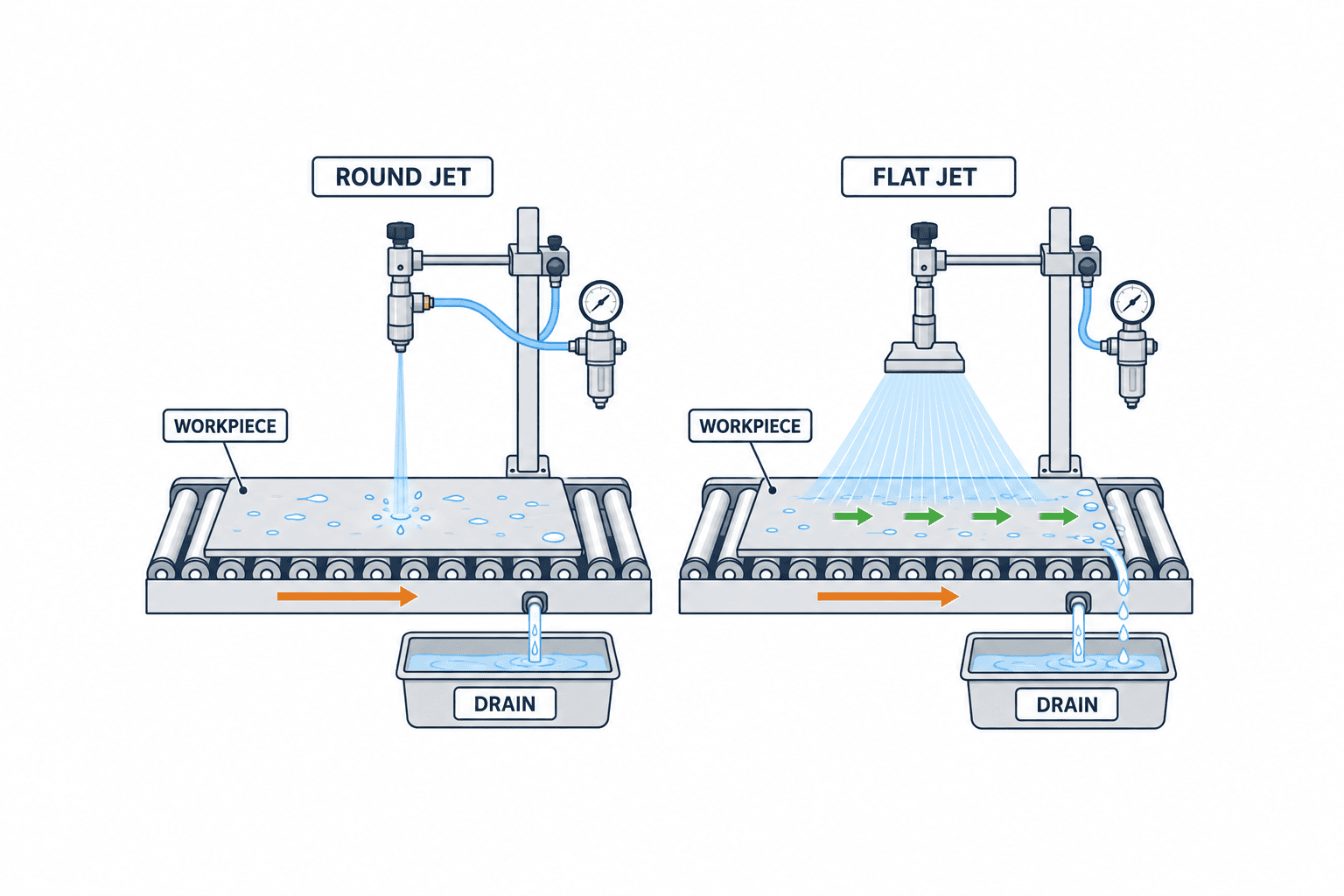
Match the nozzle shape to the target
A round, concentrated jet can reach a local chip or recess. One such nozzle may not cover a broad surface without traversing or adding more nozzles. A flat pattern can cover a strip, although edge coverage and angle may leave water behind. An air knife or low-pressure blower may suit a large continuous surface. Compare the width that must be treated, delivered force at the actual stand-off, air demand, mounting space and how the material leaves the station. Product names alone do not decide the result.
An air-amplifying nozzle entrains surrounding air. Do not confuse the total moving airstream with the volume of compressed air drawn from the header. Product tables can narrow the candidates, but a guarded enclosure, long hose and varying workpiece height change the outcome. Check the minimum and maximum nozzle-to-workpiece distance and the allowable angle deviation. Provide a fixture that can be returned to its accepted position after maintenance.
For drying, design a place for the liquid to go. Blowing it from the top face onto a side face is not a completed drying process. Consider gravity, recesses, conveyor orientation, drainage and extraction. For chip removal, provide a capture path so removed chips do not circulate back into the product. Otherwise the apparent solution is often to add still more air.
Materials and maintenance matter. Check chemical compatibility near cleaning agents, the possibility of product contact, damaged protrusions and replacement access. Processes involving food or medicines need the air-quality and hygiene requirements of that specific process. Water, oil or particles in the supply can contaminate the workpiece and impair the nozzle or valve. For the upstream issues, see our articles on compressed-air dew point monitoring and compressed-air leak detection.
Calculate compressed-air blow-off savings without overstating them
Compare baseline and proposed compressed-air consumption at the same throughput and accepted product quality. At a station, flowing consumption multiplied by actual ON time and cycle count is a useful starting estimate. State whether the meter reports a standard or actual volume and keep units and reference conditions consistent. If a nozzle needs a second pass to clean the part, count both passes. If a short pulse achieves the same quality, include valve response and any tail flow after the command ends.
An SMC product page and its IBG catalogue show an 87% reduction in air consumption and 97% shorter operation in the manufacturer’s specified comparison for its hand-held impact blow gun. Those figures describe that hand-held product and test arrangement. They are not a general result for fixed nozzles or a forecast for your factory. Confirm the comparator, supply pressure and footnotes, then run a trial on your own workpieces.
The DOE’s end-use efficiency tip sheet advises reviewing required end-use pressure, asking suppliers for exact air demand and reconsidering inefficient open blowing. Do not lower a plant-wide pressure setpoint solely because one nozzle changes; first check every critical pneumatic user. Likewise, reduced air use is not automatically the same percentage reduction in compressor electricity. Compressor controls, other loads and operating hours affect the electrical result. Use the plant’s actual tariff and measured compressor operating data for a financial case.
Combine nozzle design with ON/OFF control
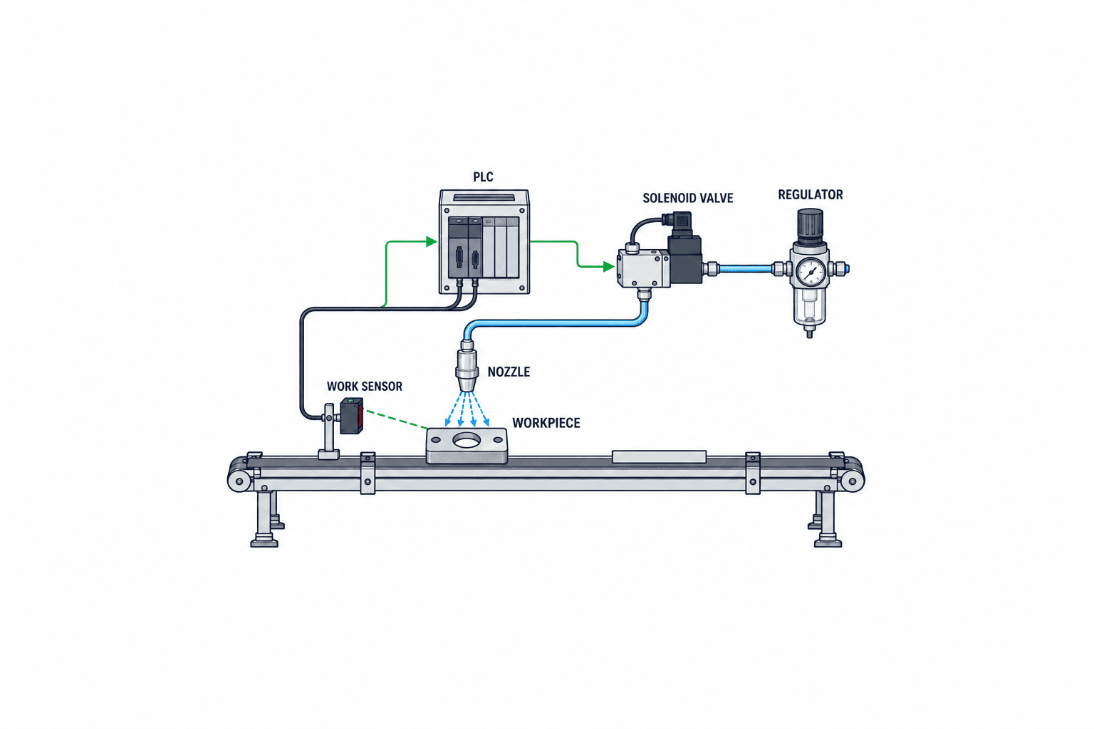
A presence sensor can trigger the valve as a part arrives and shut it after the trailing edge passes. Confirm sensor location, PLC delay, valve response, hose volume and real airflow start and stop. Test product changes, line pauses and emergency stops. Where pulsing is useful, determine the shortest duty cycle that still meets the workpiece criterion. A valve left open during idle time can defeat the advantage of an efficient nozzle.
When reusing a valve, check its flow capacity, pressure range, electrical supply, seals, response and exhaust arrangement. Our pneumatic solenoid valve selection guide covers valve-level decisions. Here the acceptance question is whether the valve and nozzle together deliver the required flow at the required time.
Manage spray, chips and noise as part of cleaning and drying
A part may look clean while chips are propelled towards an operator or another product. Inspect the actual trajectory, guard openings, extraction inlet and worker positions. Hand-held guns need a defined working method; do not design around directing air at skin or clothing. Assess the machine against applicable Thai law, site rules and customer requirements, and specify guards and personal protective equipment accordingly.
As a reference from another jurisdiction, US OSHA rule 29 CFR 1910.242(b) addresses compressed air used for cleaning, requiring pressure reduced below 30 psi together with effective chip guarding and personal protective equipment. This is a US rule, not a statement of Thai legal requirements. Nor does a low pressure remove the need to consider flying material and bystanders.
Drying can redirect liquid toward electrical cabinets, sensors or floors. A chemical or food-related residue may need capture and disposal. If dust cannot be contained, extraction or another process may be preferable. The DOE’s inappropriate-use tip sheet identifies alternatives for some cleaning, drying and cooling duties, including low-pressure blowers, fans, brushes and appropriate nozzles. Select among them using the workpiece result and local hygiene and safety requirements.
Measure noise with the actual part and its reflecting surfaces, at the locations where people work, with other equipment running. A catalogue sound level measured in free space is not the station sound level. Preserve the distance, supply pressure and test arrangement next to each supplier’s quoted number.
Write an RFP that allows suppliers to quote the same task
Supply a workpiece drawing or safe-to-share photograph, defect examples, contaminant type, conveyor speed, allowable residue, current pressure and flow, ON time, air quality, guard geometry and available installation space. Mark information that requires a site survey instead of silently asking the supplier to guess. Ask each bidder to describe the proposed nozzle and material, required supply pressure and flow with reference conditions, pattern width and reach, fixture, regulator, valve, sensor, hose, guarding, capture path, spares and maintenance.
The scope should also say who connects to the existing machine, modifies PLC logic, supplies power, arranges a shutdown and manages quality during commissioning. Price the entire installed solution: piping, controls, trial workpieces, verification, spares and downtime as well as the nozzle. Keep compressed-air savings and labour or rework changes as separate estimates. If an energy saving is stated in money, record its measured inputs and calculation.
| RFP section | Supplier deliverable | Buyer verification |
|---|---|---|
| Workpiece quality | Before/after test on shared samples | Common inspection method |
| Air demand | Flow, ON time, cycles, simultaneous nozzles | Meter and PLC records |
| Installation | Distance, angle, fixture, replacement access | Drawing and site check |
| Safety | Spray and chip containment, noise | Risk assessment and trial |
| Controls | Sensor, valve, stop and fault behaviour | FAT and SAT |
| Maintenance | Cleaning, clogging, spare parts | Procedure and handover |
Screen products first at the same supply condition, then optimise each candidate to the lowest pressure and duration that still pass the quality criterion. This separates performance margin from efficient running. Test ordinary and challenging parts, not only pristine samples. Record meter position, calibration, volume reference condition, noise position and who made the quality decision. If a supplier’s flow, force or noise figures lack conditions, request them before calling the data comparable.
An example comparison test sheet
Give each trial a row for part number, production lot, contamination before treatment, line speed, air supply, candidate nozzle, stand-off, angle, valve ON duration, flowing pressure, flow, ambient conditions and inspector. A warm part fresh from a mould may carry liquid differently from a part left to stand. Chip material, length, oil film and location also affect removal. A single convenient sample can miss the product variant that causes the real complaint.
Keep the trial sequence fair. Testing candidate A during low air demand in the morning and candidate B during a high-demand period can make a header-pressure change look like a nozzle advantage. Alternate candidates in the same period where practical; otherwise attach pressure and line-load histories. A short demonstration cannot establish resistance to clogging or position drift in a long-running process. Inspect the nozzle, condensation and fixture after the trial to confirm that test conditions remained intact.
Check the flow meter’s range and response. A slow instrument may miss the peak of a short pulse; an accumulated volume, suitable meter or longer observation window may be needed. Measure pressure close to the nozzle with sufficient response to reveal a transient drop. If a value must be estimated, label the estimate, equation and uncertainty. Record where residues remain, not only the overall pass rate: wet edges may suggest pattern or angle, while chips in a recess may indicate direction or a missing capture path. If inspectors disagree, revise the photographic standard with the quality team.
Turn an air-cost estimate into an auditable contract assumption
Provide separate inputs for baseline and candidate flowing air rates, actual blow time, parts per hour, operating hours, days and the plant’s electricity tariff. Where the meter reports standard volume, use the same reference state for both candidates. A simple station estimate is annual air use V = Q × t × n, where Q is flowing demand in standard m³/min, t is real minutes of blowing per cycle and n is cycles per year; V is standard m³/year. Calculate baseline minus candidate in the same units. If the plant has a measured compressed-air unit cost C in THB/standard m³ for that operating period, estimated annual air-cost difference is ΔV × C in THB/year. Leave the currency result open when C is unavailable; do not import another factory’s rate or a catalogue’s annual saving.
Count tail flow after the valve command, repeat blows and rejected parts consistently. Reduced air demand at one nozzle does not always create the same percentage change in compressor electricity. Control mode, unload periods, receivers and other users matter. Report measured station air reduction and measured supply-side electricity reduction in separate columns, normalized to production. For a guaranteed saving, agree on measurement boundaries and how changes in production mix and operating conditions are handled.
Quality and safety are mandatory gates before an efficiency score. A low-flow candidate that causes a second cleaning step may cost more overall. Include spares, replacement time and local availability in the installed-cost comparison. State how a supplier will verify any promised saving rather than treating a product brochure as the contract method.
Site checks that prevent procurement rework
Measure the real installation envelope. A nozzle that fits a drawing may collide with a cable carrier, robot movement or changeover fixture. Confirm that a technician can open the guard and reach the fitting with tools, that the pipe can be fixed securely and that the installed direction can be restored after servicing. Agree on shutdown windows, electrical and pneumatic isolation points and restart checks before modifying the machine. Return every accepted field change to the drawing.
Check whether extraction can handle added chips or mist. A stronger jet may oppose extraction or form a vortex inside a guard. Test whether water or dust reaches a nearby inspection camera or photoelectric sensor; the blow-off station can improve while the whole line experiences more stops. Tell the owners of neighbouring equipment what the trial may affect. Include spare stock, replacement lead time, discontinuation alternatives and the retest needed for substitute parts. Check whether modification affects the original machine warranty.
If the existing air supply cannot support several nozzles at once, ask bidders to show a separate response. A trial with other machines stopped is not a test of simultaneous production. Alternatives may include staggering blow times, reducing the number of nozzles or correcting pipe losses. Raising the entire plant setpoint requires a check of other pneumatic users and equipment limits. Mark unknown RFP values as “confirm at site trial” and assign the person and method for deciding them.
Verify selection at FAT and SAT
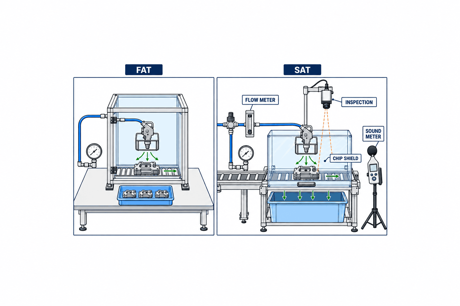
At FAT, inspect the bill of materials, drawings, sensor and valve logic, stop behaviour, guards, fixture and replacement method. If representative parts are available, test the stated contaminant, speed, stand-off and quality method. Check whether air continues after the PLC command is OFF because of a valve fault or stored pressure. A successful FAT does not replace the on-site trial.
At SAT, repeat the workpiece test with the factory’s pressure variation, other machines running, product changeovers and the actual operator position. Log flowing consumption and ON time as well as quality. Check chip or liquid capture, noise, line stop behaviour and loosened fittings. Compare with the baseline at comparable throughput and conditions. If conditions differ, report the difference rather than attributing every change to the nozzle.
Judge quality, safety, cycle time, air use and maintainability separately against the RFP. If the product fails, merely increasing pressure may increase spray, noise and cost. Try angle, distance, extraction, nozzle count or timing, then agree on a controlled retest. Save photographs and logs so future drift can be distinguished from the accepted installation.
Keep the accepted setting in daily operation
Check direction, stand-off, physical damage, blockage, drain and filter condition and unusual noise during routine inspection. Document why a pressure setting was selected and who may change it. When cleaning performance drops, examine workpiece changes, incoming contamination, conveyor position, pressure loss, valve response and blocked passages before replacing the nozzle. Retest a reference part after replacing a nozzle and update the part number, setting and image.
Track accepted quality, rework, compressed-air volume, valve ON time, noise and maintenance effort separately. Monthly electricity cost alone is affected by output, other compressor loads and tariffs. If the change does not produce the intended outcome, reconsider the process requirement and alternatives before adding more pressure.
Make the Thai-factory handover measurable
In a multilingual plant, a drawing number, PLC tag, maintenance instruction and spare-part number must identify the same physical nozzle. Use an annotated site photograph and state which settings may be adjusted and which are fixed. Distinguish a compressor-room pressure reading from the pressure measured at the nozzle; state units and meter position. Give operators a short daily checklist and maintenance staff a more detailed fault-isolation procedure.
Keep reference photographs of normal parts and difficult variants, including lots with many chips or water that tends to remain. One SAT cannot cover every season or material lot, so define a follow-up period where justified. Recheck quality, air use, clogging and alignment. A datum face or fixture that restores stand-off and angle after a nozzle is removed makes the accepted setup reproducible.
Record the reason for each adjustment, old and new pressure, position and ON time, the part tested, the quality result and the approver. This reveals when a temporary pressure increase quietly becomes the permanent setting. Decide whether “fail” means any visible particle, residue in a specified zone or a defect confirmed downstream; provide several images at the boundary and agree with quality and production before trial. Keep the sample-selection method constant.
For multiple shifts, distinguish start-up, continuous running and post-changeover checks. Humidity or material changes may alter drying, so list unobserved conditions for a later check. Passing SAT on one day is not a promise of identical performance for every future season. Define who cleans a blocked nozzle, diagnoses a valve, judges the part and reviews air trends, with an escalation order. Preserve the accepted images, logs and meter positions where the next maintenance team can find them.
Frequently asked questions
What should an air blow nozzle comparison start with?
Define the cleaning or drying outcome, actual distance, point-of-use pressure and installation limits. Then compare pattern, air consumption, force, noise, material and maintenance under stated test conditions.
Can a catalogue percentage establish compressed-air savings?
It can motivate a trial, but cannot certify a factory result. Measure baseline and candidate flow and ON time at equal product quality and throughput. Check compressor operation before turning an air-volume reduction into an electricity saving.
Is a round or flat nozzle better for cleaning and drying?
A concentrated round jet is a candidate for a local chip or recess; a flat pattern can suit a wider wet strip. Workpiece geometry, distance, speed and a path for the removed liquid determine the result. Include air knives or low-pressure blowers for a broad continuous surface.
What belongs in the RFP, FAT and SAT?
The RFP defines the part, contaminant, acceptance method, air and installation conditions and safety. FAT checks hardware and logic; SAT checks installed quality, consumption, noise, containment and maintenance. Agree on numerical acceptance criteria from the actual process before purchase.
Does the US OSHA 30 psi rule apply to a Thai factory?
It is a US cleaning rule and should not be represented as Thai law. Check applicable Thai requirements and the factory’s risk assessment. Flying material, guards, PPE and nearby people still require attention.
Conclusion
Choose a nozzle by its repeatable result on the specified workpiece and by the ability to manage air use, noise and flying material. Measure the baseline, compare pattern and point-of-use conditions, specify valve timing and capture, and write test conditions into the RFP. FAT verifies the proposed assembly; SAT verifies the working factory line. Catalogue figures help shortlist products, while acceptance rests on your own process evidence.
If you are comparing nozzles or preparing an RFP and FAT/SAT plan for a Thai factory, contact TOMAS TECH. A discussion can start from workpiece photographs and an incomplete piping sketch while the remaining measurements are planned.


