


Photoelectric sensor selection starts with a detection event, not the longest range in a catalogue. A clear bottle, polished metal part, black moulding and changing package colour each alter the light reaching a receiver. For production engineers, maintenance teams and buyers in Thai factories, this guide turns those differences into a purchase specification: select the sensing geometry, test real workpieces, match the PLC input, compare complete installed cost, and verify the result at FAT and SAT.
This is a general engineering guide. Performance depends on the model, setting and installation. An ordinary object-detection photoelectric sensor is not a personnel-protection device. Omron’s safety precautions expressly separate these sensors from protective devices for presses and similar hazards. Design machine safety with the appropriate safety-rated equipment and requirements.
Define the event before choosing a photoelectric sensor
A photoelectric sensor converts a change in received light into an electrical output. The light is blocked by a target or reflected from it. Omron’s technical overview describes through-beam, retroreflective and diffuse-reflective arrangements. These names are useful, but a procurement request must state both what shall trigger the output and what shall not.
Write, for example: “Count a clear bottle once when it crosses this point, whether it is empty, full or differently labelled.” Or: “Permit dispensing only when the black plastic component is fully seated, while ignoring the stainless fixture behind it.” Those statements identify the target, background, mounting position and control consequence. “Detect part present” leaves too much open to interpretation.
Record material, colour, transparency, surface finish, minimum dimension, position tolerance, speed, vibration, mounting distance, background, ambient light, oil, dust, water, cleaning process and PLC input. For a product family, keep both the hardest genuine target and the object most likely to cause a false positive. Drawings can narrow the candidate list, but physical samples must be part of acceptance.
Pair positive and negative test cases
For bottles, compare empty and filled items, labels, condensation and reflections from conveyor rails. For seating, compare correct placement, a lifted part, a tilted part, a similar but wrong part and the empty jig. A part may briefly clip a beam, so define whether the PLC accepts any transition or requires the signal to remain stable. Sensor response time, input filtering and travel speed all affect the answer.
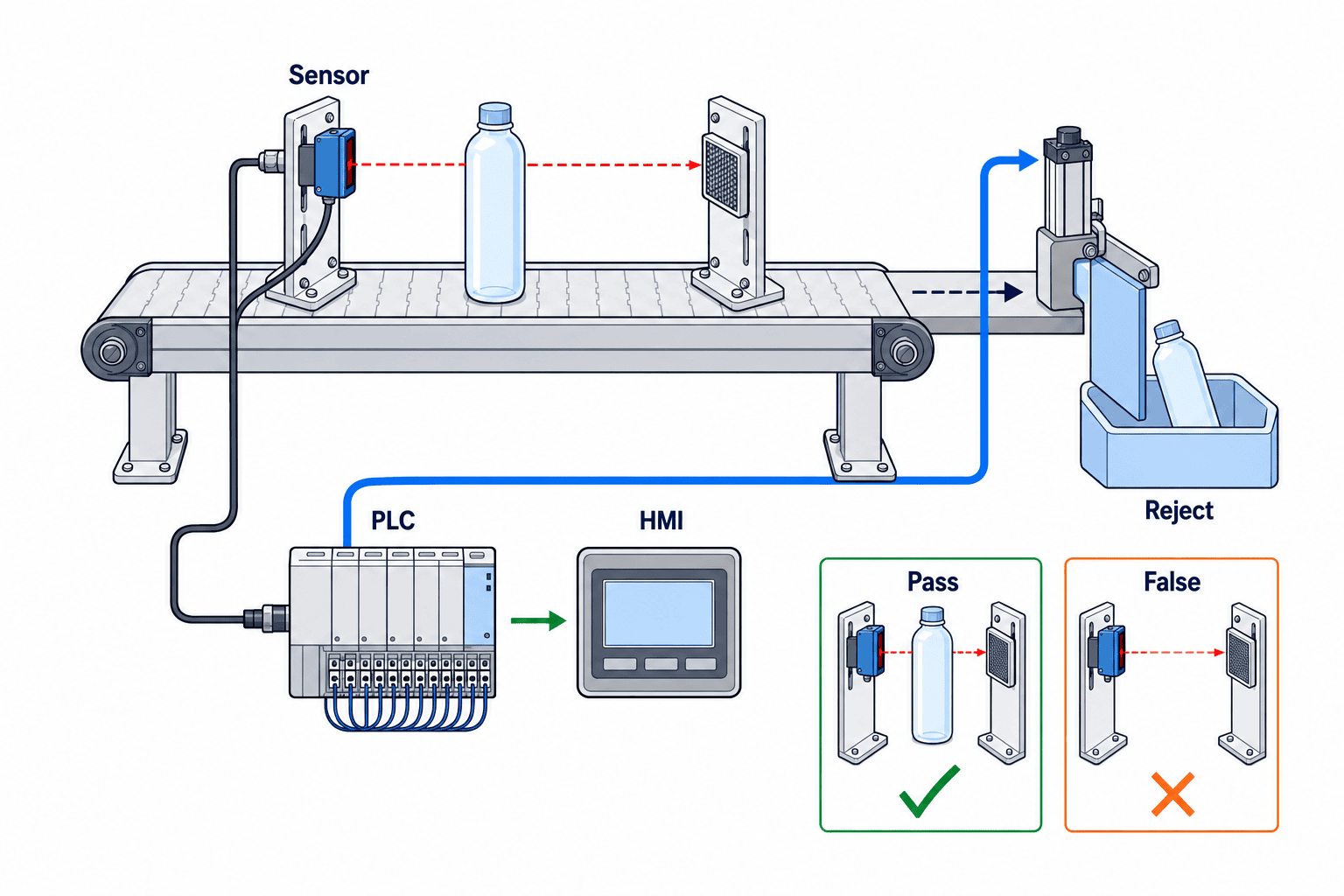
Define the normal state of the input too. Light-ON and Dark-ON are different output choices, as Omron’s terminology guide explains. Show the expected sensor output, PLC bit, HMI message and fault response in one state table. Do not infer a safety function merely from an ON/OFF logic choice.
Choose through-beam, retroreflective or diffuse by mounting geometry
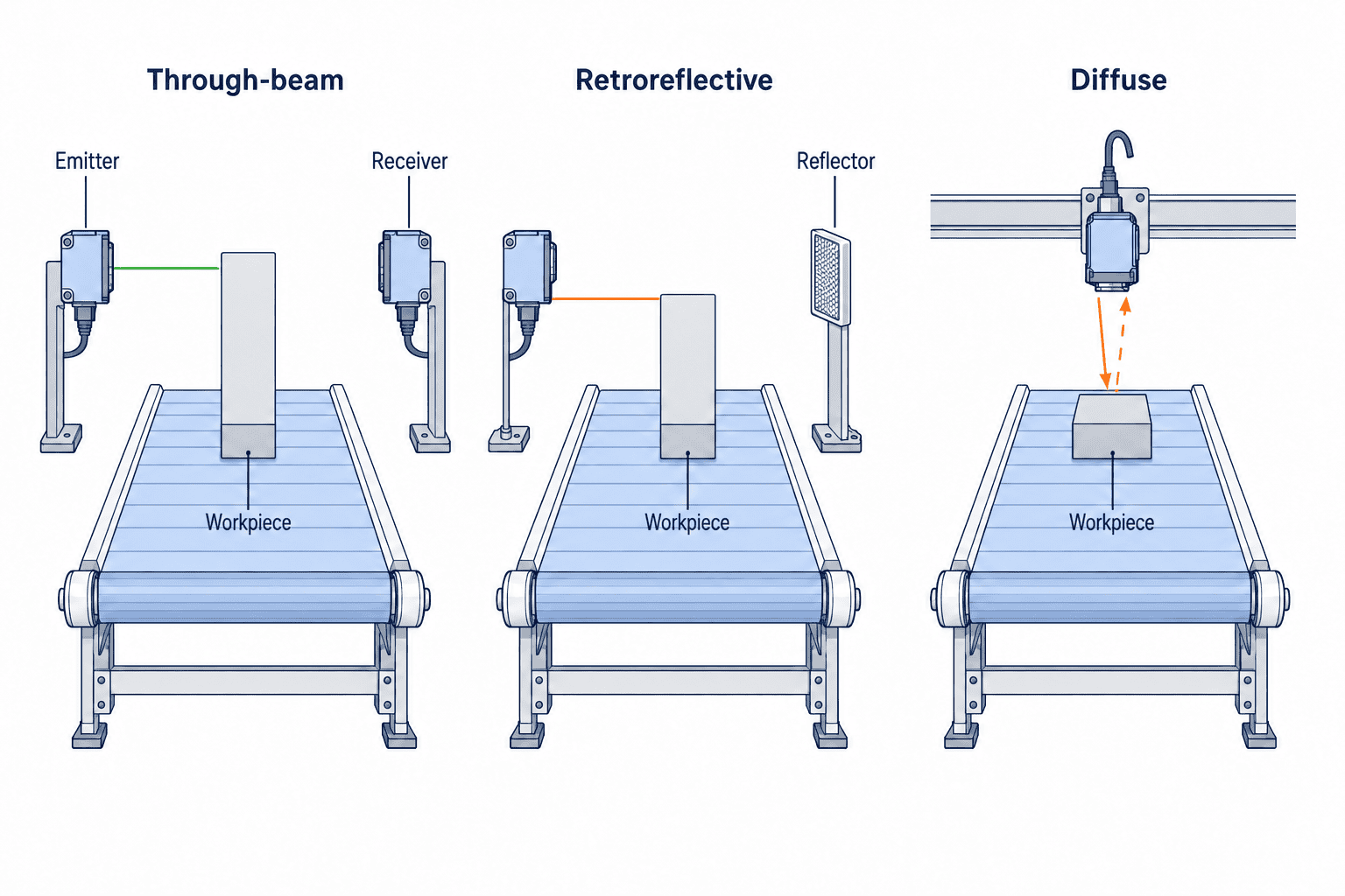
First ask whether equipment can be installed on both sides of the path. If so, through-beam is a candidate: a separate transmitter faces a receiver and an opaque target interrupts the beam. Target colour and surface reflectivity often matter less, but mounting, wiring and alignment are needed at both sides. A transparent target may pass enough light to remain invisible, and a tiny target may miss the optical path. Banner’s sensor selection guide favours opposed sensing for opaque targets while requiring sufficient sensing contrast and excess gain.
If wiring on the far side is difficult but a reflector fits, assess retroreflective sensing. Transmitter and receiver share a housing; a target changes the return path from the reflector. A shiny target may return light much like the reflector, and a clear target may attenuate too little. Polarised or clear-object models are candidates, subject to sample testing. Include reflector contamination, movement and water after washdown.
If only the target side is accessible, diffuse reflection may fit a short-range task. It relies on light returned by the workpiece, so dark colour, gloss, distance and angle matter. Where a bright rail or metal plate sits behind the target, add a background-suppression or distance-settable candidate. ifm’s application selector includes background-suppression choices among the modes matched to applications. The term is not a promise to reject every background; test the actual depth variation.
| Mode | Installation need | Useful starting case | Failure to test |
|---|---|---|---|
| Through-beam | Two mounts, two-sided wiring, aligned axis | Opaque objects crossing a conveyor | Clear targets and small parts missing the beam |
| Retroreflective | Reflector and clean return path | One-sided wiring | Mirror-like targets, clear targets, dirty reflector |
| Diffuse | Target-reflected light | Short-range one-sided presence | Dark, glossy or tilted targets; bright background |
| Background suppression | Target/background distance difference | One-sided detection near a background | Height and background-position variation |
The table narrows a shortlist rather than deciding the model. ifm’s application selector can help create that shortlist; your parts and machine decide acceptance.
Test clear, reflective and dark targets separately
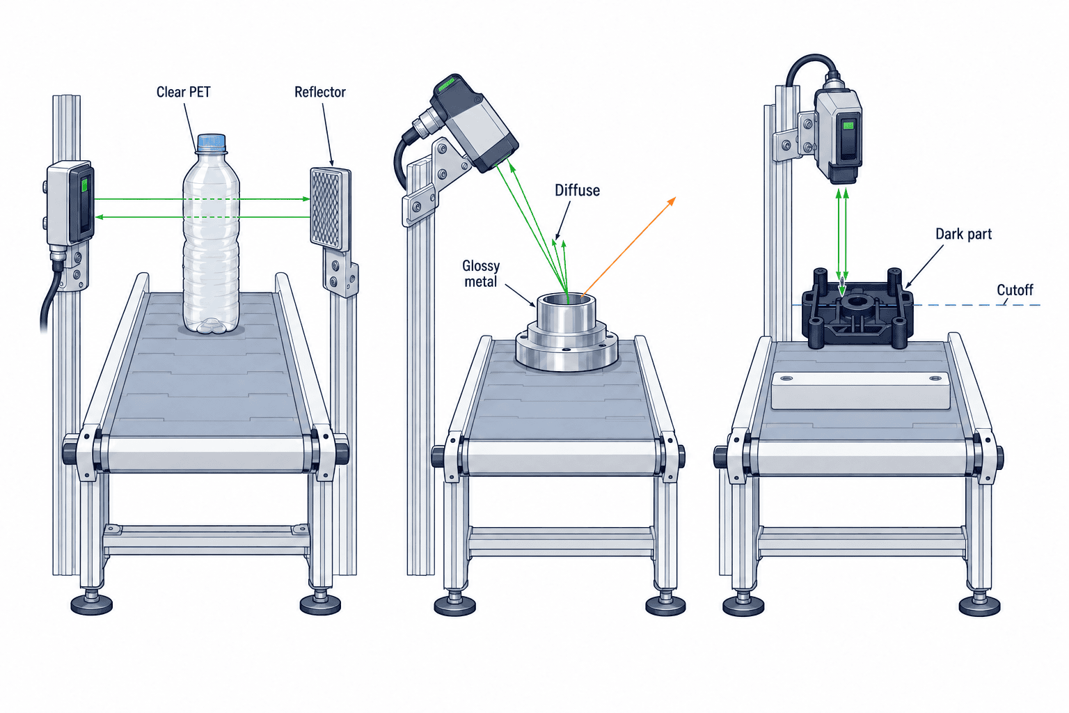
A clear PET bottle or film may create only a small change in received light. Orientation, mould marks, condensation, liquid level and labels can change that signal. Banner’s clear-object guide recommends selecting the detection approach for the material and application. KEYENCE’s sensor guidance gives an example in which the target’s entry direction relative to the optical axis affects clear-object detection. Test at the actual travel height and angle, not merely somewhere between sensor and reflector.
Polished metal and metallised film pose a different problem: the direction of specular reflection. A modest tilt can turn a strong return into a weak one. Compare through-beam, polarised retroreflective and distance-based candidates. Include maximum and minimum normal tilt, scratches, oil film and production lighting. If a deliberately angled sensor is required, document the mounting datum. “It works at today’s angle” is not a maintainable specification.
Black mouldings often return less light than the white reference target used in a diffuse sensor’s rating. Omron’s distance definitions explain the role of the standard sensing object. Test production lots across colour, finish, angle and distance. Record received-light indication or operating reserve at the real mounting position. If a beam can be interrupted instead of relying on the target surface, compare that option.
Size, spot and slit are separate from range
A stated sensing distance does not establish that a narrow pin or film edge is detectable. A broad beam may still reach the receiver when the small object crosses it. Omron’s technical guide treats minimum detectable object, sensitivity setting and use of slits as distinct conditions. A slit may help with small targets but reduces received energy, so evaluate contamination reserve at the same time. Test warped and tilted parts and the full positional tolerance, not only the smallest ideal sample.
Match optical timing to the control cycle
Catalogue ranges use different reference targets, reflectors and settings. Compare candidates at the same real mounting distance, with the same workpiece and the reflector or accessory included in the quote. Record model, setting, received-light reading, allowed alignment error, response time, supply and output.
A faster conveyor shortens the time for which a target interrupts the optical path. Effective blocking width divided by travel speed gives an initial duration estimate, but acceptance must include sensor response, PLC input filter, scan cycle and count logic. Test close-spaced consecutive items, a stopped item, reverse travel and overlapping items. If counting is the purpose, decide whether a rising edge is one count and how jams are handled. If seating confirmation is the purpose, decide whether to require a stable interval before dispensing. Our PLC basics article covers the controller; the present article specifies the physical input it must trust.
Mounting brackets move with vibration and maintenance. Check the least favourable position within mechanical tolerance, not just a nominal catalogue range. Record photos, datum dimensions and a replacement alignment method. A spare sensor of the same model does not restore production quickly if no one can reproduce the optical axis.
Allow for dirt, water and interfering light
Dust, oil, wash water and condensation alter the received signal after commissioning. Excess gain describes received optical energy relative to the switching threshold. Banner’s explanation gives environmental guidance, but its numerical examples are general guidance for Banner applications, not universal guarantees. Consult the selected model’s excess-gain curve at the real distance and record the condition before and after cleaning.
An enclosure IP rating is different from optical performance with droplets on the lens. Omron’s water-exposure FAQ notes that water on a lens can cause erroneous operation even for an IP67 product. For washdown, specify spray direction, chemicals, wiping material and cleaning interval. Assess lens and housing compatibility separately where oil is present.
Test daytime and night lighting, open machine guards, neighbouring transmitters and strong task lights. Multiple nearby sensors can interfere if one beam reaches another receiver. Even where a model offers interference prevention, test the actual number, spacing and directions. Document baffles and beam angles so a later sensor addition does not disturb the existing line.
Match PNP/NPN output and PLC input before ordering
Optical performance alone does not make a usable installation. Specify supply voltage, current, PNP/NPN or other output type, load, Light-ON/Dark-ON, connector and cable length. SICK’s product range and ifm’s selection material illustrate that electrical and connection variants accompany optical choices. For a Japanese-built machine modified in Thailand, inspect the actual PLC input common and local spare-parts stock.
PNP and NPN are not rankings of quality. The correct choice is the one compatible with the PLC input circuit and supply design. Compare terminal diagram, input ON condition and full model suffix. During commissioning, inspect both the electrical signal and PLC monitor. Wire colour alone is insufficient; use the wiring diagram for the exact model. Keep the same part number in quotation, drawing and spare-parts list.
Cable routing must account for moving bends, oil, chemicals, washdown, noise sources and connector sealing. Document the initial sensitivity setting, who may alter it and how changes are recorded. IO-Link or another diagnostic interface may expose received light and parameters, but specify who monitors the data and what change triggers cleaning or replacement. Data collection without an action owner adds little value.
A single digital OFF state can mean no workpiece, cable break, power loss, dirt or misalignment. Decide how the process distinguishes or responds to these conditions. This concerns ordinary process and quality control; personnel protection requires a separately designed safety system.
Use a PoC to test boundary cases, then repeat at FAT and SAT
A demonstration with a few easy samples does not measure production misses or false triggers. Define both outcomes, sample sets, repetitions and recording method before trial. Keep denominators and conditions by product, lot, lighting, dirt, speed and mounting position. No universal “99.9% detection” is asserted here; the required acceptance criterion follows your product risk and stop cost.
For clear containers, test empty and full, labelled and unlabelled, dry and condensed. For metal, vary angle and oil film. For dark parts, use the darkest relevant lot. For conveyors, test the fastest speed and smallest spacing. Remove and refit the bracket to test repeatability. Have maintenance and production staff perform adjustment, not only the supplier’s specialist. Record model, setting, reflector/slit, beam height, received-light display, PLC signal, result, photo and reproduction steps. A sporadic miss remains an unresolved fault until its optical, electrical or controller cause is identified.
At factory acceptance testing (FAT), bring real parts to the machine builder and verify both sensor output and PLC action. At site acceptance testing (SAT), repeat under actual lighting, surrounding machines, washdown, cable run and conveyor speed. If the setting changes between FAT and SAT, document why and rerun affected cases. Count false positives on prohibited states as well as detections on true targets. Verify stop, reject and alarm actions where the process requires them.
Compare installed cost and a maintainable supply route
A through-beam point needs two heads, mounts and cables; a retroreflective point needs a reflector and its protection; a diffuse point may need background treatment. Request separate prices for sensors, reflectors, slits, brackets, cables, connectors, PLC input, software changes, installation, testing, spares and local support. Low unit price loses its advantage if real-line contamination or alignment causes repeated downtime.
For a Thai plant, check local distributor stock, replacement lead time, configuration tools, available documentation and substitute-model compatibility. Models in one family can differ in output, connector, mounting or optical setting. The quote may name a precise model or allow equivalent proposals; either way, the real-workpiece acceptance test and retest required for substitution must be explicit.
A photoelectric sensor selection sheet for the buying team
Record the following fields on one sheet and attach a drawing of the optical path. Enter values measured on your machine; no single recommended distance or delay applies to every line. Keep the version of the sheet with the quotation and acceptance record so a later product change can be judged against the original scope.
| Specification field | What to record | Owner |
|---|---|---|
| Event | ON/OFF states and control action | Production engineering, quality |
| Target | Material, colour, transparency, size, position | Production, quality |
| Optical path | Distance, mounting sides, background, reflector | Machine builder, maintenance |
| Timing | Speed, spacing, reverse motion, PLC filter | Controls engineer |
| Environment | Lighting, dust, oil, water, chemicals | Operations, maintenance |
| Electrical | Supply, PNP/NPN, connector, spares | Controls, purchasing |
| Acceptance | Positive and negative tests, FAT/SAT owners | Buyer, supplier |
A fixture that prevents a part from being inserted in the wrong orientation may remove the need for complex optical discrimination. Our jig and mistake-proofing article explains the division between prevention by geometry and detection by sensor. Here the scope begins once a sensor is justified and its optical performance must be proved.
Compare supplier proposals under the same test conditions
Ask each supplier why it chose that optical principle for your target and background; which normal target is hardest to detect; which non-target most easily causes a false output; what samples it has actually tested; what reflector, slit and bracket are included; and how much operating reserve remains at the real mounting distance. A condition that has not been tested should be marked “not tested,” not treated as passed by inference. For clear targets, ask about labels and condensation; for shiny targets, orientation and oil film; for dark targets, lot and surface variation.
Ask the machine questions as well: Does the full part number provide the voltage, output logic, connector and cable your PLC input requires? Can a local maintenance technician restore the setting and optical axis after replacement? Is the exact model or an approved substitute stocked in Thailand? Who will troubleshoot an intermittent fault, and what cases must be repeated if a substitute model is proposed? The FAT and SAT responsibilities, sample sets and decision records belong in the quotation, not in an unwritten expectation after purchase.
Compare the same number of detection points and the same acceptance scope across bids. One quotation may cover only sensor heads while another includes PLC code, brackets, SAT and spares. Fill missing lines before ranking totals. Treat misses, false stops, electrical mismatch and impossible mounting as mandatory failures before weighing lower price against convenience. For candidates that meet those gates, compare repeatability of adjustment, cleaning access, local support and complete cost. A supplier demonstration with one clean sample cannot offset a failure on the boundary samples specified for production.
Check the installation after production starts
Acceptance on the commissioning day is a starting point. Periodic checks should cover lens and reflector condition, bracket tightness, beam height, cable abrasion, received-light indication and a real target test. Set the interval using contamination and stop history from your own process. If the model reports received-light values, collect them with the same reference item at the same stopped position; a gradual reduction can then trigger inspection. Do not replace the sensor solely because one number moved: first check cleaning, alignment, target variation and a changed background.
Reference samples used by maintenance also age. A clear bottle may yellow, while a plastic part may become scratched. Identify the positive and negative samples by part number and revision, store them consistently and specify when to replace them. After sensor replacement or sensitivity adjustment, run a normal target, the hardest valid target and an object or background prone to false detection. Record who authorised restart and which checks were omitted, if any.
Change control must include the surroundings, not only the sensor. A new metal guide, task light, reflector cover, wash chemical or product colour can alter the optical signal. Add “effect on this detection point” to the machine-change record and repeat affected acceptance cases. Keep normal readings as well as fault records; the baseline lets maintenance compare what changed just before an intermittent stop. This makes the original PoC and FAT/SAT evidence useful throughout service life.
Frequently asked questions
Should I first test through-beam or retroreflective sensing?
If both sides are accessible and the target blocks light reliably, start with through-beam. If far-side wiring is impractical but a reflector fits, assess retroreflective sensing. Test clear and mirror-like targets with real samples before deciding.
Will one clear-bottle sensor detect every container?
No such conclusion follows from the category name. Shape, contents, labels, condensation, reflector condition and setting matter. Test every relevant product family and standardise changeover.
Is PNP better than NPN?
Choose to match the existing PLC input circuit and supply. Inspect the module model, common and terminal diagram, and confirm the full sensor model suffix.
Does IP67 prevent false detection after washdown?
IP protection addresses enclosure ingress under specified conditions. Water on the lens can still alter the optical path. Verify the actual post-wash condition at SAT.
Can I solve false triggers by increasing sensitivity?
That may hide the symptom while increasing background detection or masking contamination. Check received light, alignment, lighting and PLC input together, then record settings and repeat affected tests.
Conclusion
Photoelectric sensor selection links the detection event, real target, optical geometry, environment, PLC input and acceptance evidence in one specification. Narrow the mode by mounting constraints, then challenge candidates with clear, shiny, dark, small and contaminated boundary samples. Include accessories and control work in the quote. Use the same intended outcomes at FAT and SAT.
If you are still defining what must be detected on a conveyor, fixture or inspection station in Thailand, contact TOMAS TECH with a sample and a draft event statement. We can help separate optical, mounting and PLC requirements before a model is fixed.


