


A Thai chemical or food plant considering Ethernet-APL should not begin with a purchase order for instruments and field switches. It should first list which 4–20 mA/HART loops must continue controlling the process, what HART diagnostics are used today, where the hazardous-area boundaries lie, which cables can be tested, and when a shutdown is possible. Otherwise an installation can communicate at the field port yet fail to deliver a usable value or diagnostic to the DCS. This guide turns those questions into a procurement, proof-of-concept and acceptance plan. Keeping the existing loop is a valid option.
Five boundaries to settle before buying APL equipment
Define the instrument data, its destination and its use. A stable analog loop that only supplies a control value may have no economic case for immediate replacement. A valve or transmitter whose condition, calibration status or secondary measurements could improve maintenance may justify a pilot. Draw five boundaries on one sheet: (1) existing instrument, cable and barrier versus new scope; (2) spur, field switch, trunk if used and upstream network; (3) application protocol and data mapping; (4) hazardous-area approval and installation responsibility; and (5) factory acceptance testing (FAT) versus site acceptance testing (SAT). Attach a responsible party, drawing, test and handover item to each boundary.
Physical layer is not the application protocol
Ethernet-APL uses the Single Pair Ethernet 10BASE-T1L technology and adds process-industry definitions for power, cables, connectors, port profiles, installation and hazardous-area options. Generic SPE hardware is therefore not automatically an APL system. APL also does not choose the higher-level protocol: HART-IP, PROFINET, OPC UA and EtherNet/IP may be used according to the selected device and control architecture. The Ethernet-APL Alliance FAQ separates physical-layer conformance from protocol conformance. Require evidence for both and test the exact instrument, switch and host combination.
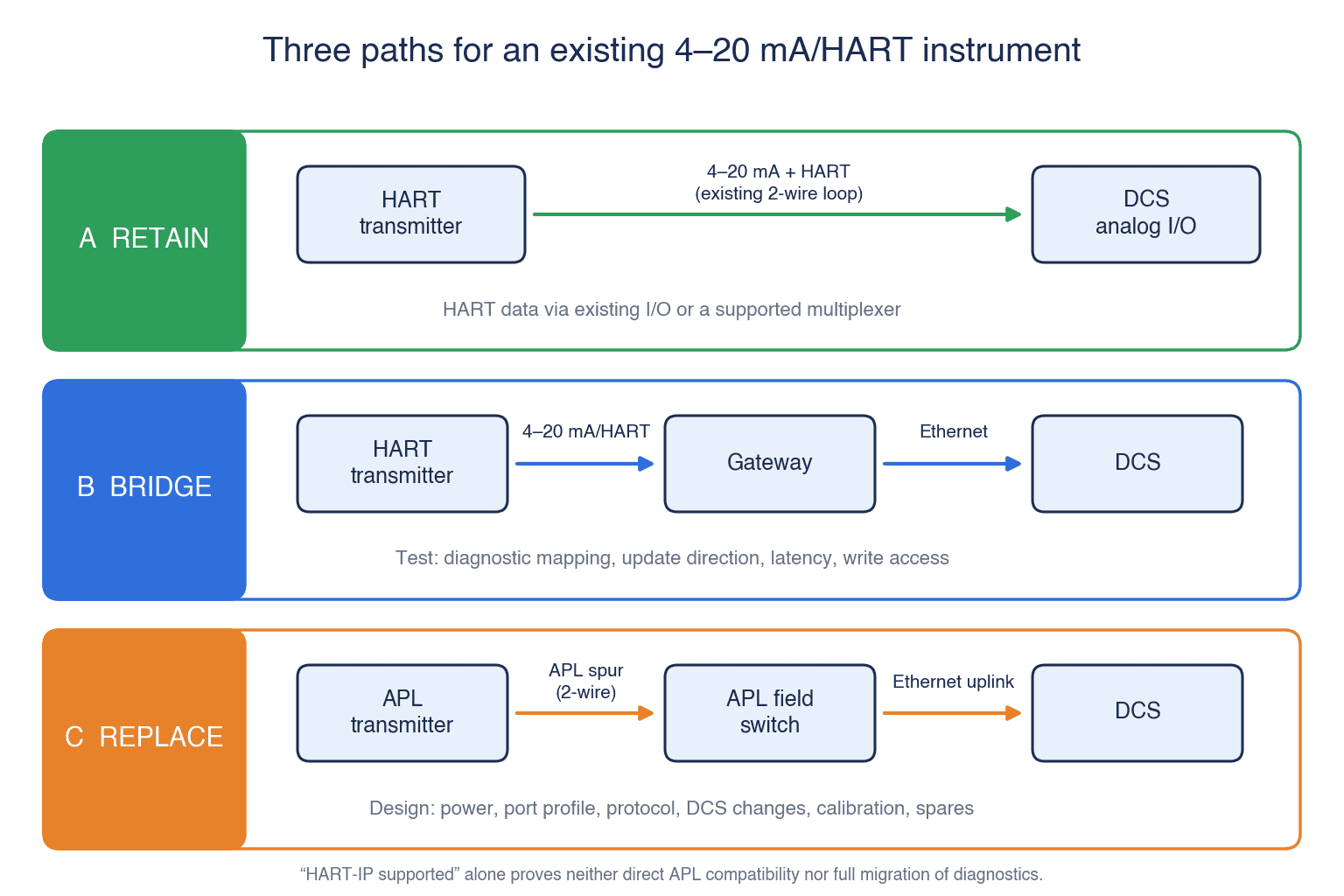
An existing 4–20 mA/HART transmitter cannot simply be connected to an APL spur and become a native Ethernet device. Compare three paths. A: retain the analog loop and improve access to HART data through existing I/O or a supported multiplexer. B: bridge the legacy instrument through a specified gateway, with explicit limits for diagnostic mapping, update direction, latency and write access. C: replace it with a native APL instrument and design its power, port profile, higher-level protocol, DCS changes, calibration and spares. The label “HART-IP supported” by itself proves neither direct APL compatibility nor complete migration of the existing diagnostics.
Compare retention, bridging and replacement on the same basis
| Option | Suitable when | Main risk to test | Decision evidence |
|---|---|---|---|
| Retain 4–20 mA/HART | Control is stable; additional diagnostics have limited value | Aging I/O, noisy loop, access to HART data | Current loop test and maintenance record |
| Bridge legacy instruments | A short shutdown and incremental data access matter | Mapping, dropped values and gateway ownership | Live test using the named instruments |
| Replace with APL devices | Instruments are due for renewal and rich data has a defined use | Power, protocol, DCS, certification and cutover | FAT and SAT records on the actual design |
Retention requires work: measure the present loop quality, HART access, calibration burden and remaining support life. It provides the baseline against which a new system must earn its cost. Bridging can reduce field changes but introduces a conversion point and another support contract. Replacement can simplify some data paths, yet may also require new DCS interfaces, software licences, tag definitions and staff skills. Assess safety-instrumented functions under their own change-control process; do not approve an SIS change inside a general-control pilot.
Avoid the assumption that a faster physical link automatically improves control. Update periods, tolerable delay, fail-safe behaviour and availability belong to the full control design. Ask who will diagnose a switch fault during a night shift and who can restore a spare device. An architecture the local team cannot maintain is not an improvement.
Survey usable cable routes, not just cable counts
Build a loop inventory with tag, model, measurement range, DCS card, HART functions, cable type and cross-section, shield, junction box, route length, bonding, hazardous-area classification and shutdown window. Mark every mismatch between drawing and actual installation with a photograph and measurement. A line on an old drawing is not evidence that it can carry APL.
The Alliance FAQ says existing shielded cable, especially suitable Type A cable, may be reusable, but recommends testing it. Older cable may have no specified performance at the higher frequencies involved; usable length can be shorter than an ideal design figure. Inspect connections and screen continuity, measure the route and apply the engineering guideline and vendor criteria. Include a new-cable contingency with price and schedule in the RFP.
APL literature cites design limits of up to 1,000 m for a trunk and up to 200 m for a spur. Those are architecture limits under defined conditions, not guarantees for a particular existing cable. The allowable design depends on cable, power, number of devices, port profile, ambient conditions and installation. Complete the power and cable calculations for the chosen models before making a distance contractual. A design using conventional industrial Ethernet closer to field switches may be simpler than a long powered trunk.
Write the field-switch specification port by port
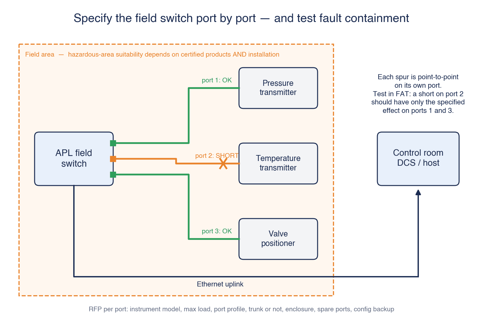
“Eight-port APL switch” is too weak an RFP description. State the instrument model and maximum load at each spur, required port profile, whether a trunk is used, upstream interface, installation location, temperature, enclosure rating, terminals and spare capacity. For multi-vendor combinations, ask for the exact physical-layer and application-protocol conformance evidence. Include switch management access, configuration backup, firmware procedure and logs in the deliverables.
Specify fault containment. What happens to other ports when one spur is shorted? How do ports restart after power returns? Upstream redundancy does not make the point-to-point connection between field switch and instrument redundant. If the measurement itself must survive one instrument failure, design separate instrument or application redundancy. A switch with useful diagnostics still needs a person and a procedure to use them.
Hazardous-area suitability is specific to products and installation
APL supports hazardous-area designs, including the 2-WISE intrinsically safe approach, but APL branding does not certify every switch or instrument for every zone. The Alliance FAQ explicitly ties permissible installation to the manufacturer’s product design and requires field-device certification for the installation location. Obtain certificates and conditions for each port and device, then match them with the site’s zone, gas or dust conditions, cable, junction box and installation method. Have the qualified hazardous-area designer confirm the locally applicable rules and plant requirements in Thailand.
Replacing a barrier or junction box affects the shutdown and permit scope. Even a non-hazardous food process may impose washdown, humidity, chemical and temperature requirements. Treat environmental protection and explosion protection as separate questions. Also specify the bonding and shielding design. The Alliance explains that APL conductors need appropriate isolation from ground plus functional bonding and shielding. Do not copy a legacy 4–20 mA grounding sketch without engineering review. Some measurements can be simulated at FAT; installed bonding and cable condition belong to SAT.
Map meaning and quality, not just the process value
A visible process value is insufficient acceptance evidence. Define tag, unit, range, timestamp, quality status, device diagnostics, alarm priority and change history. Decide which system owns each field when data pass through the DCS, historian, maintenance application and MES. Give the conversion table a version and an owner. For bridged HART data, test source code against displayed destination code; an unmapped warning should not silently become “healthy.”
For control, specify what happens to a stale value: hold-last-value, bad-quality flag, alarm, transition to a safe state or another approved action. The control engineer must set the permitted period for each loop; a single blog-wide millisecond target would be misleading. Test clock alignment, event order, planned outages and recovery. When process readings are linked to production lots, preserve enough timestamps and quality information to reconstruct which reading informed which event.
Our OPC UA migration and certification guide addresses the upstream data boundary. Use it alongside a system-specific test from field device to consuming application. Our OT security RFP guide helps specify allowed flows, maintenance access, logs and recovery when the new network reaches further into the plant.
A realistic 90-day proof of concept
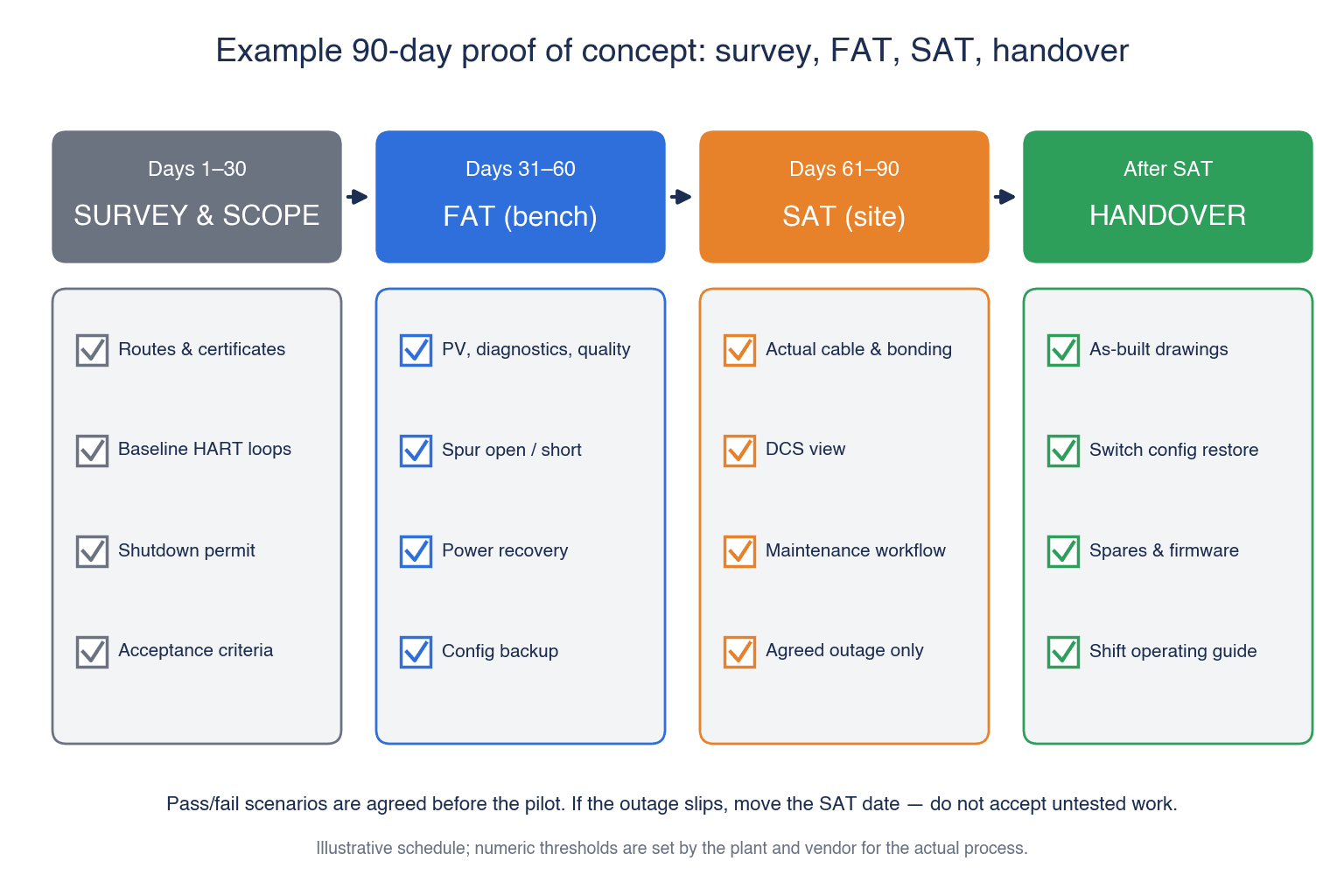
Ninety days is an example decision period, not a promise to retrofit an entire plant. Select one process area or junction-box cluster, with a small representative set of different device models. Avoid SIS points in the first general-control pilot. In a chemical plant, choose a non-SIS measurement with an approved outage; in a food plant, consider a tank or filling process whose cleaning conditions are known. Too many tags mix wiring, DCS and maintenance problems; only one easy tag hides interoperability and fault-containment issues.
Days 1–30: survey routes and certifications, record existing 4–20 mA/HART performance, establish the scope, shutdown permit and acceptance criteria. Days 31–60: perform FAT with the named or equivalent instruments, switch and host; test data, faults, power recovery, quality flags and backups. Days 61–90: install in the agreed outage and perform SAT on the actual cable, bonding, DCS view and maintenance workflow. If the outage is delayed, move the SAT milestone. Do not accept untested work merely to preserve a calendar date.
Agree observable pass/fail scenarios before the pilot: named process value, diagnosis and quality appear in both DCS and maintenance screens with traceable timestamps; a spur disconnection and short produce the specified effect without an unexplained impact on other instruments; a replacement switch restores the saved configuration. The plant and vendor set numeric thresholds for the actual process and contract. These examples are not universal performance guarantees.
What the RFP and quote must contain
Chapter one should list included and excluded tags, drawings, hazardous areas, shutdown constraints, retained analog loops and APL replacements. Chapter two specifies the data: values, diagnostics, settings, consumers, quality, time, write permissions and loss-of-communications response. Chapter three specifies switch and power design, each spur, trunk if used, cable testing and certification. Chapter four specifies operation: asset register, backups, spares, local support hours and languages, firmware and training.
Ask for separate prices for instruments, switches, power, junction boxes, cabling, hazardous-area installation, DCS or gateway changes, licences, FAT, SAT, shutdown, training, spares and annual support. Request an optional line for cable replacement if reuse fails. State who maps tags, approves DCS changes, repairs SAT failures and issues as-built drawings. A low lump sum with interface work excluded is not comparable to a complete bid.
| Deliverable | Evidence | Acceptance owner |
|---|---|---|
| Site survey | Tags, routes, area classification and outage record | Plant instrumentation, production and EHS |
| Selection | Model-specific power, ports, protocol and certificates | Instrument and DCS engineers |
| FAT | Configuration, procedure, data and fault logs | Plant and vendor |
| SAT | Cable readings, installation, control view and recovery demonstration | Plant maintenance and EHS |
| Handover | As-built drawing, backup, spares and training | Maintenance team |
Compare total cost under explicit site assumptions. For an *illustrative* 20-loop case, option A includes continued instrument maintenance, better HART access and fault response; option B adds gateways and their support; option C includes 20 new instruments, switches, power, wiring, DCS change, outage and support. Twenty loops is a calculation example, not a recommended size or market quote. Put initial cost, five-year operating cost, shutdown time, licences and spares on the same worksheet. Estimate benefits only from measured local records, such as annual manual checks multiplied by verified time saved and labour cost. Do not turn a promise of “more data” into an unsupported failure-reduction percentage.
FAT, SAT and ownership after acceptance
At FAT freeze model and firmware versions and connect the actual intended devices where possible. Test normal readings, diagnostics, unplugged and shorted spurs, switch power loss, upstream link loss, stale timestamps, replacement and configuration restore. Record expected DCS value, quality, alarm and recovery for each action. A certificate does not replace a system-specific tag and unit test.
At SAT measure the installed route, shielding and bonding; check enclosure, labels and hazardous-area evidence against the delivered models. Reconcile the same event across DCS, historian and maintenance screens with timestamps. If a fault injection would be unsafe on a running process, agree a risk-based substitute and document what remains untested. Keep failures, retests, exemptions and signatories in the acceptance record.
Build a test register before signing the contract: action, expected result, measurement, evidence location and approver. For example, vary a simulated process input, compare its value and unit across screens, disconnect one instrument and examine other ports, then restore the switch from backup. Use the same tag list and site assumptions for every bidder. Record exclusions, unit rates for changes, local replacement stock and Thai-language support. An attractive price cannot resolve an untested protocol interface; assign an owner and date to each open interoperability question.
After go-live, field instruments are part of an Ethernet network. Allocate address management, user permissions, logs, firmware, spare replacement and backup ownership between instrumentation, maintenance and OT. Recalculate power, length, zone compliance and licences whenever instruments are added. Segment upstream traffic and control vendor remote access through a plant-approved process. Train the Thai maintenance team to interpret both switch diagnostics and DCS quality status, and rehearse restoration rather than merely storing a backup file.
Sequence the cutover around production
Do not rank loops by equipment age alone. Compare the next planned outage, spare availability, access to cable routes and whether DCS logic changes can be tested in the same window. Ten instruments may share a junction box while only three need replacement; the other seven do not acquire a business case merely because they share a box. Conversely, if a junction box is being fully renewed, compare the added cost and shutdown risk of deferring adjacent wiring. In food processing, include cleaning and quality-release time. In chemical processing, include purging, permits and safe restart. An estimate based only on the minutes needed to replace a transmitter omits the work that dominates the outage.
Agree a rollback point for each phase before fieldwork. Save the existing I/O configuration, terminal assignments and spares. Define who authorizes a return to the 4–20 mA arrangement, how the old loop will be reconnected, and which loop tests prove it is safe to resume. Procurement should know what happens if the cutover is postponed or a system cannot be accepted before the production window ends. The pilot proves only the tested combination of instrument model, firmware, cable, distance, switch and host. Record that combination as the validated envelope and reassess every difference at the next site.
Test lot boundaries when process data feed quality records
In a food plant, collecting temperature or pressure is not itself traceability. Define which product lot passed through which asset, how measurement time relates to process start and finish, and how missing readings are displayed. At a filling line, a lot changeover can coincide with a reading; values collected during cleaning should not silently enter a product batch record. The pilot should test changeovers, stops, restarts and corrected clocks, not merely a clean day of operation. Ask the quality team to reconstruct an actual lot history from the pilot data.
In a chemical process, do not confuse an instrument diagnostic warning with a confirmed product-quality deviation. Communication may be poor while an independent measurement still supports process assessment; a plausible-looking value may also coexist with a device self-diagnostic fault. Keep measured value, communication quality, device diagnosis and quality decision as distinct fields and displays. Assign ownership for the value to instrumentation, for lot disposition to quality, and for record retention to the appropriate system owner. Include those distinctions in the handover document.
Give management a decision sheet and the shift team an operating guide
The first page for management should show the target process, present measurable loss, included tags, required outage, the range of cost for the three options, the pilot pass criteria and the date of the next investment decision. The second page should show the cable-reuse condition, open hazardous-area questions, protocol tests and circumstances that raise cost. Do not leave unknowns blank: write who will measure what to resolve them. Report improvements using the same method before and after the pilot: maintenance time, availability of needed diagnostics, recovery duration and the share of lot records that can be reconciled. If the result does not support expansion, revise the design or keep existing loops.
The operating guide should be usable by the Thai shift team. List each port and connected tag, normal switch and DCS quality indications, steps to check safety before troubleshooting, escalation contacts, spare location, and configuration restore procedure. Decide which supplier receives the first call so a switch maker, instrument maker and DCS vendor do not pass a fault among themselves. After handover, log when and where a fault occurred, power and uplink status, DCS quality indication and impact on adjacent devices. Have actual operators follow the guide during a switch replacement and restore exercise. An attendance sheet alone is weak evidence of readiness.
Frequently asked questions
Can an existing 4–20 mA/HART transmitter connect directly to an APL field switch? Normally no. Compare retained I/O, a proven gateway or replacement with a native APL device. Test any exceptional converter claim with the exact instrument and host.
Does cable reuse make the installation free? No. Survey and testing are needed, and power, switch, junction-box, grounding and possibly hazardous-area work remain.
Should every loop migrate at once? No. Compare condition, renewal date, diagnostic value and outage risk loop by loop. Expand from a representative accepted pilot.
Does APL automatically provide explosion protection or cybersecurity? No. Product certificates, appropriate installation and a system security design are separate evidence.
Conclusion: accept one representative instrument group before scaling
An Ethernet-APL purchase decision needs a comparison against keeping 4–20 mA/HART, an assessed cable route, a chosen application protocol, location-specific approvals, and an outage plan. A 90-day pilot should prove values, diagnostics, quality and fault behaviour through FAT and SAT. Scale only after the evidence and local operating responsibilities are clear.
Planning an APL pilot in a Thai plant? TOMAS TECH can help map your existing HART loops, define the RFP boundary and prepare the FAT/SAT evidence plan. Contact our team with your target process and instrument list.


