


“When we lined up the MES records, the PLC alarms and the inspection machine records during a defect investigation, the times were off by a few seconds each, and we could not tell what happened first.” We often hear this from Japanese-owned factories in Thailand. What you should aim for in a factory time synchronization implementation is not an accuracy figure as such. It is being able to explain which record was stamped by which clock, and with how much error. To get there, you decide five things: (1) the required accuracy for each use case, (2) the time source and distribution method, (3) how timestamps are applied, (4) security and monitoring, and (5) acceptance testing.
Figures in this article that carry no cited source (line speeds, error allocations, outage durations and the like) are original assumptions created for this article, based on the model factory described later. They are neither industry averages nor survey results. The holdover performance of oscillators is the manufacturer’s published value and has not been verified by a third party. None of the products or vendors mentioned are TOMAS TECH’s own; they all belong to other companies.
Why Factory Time Synchronization Is Being Questioned Now
June 2026: IEC/IEEE 60802, the TSN profile for industrial automation, is published
This year marked a major milestone for factory networks and time. According to the IEEE 802.1 project page, the project for “IEC/IEEE 60802”, the TSN (Time-Sensitive Networking) profile for industrial automation, was approved on 21 September 2022, and the first edition was published on 29 June 2026. A standards retail site also lists it as ed.1.0 (29 June 2026, 220 pages).
The standard selects and defines, for industrial automation, the features, options, configurations, defaults, protocols and procedures of bridges (switches), end stations (devices) and LANs. For time synchronization, it assumes IEEE 802.1AS (gPTP), and topics such as modeling of synchronization error, drift tracking and oscillator frequency stability have been studied. IEEE 802.1AS, its foundation, has seen its 2020 edition superseded by the 2025 edition, and a revision project for the 2025 edition was approved on 15 May 2026 and is in progress.
October 2026: the international conference that will decide the future of the leap second
The other milestone concerns the leap second. In 2022, the 27th General Conference on Weights and Measures (CGPM) resolved to increase the maximum value of the difference between UT1 and UTC “in or before 2035”, and asked the International Committee for Weights and Measures (CIPM) to prepare a concrete proposal so that it could be approved at the 28th meeting in 2026. According to the convocation from the International Bureau of Weights and Measures (BIPM), the 28th CGPM will be held in Versailles, France, from 13 to 15 October 2026, and the agenda includes “technical measures needed to ensure the continuity of UTC” and “the future definition of the second”. At the time of writing (7 October 2026), the meeting has not yet taken place, and what will change and from when has not been decided. Note that Bulletin C 72 (6 July 2026) of the International Earth Rotation and Reference Systems Service (IERS) states that no leap second will be introduced at the end of December 2026.
GNSS radio interference continues in Asia-Pacific
There is also regional news about GNSS (satellite positioning systems such as GPS), which is widely used as a time source. According to an information paper submitted by Indonesia to the 61st Conference of Directors General of Civil Aviation, Asia and Pacific Regions (DGCA-61), held in Kuala Lumpur in September 2026, GNSS interference occurred in the Jakarta flight information region on 8 April 2026, affecting 44 commercial flights arriving at and departing from Soekarno-Hatta International Airport, and air traffic control responded with measures such as conventional navigation procedures. In addition, a secretariat paper for a meeting of the International Civil Aviation Organization (ICAO) Asia and Pacific region (APRAST/25), held in Bangkok in June 2026, states that GNSS radio frequency interference, including jamming and spoofing, continues to be an operational and safety risk in the region.
This is an aviation incident, not a report that GNSS receivers at factories were affected. Nor have we found any cases of damage at factories in Thailand. Still, the fact that disruption of GNSS signals is treated as a real risk in the region is, in our view, something that cannot be ignored when designing a factory’s time source.
What this means for factories in Thailand
The publication of a TSN standard does not mean you need to replace existing lines right away. However, the control devices and switches you procure over the next few years are likely to come with time synchronization features as standard. Without a “factory time policy” at that point, each device will arrive with its own time source and settings. The leap second and GNSS interference also show that time is not something you “install and forget”, but something to specify, monitor and test.
What Is Factory Time Synchronization: Why Timestamps Determine Traceability
The role of time synchronization
A factory contains many devices that each have an internal clock: PLCs, HMIs, SCADA servers, historians, MES, inspection machines, vision cameras, network equipment, IT servers and more. Left alone, each clock gradually drifts. When devices whose time was set by hand, devices nobody has checked since, and devices that started with a default time after a power outage are mixed together, the same event is recorded with different times on different devices. Time synchronization is the mechanism that keeps all these clocks aligned to one reference.
Timestamps become the “key” linking records together
In a traceability investigation, you link product serial numbers, lots, equipment and time to trace “when, on which equipment and under what conditions this product was made”. In processes where the product number cannot be written directly into the equipment records, time is often the only key linking records together. For example, a molding machine’s process values are recorded in the historian, inspection results in the MES, and alarms in the SCADA, each by a different clock. If the clocks drift, records get linked incorrectly. The overall design for linking equipment history to products is covered in “Production Equipment Traceability: Machine-to-Part RFP and FAT/SAT“.
The same applies to alarm sequences. When investigating the cause of a stoppage, whether “the pressure dropped first or the pump stopped first” can only be determined by the order of the timestamps. If the difference between two devices’ clocks is larger than the interval between events, the order can appear reversed.
“Being able to explain” matters more than “accuracy”
Discussions of time synchronization tend to become a race of numbers such as “how many microseconds” or “how many nanoseconds”. However, what is asked during an audit or a defect investigation is: “Which clock applied the time on this record, was that clock synchronized at the time, and how large can the error be estimated to be?” In this article, we consider the value of time synchronization to be the ability to explain the following three points.
- Which clock: which device applied the time on that record (near the sensor, or when it reached the server)
- In what state: whether that clock was synchronized to the reference at the time, or had lost the reference and was free-running
- With how much error: how large the offset from the reference can be estimated to be, and whether this can be shown from monitoring records
If these three points can be explained, some factories will find millisecond accuracy entirely sufficient. Conversely, even with nanosecond-class equipment, if you cannot tell which clock a record came from, it is of no use in an investigation.
Decide the Required Accuracy from the Use Case
Time synchronization design fails if it starts from “which method to install”. The first thing to decide is, for each use case, “which records you want to compare with which, and at what granularity”. There are two kinds of accuracy: the difference between devices within the factory (relative accuracy) and the difference from Coordinated Universal Time (UTC) (absolute accuracy). Relative accuracy matters for knowing the order of events within the factory; absolute accuracy matters for comparing records with other factories, headquarters, business partners or cloud systems.
| Use case | Records to compare | How to decide the required accuracy (this article’s view) | Candidate methods |
|---|---|---|---|
| Daily reports, shifts, utilization | Production results and time slots | Sufficiently smaller than the aggregation unit (minutes or hours) | NTP |
| Linking products or lots to equipment records | MES product records and historian process values | Decide from the interval between products (see the model later) | NTP, or PTP depending on line speed |
| Analyzing the order of alarms and events | Alarms from multiple PLCs or SCADA | Sufficiently smaller than the interval between the events you want to investigate | NTP or PTP |
| Correlating quality with other factories, headquarters or the cloud | Records spanning sites | Decide by the difference from UTC (absolute accuracy) | NTP (with emphasis on traceability of the time source) |
| Audit trails in regulated industries | Date and time of creating or changing electronic records | Regulations do not specify an accuracy figure, so set it in internal procedures and keep the rationale | NTP |
| Control and measurement that assume synchronization | Timing of operations or measurements between devices | Follow the requirements of the device or control manufacturer | PTP (IEEE 802.1AS or industrial profiles) |
| Power equipment such as substations | Protection and metering devices | Follow power equipment standards and device requirements | PTP (power profile) |
The “candidate methods” column is a general trend organized by this article and will vary with device and network conditions. What matters is to derive the required figures not by working backwards from a method, but from “what you want to compare with what”. Even within the same factory, the required accuracy can differ by several orders of magnitude depending on the use case. There is no need to bring everything up to the highest accuracy.
The Difference Between PTP and NTP
The methods commonly used in factories to distribute time over a network are NTP (Network Time Protocol) and PTP (Precision Time Protocol, IEEE 1588).
NTP: widely usable on existing networks
The current version of NTP (NTPv4) is defined in RFC 5905 (June 2010). On accuracy, RFC 5905 states that a typical primary server is within a few tens of microseconds, typical secondary servers and clients on fast LANs are within a few hundred microseconds (with poll intervals up to 1,024 seconds), and with poll intervals extended up to 36 hours, within a few tens of milliseconds. These describe typical values at the time the RFC was written and are not guaranteed values. Actual accuracy varies with network load, path, distance to the server and device implementation.
NTPv5, the next version of NTP, is still at the IETF draft stage as of October 2026 (draft-ietf-ntp-ntpv5-09, dated 1 July 2026) and has not become an RFC. The draft makes the client-server model the only mode of operation, but the specification may still change.
PTP: high accuracy with the cooperation of network equipment
The current PTP standard is IEEE 1588-2019, approved on 7 November 2019 and published on 16 June 2020. The IEEE abstract states that it achieves synchronization “in the sub-microsecond range” with minimal resources, and that “sub-nanosecond time transfer accuracy” may be possible in a properly designed network. The important point here is the condition “in a properly designed network”. Using PTP does not automatically deliver high accuracy; results vary greatly depending on whether devices apply timestamps in hardware and whether PTP-aware switches (BC and TC, described later) are present.
| Aspect | NTP | PTP (IEEE 1588) |
|---|---|---|
| Standard | RFC 5905 (NTPv4). NTPv5 is at the draft stage | IEEE 1588-2019 (with several amendments) |
| Accuracy as described | The RFC describes typical clients on fast LANs as within a few hundred microseconds (typical value) | The standard’s abstract describes the sub-microsecond range, and possible sub-nanosecond accuracy in a properly designed network |
| Network requirements | Works on ordinary IP networks | High accuracy often requires PTP-aware switches and hardware timestamping |
| Main users | IT servers, SCADA, MES, historians, many PLCs and HMIs | Control and measurement that assume synchronization, TSN, power equipment, records on high-speed lines |
| Authentication | NTS (RFC 8915) can verify the authenticity of time packets | Not covered in this article; check for each product |
| Implementation burden | Small. Supported by most existing devices | Large. Requires checking support in switches and devices |
Note: the “main users” and “implementation burden” rows are this article’s own summary.
The accuracy row simply sets side by side what each standards document states; neither is a measured value in a factory. Rather than choosing by the simplistic contrast “NTP is milliseconds, PTP is nanoseconds”, what matters is to check what your own network can deliver against the required accuracy decided in the previous section.
A configuration that uses both is realistic
In many factories, a configuration combining both is likely to be realistic. From the same time source (the grandmaster clock, described later), PTP is distributed to control networks that need high accuracy, and NTP to IT servers, SCADA and MES. This way, even though the methods differ, every time in the factory can be traced back to the same reference.
Time Source, GNSS and Holdover

Time source options
There are two main ways to obtain the factory’s time reference. One is to install a GNSS antenna on the roof or similar location and obtain time from satellite signals. The other is to synchronize over the network to time servers provided by organizations such as Thailand’s National Institute of Metrology (NIMT). NIMT is covered in detail in the Thailand and ASEAN section later.
GNSS time is highly accurate; according to the U.S. National Institute of Standards and Technology (NIST) document “NIST IR 8323r1” (January 2023), GPS time, once the whole-second difference due to leap seconds is corrected, is kept within 1 microsecond of the U.S. Naval Observatory’s UTC (UTC(USNO)). The caveat is that GPS time is a time scale that is not adjusted for leap seconds. According to an explanatory article by an NIMT engineer, GPS time has its origin at 00:00 UTC on 6 January 1980, and International Atomic Time (TAI) is 19 seconds ahead of GPS time. According to IERS Bulletin C 72, UTC is 37 seconds behind TAI, so by calculation, GPS time is 18 seconds (37 − 19) ahead of UTC. Whether the receiver correctly corrects for this difference is one of the points to check in acceptance testing.
Grandmaster clocks and holdover
The device that serves as the origin of time within the factory is called the grandmaster clock (GM, grandmaster). A dedicated device with a built-in GNSS receiver and oscillator that distributes time via PTP or NTP is common.
What makes the biggest difference when selecting a GM is how well it can keep correct time when GNSS is lost, in other words its holdover performance. When GNSS cannot be received due to antenna cable damage, lightning, radio interference and so on, the GM keeps time using only its internal oscillator. The rate at which it drifts varies greatly with the type of oscillator.
According to Meinberg’s oscillator options table, PPS (pulse per second) accuracy while synchronized to GNSS is better than ±100 nanoseconds for TCXO and OCXO-LQ, and better than ±50 nanoseconds for OCXO-SQ, HQ, DHQ and rubidium. The phase offset 24 hours after losing GNSS is as follows.
| Oscillator (Meinberg’s classification) | Phase offset after 24 hours of holdover (company’s published value) |
|---|---|
| TCXO | ±4.3 milliseconds |
| OCXO-LQ | ±865 microseconds |
| OCXO-SQ | ±65 microseconds |
| OCXO-HQ | ±10 microseconds |
| OCXO-DHQ | ±4.5 microseconds |
| Rubidium | ±800 nanoseconds |
In the same table, after 7 days the range widens from ±128 milliseconds for TCXO to ±34 microseconds for rubidium, and after 30 days from ±1.1 seconds for TCXO to ±370 microseconds for rubidium. The difference between TCXO and rubidium after 24 hours is 4.3 milliseconds ÷ 800 nanoseconds, about 5,375 times, in other words more than 5,000 times (this article’s calculation).
However, these are the manufacturer’s published values and, according to the table’s footnotes, assume an oscillator that has been running for at least 30 days and has been continuously disciplined by GNSS for the preceding 24 hours, as well as a constant ambient temperature. In locations where the temperature changes, such as inside a factory panel, performance may be worse than this. In our view, the safe approach is to use these figures as a guide when choosing an oscillator, and to include verification under your own installation conditions in acceptance testing.
How to choose a grandmaster clock
As this article’s view, here are the points to check when choosing a GM.
- Holdover requirement: estimate how many days it could take from losing GNSS to recovery (night and holiday maintenance arrangements, parts procurement), and decide the oscillator class from the offset you can tolerate during that period
- Output methods: whether it supports the PTP profiles (described later), NTP and, if needed, outputs such as PPS
- Redundancy: whether to have two GMs, or two time source paths, GNSS and network (NIMT and others)
- Monitoring features: whether it can export synchronization status, satellite reception status, the time it entered holdover and the estimated error via SNMP or logs
- Detection of GNSS anomalies: whether it can detect signs of radio interference or spoofing, and compare multiple time sources
- Antenna installation: the cable route from the roof to the server room, lightning protection and ease of maintenance
PTP Network Architecture: GM, BC, TC and Profiles

Types of PTP devices
A PTP network is built from a combination of devices with different roles. According to the explanation in H3C’s configuration guide, the roles are as follows.
- Grandmaster (GM): the origin of time within the PTP domain. It is selected automatically among the clock nodes
- Ordinary clock (OC): a device with only one PTP port (this article’s example: end devices such as PLCs and I/O)
- Boundary clock (BC): has multiple ports, synchronizes to the upstream on one port and distributes time downstream on the other ports
- Transparent clock (TC): does not keep time itself, but forwards PTP messages while correcting for the delay incurred in transit. There is the E2E type, which forwards all PTP packets and supports calculating the delay of the whole link, and the P2P type, which forwards only some messages and terminates the rest
The same guide lists IEEE 1588v2, IEEE 802.1AS, SMPTE ST 2059-2 and AES67-2015 as supported standards. They are introduced here as an explanation of general PTP concepts, not as a recommendation of any particular product.
Points to consider in the architecture
Because the GM is selected automatically, it is safer, in our view, to include in the design both priority settings and monitoring of which device is acting as GM, so that an unintended device does not become the GM. Also, if an ordinary switch that does not support PTP is placed in the path, no delay correction takes place on that segment. For segments that need high accuracy, check in the equipment list whether the switches along the path operate as a BC or TC.
Profiles: rules for “how PTP is used” per application
PTP has “profiles” that narrow down how it is used for each application. The three most likely to be relevant in factories are as follows.
- General-purpose IEEE 1588: usage not narrowed to a specific application
- IEEE 802.1AS (gPTP) and IEC/IEEE 60802: for TSN. 802.1AS covers time transfer, selection of the best time source, and detection of phase and frequency discontinuities. After the 2020 edition, amendments addressing hot standby and reduction of clock drift error were issued, and the 2025 edition is now current. IEC/IEEE 60802 is a profile for industrial automation that builds on it
- IEC/IEEE 61850-9-3: a PTP profile for power utility automation (published 31 May 2016). Based on IEC 61588:2009 (IEEE 1588-2008), it makes it possible to comply with the highest synchronization classes of IEC 61850-5 and IEC 61869-9. It may be relevant for a factory’s substation and on-site power equipment
Even with the same PTP, devices with different profiles may not work together on the same network as they are. In the RFP, the reliable approach is to ask suppliers to state not “PTP support” but “which profiles are supported”.
How to Apply Timestamps: OPC UA, PLC, Historian and MES
The meaning changes with “where” the time is applied
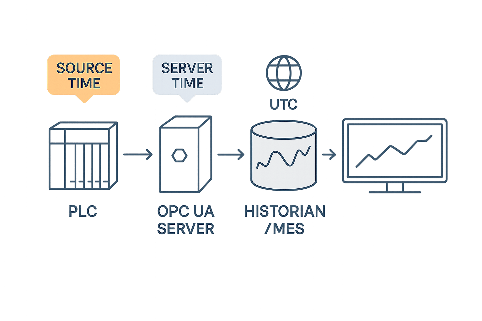
Even with synchronized clocks, the meaning of records becomes uncertain if it has not been decided where timestamps are applied. A time applied near the sensor or PLC at the moment a value changed and the time the server received the value differ by the communication delay. If data that was held up by a temporary communication stoppage and arrives later all at once is given its arrival time, cause and effect can appear in the wrong order.
OPC UA SourceTimestamp and ServerTimestamp
OPC UA builds this distinction into its specification. According to the definition of DataValue in the OPC UA specification (Part 4, v1.05), there are two timestamps.
- SourceTimestamp: the time the data source applied to the value. Once applied it does not change, and it should indicate the time of the last change of the value or status code. It should be generated as close as possible to the source of the value, but must always be applied by the same physical clock. In redundant configurations, the clocks of the sources should be synchronized. Also, when an OPC UA server receives data from another OPC UA server, it passes the SourceTimestamp on unchanged
- ServerTimestamp: the time the server received the value (or knew it to be accurate). Each server applies its own value
Both have a field that allows a resolution of 10 picoseconds to be specified. However, this is the definition in the specification. Which time a real PLC or gateway applies, and with which clock, differs by product. The words “OPC UA compatible” alone do not tell you whether the SourceTimestamp is the time the value changed inside the PLC or the time the gateway read it. For approaches to OPC UA version migration and certification, see also “OPC UA 1.05 Migration: RFP, FAT and SAT for Thailand Factories“.
Decisions for PLCs, historians and MES
As this article’s view, we recommend deciding the following about timestamps as factory policy and documenting them.
- Where the time is applied: for each use case, whether SourceTimestamp or ServerTimestamp is authoritative. If a PLC cannot apply the time of a value change, state explicitly that the time is when the gateway read it
- Which clock applies the time: to which time source, and by which method, the device applying the time is synchronized
- Time scale for storage: store in Coordinated Universal Time (UTC) and convert to Thai local time (UTC+7) when shown on screens or in reports
- Recording time anomalies: whether records applied while synchronization was lost can be marked as such
The reason for storing in UTC is to keep time comparisons simple. Thai time has no daylight saving time, so even if you store local time, the time never jumps during the year. Even so, when comparing records with headquarters in Japan, sites in other countries or cloud systems, holding them in UTC is likely to reduce conversion errors.
How to keep timestamps and quality in a historian is covered in “Industrial Historian Selection: RFP and FAT/SAT in Thailand“, and design for sending equipment data via MQTT in “MQTT Sparkplug B implementation in Thailand: RFP, FAT/SAT and a 90-day pilot“. Whatever path the data takes, it is important not to lose “which clock applied this time” along the way.
Handling leap seconds
A leap second is an adjustment that inserts or deletes one second in UTC. NTP packets have a 2-bit “leap indicator” field, which signals an upcoming insertion or deletion of a leap second in the last minute of the month, as well as an “unsynchronized” state. As mentioned earlier, no leap second will be inserted at the end of December 2026, and the future handling of leap seconds is still at the stage of discussion at the October 2026 meeting. For a factory, the realistic approach, in our view, is to check in the specifications how the GM, NTP servers, PLCs and historian will each behave when a leap second occurs (how they handle the indicator and how they adjust time).
Estimating Line Speed and Clock Offset with a Factory Model (Assumed Model)
All figures from here on are assumptions set by this article. They are not product performance or industry averages. Use them as a calculation template and replace them with your own line speeds and use cases.
Assumptions (Model Factory T)
| Item | Assumption |
|---|---|
| Factory | A Japanese-owned parts factory in central Thailand with three lines |
| Line A | 60 parts per minute (interval of 1,000 milliseconds per part) |
| Line B | 600 parts per minute (interval of 100 milliseconds) |
| Line C | 6,000 parts per minute (interval of 10 milliseconds) |
| Decision rule | Records can be linked to the correct part if the clock difference between two devices is kept to one tenth of the part interval or less |
| Error allocation | Considering the case where two devices drift from the reference in opposite directions, the allowance per device is half the allowance between devices |
Step 1: derive the required accuracy
One tenth of the part interval is the clock difference that can be tolerated between devices. Dividing that by 2 gives how far a single device may deviate from the reference (the factory GM).
| Line | Part interval | Allowance between devices (one tenth of the interval) | Allowance per device (half of that) |
|---|---|---|---|
| A (60 parts per minute) | 1,000 milliseconds | 100 milliseconds | 50 milliseconds |
| B (600 parts per minute) | 100 milliseconds | 10 milliseconds | 5 milliseconds |
| C (6,000 parts per minute) | 10 milliseconds | 1 millisecond | 0.5 milliseconds (500 microseconds) |
Let us compare these with sourced figures. A 2018 article by an NIMT engineer stated that the accuracy of NIMT’s free time service over the internet was “better than 30 milliseconds, depending on internet traffic”. This was a guide at the time and not a guaranteed value, but if we apply this 30 milliseconds, it fits within Line A’s 50 milliseconds per device but not within Line B’s 5 milliseconds. Also, the “within a few hundred microseconds” that RFC 5905 describes for typical NTP clients on fast LANs leaves almost no margin against, or may exceed, Line C’s 500 microseconds.
What this model suggests is that, for Line A, NTP over the internet may be sufficient depending on conditions; for Line B, a configuration with an NTP server inside the factory distributing over the LAN is a candidate; and for Line C, PTP (hardware timestamping and PTP-aware switches) is worth considering. In every case, verification by measurement is a prerequisite.
Step 2: how many parts get mismatched when clocks are not aligned
Now consider the opposite case, where clocks are not aligned. Assume the clock of a PLC whose time was set by hand is 2 seconds off from the MES server.
| Line | Part interval | Linking mismatch caused by a 2-second offset |
|---|---|---|
| A | 1,000 milliseconds | 2,000 ÷ 1,000 = 2 parts |
| B | 100 milliseconds | 2,000 ÷ 100 = 20 parts |
| C | 10 milliseconds | 2,000 ÷ 10 = 200 parts |
Two seconds feels like a small offset to a person, but on Line C records are shifted onto different parts by 200 parts. When investigating the cause of a defect, you end up not looking at the process values of the right part, and the number of parts quarantined by taking a wide suspect range also increases.
Step 3: how long can you hold out when GNSS is lost
Finally, holdover. We compare Meinberg’s published values mentioned earlier (under ideal conditions such as constant temperature) with the per-device allowances from Step 1. What is compared here is the difference between the GM and UTC. If every device in the factory follows the same GM, the impact is small; this comparison is a guide for when records are compared with devices following a different time source or with UTC-based records (see the next subsection for details).
| Oscillator | Offset after 24 hours (company’s published value) | Line A (50 milliseconds) | Line B (5 milliseconds) | Line C (500 microseconds) |
|---|---|---|---|---|
| TCXO | ±4.3 milliseconds | Within (8.6% of allowance) | Within, but with little margin (86% of allowance) | Exceeds (8.6 times the allowance) |
| OCXO-LQ | ±865 microseconds | Within | Within (about 17% of allowance) | Exceeds (about 1.7 times the allowance) |
| OCXO-SQ | ±65 microseconds | Within | Within | Within (13% of allowance) |
| OCXO-HQ | ±10 microseconds | Within | Within | Within (2% of allowance) |
| OCXO-DHQ | ±4.5 microseconds | Within | Within | Within (0.9% of allowance) |
| Rubidium | ±800 nanoseconds | Within | Within | Within (0.16% of allowance) |
Let us also look at the case where the GNSS outage is prolonged. Assume the antenna cable is damaged during a long holiday and recovery takes 7 days. In the company’s table, TCXO after 7 days is ±128 milliseconds, about 2.6 times Line A’s 50 milliseconds (128 ÷ 50 = 2.56), exceeding even the allowance of the slowest line. Rubidium, on the other hand, is ±34 microseconds after 7 days and ±370 microseconds even after 30 days, staying within 74% of Line C’s 500 microseconds.
How to read this estimate: is it the “whole factory” or “only part” that drifts?
There is an important caveat here. The holdover offset is the difference between the GM and UTC. If every device in the factory is synchronized to the same GM, they drift together with the GM, so the difference between devices within the factory (relative accuracy) is unlikely to change much during holdover. The problems arise in cases such as the following.
- Some devices in the factory (for example, IT servers or cloud systems) are synchronized to a different time source (such as NTP over the internet)
- Records need to be compared with those of other factories or headquarters on a UTC basis
- When GNSS recovers, the GM’s time returns to the correct value all at once, and record times jump
In other words, what “exceeds” in the table indicates is that records may be linked incorrectly when compared with records that follow a different clock. Comparisons between records within the factory that follow the same GM are usually not significantly affected. Here too, knowing which record follows which clock pays off.
Points for checking the arithmetic
- 60 parts per minute = 1 per second, interval 1,000 milliseconds; 600 parts per minute = 10 per second, 100 milliseconds; 6,000 parts per minute = 100 per second, 10 milliseconds
- The allowance between devices is the interval ÷ 10, i.e. 100, 10 and 1 milliseconds; the per-device allowance is half that, i.e. 50, 5 and 0.5 milliseconds
- TCXO’s 4.3 milliseconds is 8.6% of 50 milliseconds, 86% of 5 milliseconds and 8.6 times 0.5 milliseconds
- Rubidium’s 800 nanoseconds after 24 hours is 0.8 microseconds, 0.16% of 500 microseconds
Security and Monitoring
NTS: verifying that NTP time is “genuine”
Time distributed over a network can be a target of spoofing or tampering. For NTP, there is NTS (Network Time Security), defined in RFC 8915 (September 2020). With NTS, keys are first established over TLS (1.3 or later) (NTS-KE, TCP port 4460), after which it is verified that subsequent time packets were sent by an identified party and were not altered in transit. It also provides replay protection and confirmation that requests and responses correspond.
Note that NTS is an “authentication” mechanism, not “encryption”. RFC 8915 considers basic time data to be non-confidential and sends it in plaintext. Also, when using NTS, you need to allow NTS-KE’s TCP port 4460 through the firewall in addition to NTP traffic (UDP port 123). Include both in the design of the firewall between the factory and IT.
Managing dependence on GNSS
NIST IR 8323r1 states that positioning, navigation and timing (PNT) signals and data can be subject to various disruptions and manipulation, natural and man-made, intentional and unintentional, and gives examples of threats such as radio interference, temperature changes, aging, vibration, power outages, jamming, spoofing and delay attacks. As countermeasures, it cites inventorying the HMI and control system software that depend on PNT, detecting anomalies by cross-checking PNT data from multiple sources, detecting GNSS jamming and spoofing, and building in standalone or holdover capability where needed. This is voluntary guidance for U.S. critical infrastructure and not a Thai regulation, but it is a way of thinking that applies directly to the design of a factory’s time source.
As this article’s view, it is realistic for factories to start with the following three points.
- List the devices that depend on time: which devices are synchronized to which time source, by which method
- Use two time source paths: cross-check the GNSS GM against a network time source such as NIMT, and raise an alarm if they disagree significantly
- Choose with holdover in mind: use an oscillator that can hold out within the allowance for the period until recovery, even after losing GNSS
Monitor offsets and keep records
Even if time synchronization is correct at installation, it can drift out later. Triggers can include cable replacement, changes to switch settings, equipment replacement and the start-up order after a power outage. As this article’s view, we recommend monitoring the following and keeping records.
- The GM’s synchronization status (whether it is receiving GNSS, whether it has entered holdover)
- The offset of major devices from the reference, and an alarm when it exceeds the allowance
- Which device is acting as GM, and when that changes
- The synchronization status of NTP clients
These monitoring records serve as evidence of the “ability to explain with how much error records were stamped” mentioned at the beginning, because they let you show during a defect investigation or audit that “at that time on that day, this device’s clock was correct within this range”. For how to build a safe path for passing monitoring data from the OT side to the IT side, “Industrial Data Diode Selection for Thai Factories: A Practical OT-to-IT Guide” is also a useful reference.
Regulated Industries: Audit Trails and Time
Factories that handle electronic records subject to U.S. Food and Drug Administration (FDA) regulation, for example for pharmaceuticals, medical devices or food bound for the United States, are subject to the requirements of 21 CFR Part 11. 21 CFR 11.10(e) requires the use of secure, computer-generated, time-stamped audit trails that independently record the “date and time” of operator entries and actions that create, modify or delete electronic records. Audit trails must be retained for the same period as the subject electronic records and be available for FDA review.
For GMP for medicinal products bound for the EU, EudraLex Volume 4 Annex 11 (current version, which came into operation on 30 June 2011) applies. Section 12.4 states that systems managing data and documents should be designed to record the identity of operators entering, changing, confirming or deleting data “including date and time”, and 14(c) requires electronic signatures to include “the time and date that they were applied”. Section 9 states that, based on a risk assessment, building into the system a record of GMP-relevant changes and deletions (a system-generated audit trail) should be considered.
A draft revision of Annex 11 was published by the European Commission and PIC/S on 7 July 2025, with the consultation open until 7 October 2025. According to commentary by ECA, a European professional organization, the draft grows from 5 pages to 19 pages and places much greater weight on security, identity and access management, and audit trails. However, this is a draft, and we have not been able to confirm the status of a final version or whether it contains specific requirements on time synchronization.
What we want to emphasize here is that neither 21 CFR 11.10(e) nor the current Annex 11 specifies time accuracy (within how many milliseconds) or a synchronization method (NTP or PTP). It is not the case that “regulations require PTP”. What the regulations require is that you can explain that dates and times are recorded correctly, and to that end it is important, in our view, to define the time source, synchronization method, allowable error and monitoring method in internal procedures and keep the rationale. This overlaps directly with this article’s backbone of “being able to explain”. These regulations do not apply directly to ordinary factories that are not subject to U.S. or EU regulation.
Issues Specific to Thailand and ASEAN
Thailand’s national time standard: NIMT
According to the page (in Thai) of the Time and Frequency Laboratory of Thailand’s National Institute of Metrology (NIMT), NIMT maintains Thailand’s standard time as UTC(NIMT) within the international time scale. It uses four atomic clocks (three cesium atomic clocks and one hydrogen maser) to determine its time scale and also conducts research and development on optical lattice clocks. International comparisons are carried out daily every 30 seconds using GNSS signals, and it provides time signals free of charge over the internet 24 hours a day.
The host names of NIMT’s time servers were introduced in a 2018 article by an NIMT engineer as time1.nimt.or.th, time2.nimt.or.th and time3.nimt.or.th. The same article stated that synchronizing to these provides Thai standard time traceable to UTC(NIMT) free of charge, with accuracy better than 30 milliseconds depending on internet traffic. This is a description as of 2018, and we have not been able to confirm the current official service specifications. The 30 milliseconds was also a guide at the time and should not be used in design as a guaranteed value. In our view, the safe approach is to configure devices with host names rather than IP addresses and to measure actual accuracy on your own network.
The same article also states that the time scale of the Hydrographic Department of the Royal Thai Navy (HDRTN) is linked to UTC(NIMT) and provides a web clock display and a telephone time signal on 1811.
When you need to explain the traceability of time (which national standard it can be traced back to), a configuration with a GNSS GM as primary and NIMT servers as a second path for cross-checking is, in our view, one of the strong options for factories in Thailand.
Thailand’s time zone: UTC+7, no daylight saving time
In the IANA tz database, the de facto standard data for the world’s time zones, Asia/Bangkok has been UTC+7 since April 1920, with no daylight saving time rules. As mentioned earlier, this article recommends storing in UTC and displaying in UTC+7. However, if time scales get mixed anywhere in database design, reports, log output or the interface between the historian and MES, records shifted by 7 hours will be created. It is important to write in the specification, for each interface, “where UTC ends and where local time begins”.
Scope of regulations
The FDA and EU GMP requirements mentioned earlier are limited to factories shipping regulated products to the United States or the EU. They do not apply to factories in Thailand in general, and neither specifies time accuracy.
Points to watch in local operations
From here on is this article’s view.
- Assign ownership of time: time synchronization is work that tends to fall between IT and control. If the GM and NTP servers belong to IT, PTP switches to control, and PLC settings to the equipment manufacturer, nobody may end up looking at the whole. Appointing one person responsible at factory level also makes it clear where monitoring alarms should go
- Maintenance of the rooftop antenna: the antenna and cable are parts easily damaged by rain, heat and construction work. Decide the inspection interval and the recovery procedure for damage (spare parts, maintenance company contacts)
- Start-up order after a power outage: after a power outage, if PLCs or devices start before the GM, they may stamp records with incorrect time for a while. Decide the start-up order and how records are handled until synchronization
- Documents in three languages: preparing the time policy, the meaning of monitoring alarms and recovery procedures in Thai, Japanese and English speeds up response at night and on holidays
12 Items to Include in a Time Synchronization RFP
These are the minimum items to include on time synchronization when requesting quotations from equipment manufacturers or system integrators.
- Required accuracy per use case: use case, records to compare, relative and absolute accuracy, and the rationale (calculations like this article’s assumed model)
- Time source: GNSS, network time sources such as NIMT, their redundancy and the cross-checking method
- Grandmaster clock: oscillator class, holdover specification (including the manufacturer’s conditions), redundant configuration, power supply
- Distribution method: how NTP and PTP are used, PTP profiles (general-purpose IEEE 1588, IEEE 802.1AS, IEC/IEEE 60802, IEC/IEEE 61850-9-3 for power, and so on)
- Network equipment: BC and TC support in switches along the path, hardware timestamping, VLAN and priority settings
- Device support: a list of the synchronization method and accuracy for each PLC, IPC, HMI, inspection machine, camera and server
- Timestamp policy: whether SourceTimestamp or ServerTimestamp is authoritative, where the time is applied, storage in UTC and display in UTC+7
- Handling of leap seconds and GNSS time: handling of the leap indicator, correction of the difference between GPS time and UTC
- Security: NTS support, detection of GNSS anomalies, network segmentation, firewall ports (UDP 123, TCP 4460)
- Monitoring and records: records and alarms for offsets, synchronization status and GM changes, the retention period for records, and how monitoring data is passed on
- FAT/SAT items and acceptance criteria: write the test methods and pass decisions, using the table in the next section as a reference
- Maintenance and local support: maintenance contacts in Thailand, response times for antenna or GM failures, documents in Thai, Japanese and English, training
Items 1, 6 and 7 are especially important. Without 1, proposals will lean either to “high-accuracy PTP” or “NTP is enough” and cannot be compared. Without 6, you may install a GM and switches only to find that the key PLCs do not support PTP. Without 7, you are left with clocks that are aligned but timestamps whose meaning is inconsistent across records. If ordering together with a SCADA upgrade, see also “SCADA Selection for Thailand Factories: RFP, FAT/SAT and TCO“.
What to Check in Time Synchronization FAT/SAT
In factory acceptance testing (FAT) before shipment and site acceptance testing (SAT) after installation, what you verify is not catalog accuracy, but “which devices are aligned, and by how much, on your own network”, “whether you notice when they drift out” and “whether you can explain the records made while they were out”.
| Test item | Method | How to set acceptance criteria | Main stage |
|---|---|---|---|
| GM synchronization status | Check GNSS reception, synchronization status and output time | It synchronizes to GNSS and the status appears on the monitoring screen and in logs | FAT, SAT |
| Correction between GPS time and UTC | Compare the time of the GM and NTP clients with another reference (such as NIMT servers) | Correct UTC time is distributed, with no remaining difference of a dozen-odd seconds | FAT, SAT |
| Offset of each device | Record the offset of major devices from the reference over a set period | Within the allowance for each use case (RFP item 1) | SAT |
| Accuracy under network load | Apply a communication load equal or close to production and measure offsets | Within the allowance even under load | FAT, SAT |
| GNSS loss (holdover) | Disconnect the antenna cable and check the offset over a set time and the alarm. Also observe how time returns when reconnected | An alarm is raised. The offset is within requirements. How time returns and how records in the meantime are handled follow the specification | FAT, SAT |
| GM redundancy switchover | Stop the primary GM and check switchover to the secondary GM, and that no unintended device becomes the GM | The switchover is recorded and offsets stay within the allowance | SAT |
| NTP and NTS | Check that NTP clients synchronize and that NTS key establishment (TCP 4460) passes through the firewall | They synchronize and authentication succeeds | SAT |
| OPC UA timestamps | Change values and compare SourceTimestamp and ServerTimestamp. Check that SourceTimestamp does not change when passing through an intermediate server | As per the timestamp policy (RFP item 7) | FAT, SAT |
| Storage in UTC and local time display | Compare the times stored in the historian or MES with the times on screens and reports | Storage is UTC, display is UTC+7, and there are no records shifted by 7 hours | SAT |
| Recovery after a power outage | Cut and restore power, and check the time until devices synchronize and the records made in the meantime | Records before synchronization can be identified, and synchronization occurs within the set time | SAT |
| Monitoring and alarms | Deliberately exceed the offset allowance and check that the alarm reaches the person in charge | The alarm arrives within the set time and a record remains | SAT |
| Explainability of records | Pick any record from the test and try to explain, from monitoring records, which clock stamped it, in what state and with how much error | It can be explained to a third party | SAT |
Acceptance criteria figures differ with each factory’s use cases, so decide them at the RFP stage. The last item, “explainability of records”, may be unusual as a test item, but it is the backbone of this article itself. Trying it once at acceptance, with audit and defect investigation scenarios in mind, is in our view well worth the effort.
A 90-Day Plan for Factory Time Synchronization Implementation
Days 0 to 30: organize use cases and inventory clocks
- Identify the use cases where time matters, such as defect investigation, alarm analysis and audits, and decide which combinations of records to compare
- List the devices in the factory that have clocks, and investigate each one’s time source, synchronization method and current offset
- Replace this article’s assumed model with your own line speeds and draft the required accuracy for each use case
Days 31 to 60: design the method and trial on one line
- Decide the time source (GNSS, NIMT and others), the GM configuration and holdover requirement, and how NTP and PTP will be used
- Document the timestamp policy (where the time is applied, storage in UTC and display in local time)
- On the line with the highest required accuracy, check the support status of existing devices and take trial offset measurements
Days 61 to 90: write the RFP and acceptance criteria
- Write the 12 RFP items and decide the FAT/SAT items and acceptance criteria
- Decide the monitoring items, where alarms go, the person responsible and the recovery procedures
- Prepare the test procedures for GNSS loss and recovery after a power outage
The six deliverables to have in hand at the end of the 90 days are: (1) the required accuracy for each use case and its rationale, (2) a list of devices with clocks and their current offsets, (3) the design of the time source and distribution method, (4) the timestamp policy, (5) the RFP and FAT/SAT criteria, and (6) monitoring and operating procedures.
Frequently Asked Questions
What is factory time synchronization and why is it needed?
It is the mechanism that keeps the clocks of PLCs, SCADA, historians, MES, inspection machines and other devices in the factory aligned to one reference. In processes where the product number cannot be written directly into equipment records, time becomes the key linking records together. If clocks drift, you may look at another product’s records during a defect investigation or get the order of alarms wrong. What matters more than an accuracy figure is being able to explain which clock stamped each record and with how much error.
What is the difference between PTP and NTP?
NTP is the method defined in RFC 5905; it works on ordinary IP networks and is supported by many devices. The RFC describes typical clients on fast LANs as within a few hundred microseconds. PTP (IEEE 1588-2019) is a method that, according to the standard’s abstract, aims at synchronization in the sub-microsecond range with minimal resources, with sub-nanosecond accuracy also possible in a properly designed network; PTP-aware switches and hardware timestamping make a difference. Both describe typical values or possibilities, so decide the required accuracy from the use case and then choose by measuring on your own network. A configuration that distributes both from the same time source is also realistic.
How much accuracy does factory time synchronization need?
It depends on the use case. In this article’s assumed model, taking one tenth of the part interval as the allowance between devices gave a guide of 50 milliseconds per device for a line of 60 parts per minute, 5 milliseconds for 600 parts per minute and 500 microseconds for 6,000 parts per minute. This is a calculation based on this article’s assumed rule, not an industry standard. Please recalculate with your own line speeds and the combinations of records you want to compare. Even for regulated factories, FDA and EU GMP regulations do not specify an accuracy figure.
How should a grandmaster clock be selected?
The biggest difference lies in holdover performance when GNSS is lost. According to Meinberg’s published values, the offset after 24 hours differs greatly: ±4.3 milliseconds for TCXO and ±800 nanoseconds for rubidium (under conditions such as constant temperature). Estimate how many days it could take from a GNSS outage to recovery, and choose the oscillator from the offset you can tolerate during that period. In addition, check the supported PTP profiles and NTP, redundancy, monitoring features, detection of GNSS anomalies and ease of antenna installation.
What should we do when GNSS is unavailable?
Hold out with the GM’s holdover while preparing a network time source as a second path. In Thailand, NIMT provides time servers, and a 2018 article introduced host names such as time1.nimt.or.th. GNSS radio interference is treated as a real risk in the Asia-Pacific aviation sector. In a factory, preparing a mechanism that cross-checks multiple time sources and raises an alarm if they disagree significantly, together with a mechanism that records when holdover was entered, lets you explain the records made while time was out.
How much does time synchronization implementation cost?
Cost varies greatly with the required accuracy (whether PTP requires support in switches and devices), the number of GMs and the oscillator class, the scope of redundancy, antenna installation (the cable distance from the roof), whether devices that do not support PTP need to be replaced, the monitoring system and the scope of acceptance testing. This article does not give amounts because it has no primary pricing information. Start by defining the required accuracy for each use case and listing the devices that have clocks; this narrows down where to spend. There is no need to bring every line up to the highest accuracy.
Summary
- The value of factory time synchronization is not an accuracy figure, but being able to explain “which record was stamped by which clock, and with how much error”.
- Decide the required accuracy from the use case. Consider separately the difference between devices within the factory (relative) and the difference from UTC (absolute).
- NTP and PTP will not necessarily deliver the accuracy described in their standards on your own network. A configuration that distributes both from the same time source according to use case is realistic.
- Choose a GM by its holdover when GNSS is lost. According to Meinberg’s published values (under conditions such as constant temperature), the offset after 24 hours is ±4.3 milliseconds for TCXO and ±800 nanoseconds for rubidium, a difference of more than 5,000 times by calculation.
- For timestamps, decide where and by which clock they are applied. Distinguish OPC UA’s SourceTimestamp and ServerTimestamp, store in UTC and display in UTC+7.
- In the assumed model, the guide is 5 milliseconds per device for a 600-parts-per-minute line and 500 microseconds for 6,000 parts per minute, and a 2-second offset means 200 parts mismatched on the 6,000-parts-per-minute line.
- With NTS, detection of GNSS anomalies, cross-checking multiple time sources, and monitoring and recording offsets, make sure you notice when time drifts out and can explain it.
- At acceptance, verify GNSS loss, recovery after a power outage, OPC UA timestamps, UTC and local time, and the explainability of records under your own conditions.
TOMAS TECH supports Japanese-owned factories in Thailand from the consideration stage, such as organizing the required accuracy for each use case and inventorying the clocks and time sources of existing equipment, through time source and network design, RFP preparation, attending FAT/SAT, and creating timestamp policies with existing SCADA, historians and MES. Even if you are “not yet at the stage of choosing equipment, but want to sort out where our factory’s clocks stand today”, please feel free to contact us via our contact form.
References
- IEEE 802.1 “IEC/IEEE 60802 TSN Profile for Industrial Automation”: https://1.ieee802.org/tsn/iec-ieee-60802/
- Normservis “IEC/IEEE 60802 ed.1.0” (29 June 2026): https://eshop.normservis.sk/norma/iec-ieee-60802-ed-1-0-29.6.2026.html
- IEEE “IEEE 802.1AS-2020 Timing and Synchronization for Time-Sensitive Applications”: https://standards.ieee.org/ieee/802.1AS/7121/
- IEEE 802.1 “802.1AS-2025 Revision”: https://1.ieee802.org/maintenance/802-1as-2025-revision-timing-and-synchronization-for-time-sensitive-applications/
- IEEE “IEEE 1588-2019 Precision Clock Synchronization Protocol”: https://standards.ieee.org/ieee/1588/6825/
- IEEE “IEC/IEEE 61850-9-3-2016”: https://standards.ieee.org/ieee/61850-9-3/6167/
- IETF “RFC 5905 Network Time Protocol Version 4” (June 2010): https://www.rfc-editor.org/rfc/rfc5905.html
- IETF “RFC 8915 Network Time Security for the Network Time Protocol” (September 2020): https://www.rfc-editor.org/rfc/rfc8915.html
- IETF “draft-ietf-ntp-ntpv5”: https://datatracker.ietf.org/doc/draft-ietf-ntp-ntpv5/
- H3C “Network Management and Monitoring Configuration Guide (PTP)”: https://www.h3c.com/en/d_202502/2358140_294551_0.htm
- Meinberg “Oscillator Options for Meinberg GNSS Receivers”: https://www.meinbergglobal.com/english/specs/gpsopt.htm
- NIST “IR 8323r1 Foundational PNT Profile” (January 2023): https://nvlpubs.nist.gov/nistpubs/ir/2023/NIST.IR.8323r1.pdf
- OPC Foundation “OPC UA Part 4 v1.05 7.11 DataValue”: https://reference.opcfoundation.org/Core/Part4/v105/docs/7.11
- Cornell Law School LII “21 CFR § 11.10 Controls for closed systems”: https://www.law.cornell.edu/cfr/text/21/11.10
- European Commission “EudraLex Volume 4 Annex 11: Computerised Systems”: https://health.ec.europa.eu/system/files/2016-11/annex11_01-2011_en_0.pdf
- ECA Academy “Drafts of EU GMP Guideline Annex 11, Annex 22 and Chapter 4 released for comment”: https://www.gmp-compliance.org/gmp-news/drafts-of-eu-gmp-guideline-annex-11-annex-22-and-chapter-4-released-for-comment
- BIPM “CGPM 2022 Resolution 4”: https://www.bipm.org/en/cgpm-2022/resolution-4
- BIPM “Convocation of the 28th CGPM (2026)”: https://www.bipm.org/documents/d/guest/cgpm-2026-convocation-en
- IERS “Bulletin C”: https://datacenter.iers.org/data/latestVersion/bulletinC.txt
- ICAO APAC “DGCA-61 Information Paper (Indonesia)”: https://www.icao.int/sites/default/files/APAC/Meetings/2026/2026%20DGCA61/Agenda%20Item04-Air%20Navigation/61-IP-04-03-IDN-STRENGTHENING-REGIONAL-COLLABORATION-TO-ADDRESS-GNSS-RFI.pdf
- ICAO APAC “APRAST/25 WP/05”: https://www.icao.int/sites/default/files/APAC/Meetings/2026/2026%20APRAST25/03%20-%20Working%20Papers/WP-05%20-%20Agenda%20Item%204%20-%20Presented%20by%20the%20Secretariat.pdf
- NIMT “Time and Frequency Laboratory” (in Thai): https://www.nimt.or.th/main/?p=33340
- ECTI E-magazine Vol.12 No.1 (January to March 2018, article on NIMT time services): https://ecti-thailand.org/wp-content/uploads/2020/08/MagazineJanMar2018-1.pdf
- IANA tz database “asia”: https://raw.githubusercontent.com/eggert/tz/main/asia


