


Introducing cabinet-free control is a procurement decision about where power, I/O and safety functions belong—not a promise that every control cabinet can disappear. Distributed devices may reduce some field wiring and make modular machines easier to change, but the electrical, safety and maintenance responsibilities remain. This guide helps a Thailand factory compare a new-machine design with a retrofit using environmental evidence, wiring quantities, fault behaviour, RFP requirements and FAT/SAT results.
What cabinet-free control actually changes
On 28 September 2026, OMRON announced an expansion of its Cabinet-Free Solution. Its approach moves selected functions from a central enclosure nearer to the machine and seeks common specifications for networks, connectors, configuration tools and status information. The announcement states that cabinet and junction-box design effort can fall by approximately 30–50%, and that its M12 Smartclick connectors can reduce wiring effort by up to 66%. Those are supplier claims under its stated approach, not guaranteed savings for an individual Thai plant. Do not apply either percentage to total project cost or payback without a like-for-like measurement.
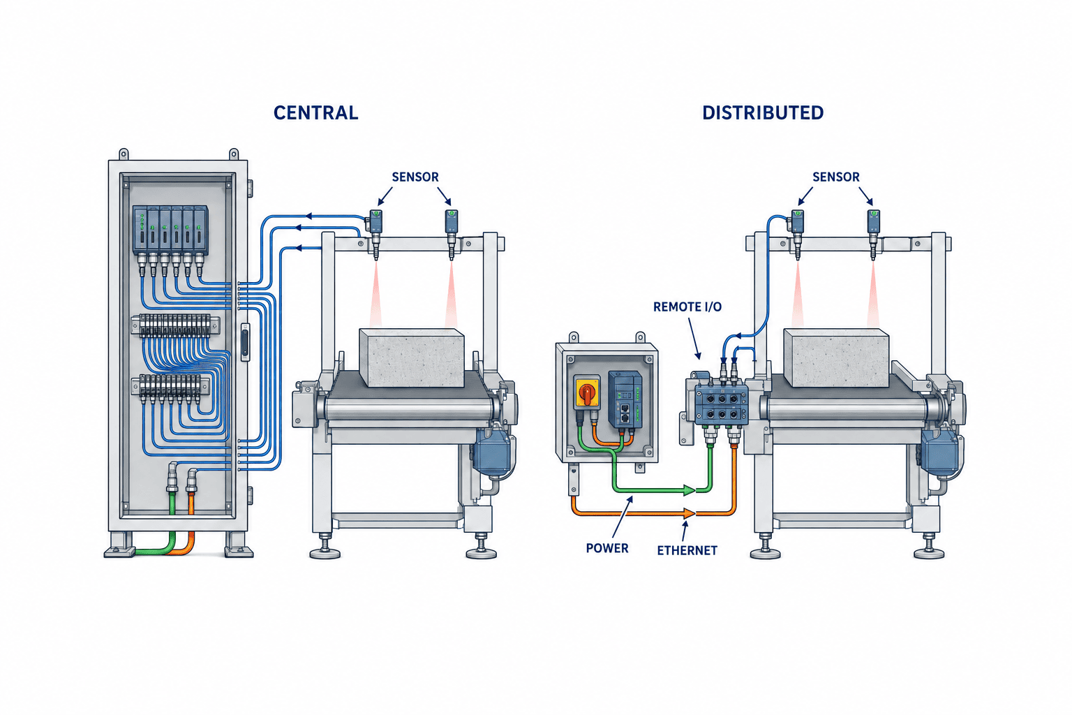
The design question is which functions move. An incoming supply, isolator, protective devices, drive, controller, safety controller, network switch, HMI and UPS can have different installation requirements. Potential machine-mounted elements include a 24 V supply, protected DC branches, remote I/O, safety I/O, sensor converters and terminal connections. Show every function on an architecture diagram, then mark location, owner, isolation method, replacement method and the boundary between suppliers. “Cabinet-free” is not an acceptance criterion by itself.
This article addresses the architecture decision before purchasing. For circuits, thermal design, documentation and panel acceptance, see our control panel design guide for Thailand. A hybrid layout, with essential protection and control in a cabinet and field I/O near the process, may be the best result.
A new machine and a brownfield retrofit start from different constraints
With a new machine, the builder can design its frame, modular stations, I/O clusters, power branches, safety zones and service access together. That can avoid assuming a large cabinet and long multicore cables. However, moving devices onto the frame can add brackets, impact guards and detours around washdown zones or hot surfaces. Compare the conventional and distributed designs on the same layout. Count cable routes, termination points, access clearance, unit changes and future expansion rather than only the cabinet footprint.
In a retrofit, the existing PLC protocol, spare ports, available 24 V capacity, drawing quality, software access, machine warranty and shutdown window are constraints. Read fault history first. If unplanned downtime is mainly caused by terminal errors and long field cables, a distributed pilot may address the cause. If the dominant losses arise from tooling, mechanical accuracy or process variation, changing the control architecture may miss the problem. Select one reasonably independent station and map every sensor and actuator to the existing I/O list, polarity, power source, response time, abnormal state and program reference.
For a retrofit, treat safety changes as a separate controlled scope, even on a small pilot. A replacement remote I/O block may change diagnostics and wiring while leaving the safety function untouched; moving a guard-door input or safe output changes the safety design and validation boundary. Record exactly which case applies. When information about the installed machine is incomplete, survey and update the as-built drawings before ordering hardware.
IP67 does not settle the environmental decision
IEC 60529 classifies degrees of protection provided by electrical enclosures against ingress. An IP67 marking does not establish resistance to every chemical, oil, UV exposure, welding spatter, high-pressure cleaning process, condensation, impact or repeated connector mating. The installed assembly includes the device, cables, branch connectors, unused-port caps, mounting position and seals. It should be assessed as a system rather than by a single device label.
Survey the actual mounting point. Record ambient temperature during production and shutdown; sunlight; cleaning agents, concentration and method; oil and coolant; dust; vibration; impact paths; drainage; condensation; and access for inspection. An exposed device may be close to a forklift, moving workpiece or cleaner’s nozzle, even though the old cabinet was protected. Confirm that a guard or shield does not make replacement impractical.
OMRON lists its NXR-S safety I/O block at IP67 with an operating ambient of −10 to 55 °C and 25–85% relative humidity without condensation. These values apply to the specified product, not every component in the solution. Collect current datasheets for the selected supply, cable, connector, sensor and bracket, then use the limiting condition in the system design. Check heat from nearby components and sunlight under realistic load. The relevant machine electrical-equipment standard, IEC 60204-1, is a reference for the project; the applicable edition and any legal or customer obligation depend on the machine, contract and destination market.
Size distributed power by branches and fault behaviour
The OMRON S8NR-S line includes 24 V models rated 90 W, 360 W and 600 W. Connector, branch-protection and IO-Link features vary by model, so the headline wattage is not a complete specification. Build a load schedule covering steady current, starting inrush, simultaneous operation, voltage drop, margin and selective protection. Determine what trips when one branch is shorted, what remains powered and how the operator sees the fault.
A device close to a station may shorten a DC run, but its AC feed, protection, earthing, cable guards and replacement procedure remain part of the project. Comparing only DC cable length with a central-cabinet design undercounts distributed work. Include AC installation, mounting, terminations, testing, spares and documentation on both sides of the estimate. During FAT, inject representative branch faults and observe unrelated I/O, recovery policy and timestamped diagnostic records. A faster fault location is only useful if maintenance staff can map a message to a physical port and restore an approved configuration.
Distinguish IO-Link diagnostics from machine safety
IO-Link can carry identification, process, parameter and diagnostic data between a device and a master. Its community’s system description explains device events and configuration exchange. Those capabilities can help replace a sensor and locate a failed port. They do not, merely by being present, validate a machine safety function. Define which information is operational, which is diagnostic and which belongs to a safety-related control path.
OMRON’s NXR-SXD1204 family is published as a CIP Safety-capable safety I/O block. Its device rating or certification does not make the complete machine meet a particular performance level. For each emergency stop, guard, light curtain or safe stop, establish the hazard, required performance, input-to-output architecture, common-cause considerations, fault detection, reset and restart rules, and validation evidence. ISO 13849-1:2023 addresses design and integration of safety-related control systems. The complete function still needs project-specific assessment and testing.
Write the communication-loss sequence into the RFP: which outputs change, how quickly, what the HMI reports, what local functions remain and whether a recovered connection can restart automatically. A catalogue statement that a device supports CIP Safety does not define these behaviours. Demonstrate representative failures at FAT and verify the installed machine and surrounding equipment at SAT.
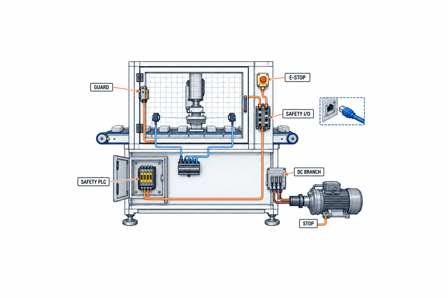
*This is a conceptual diagram. The actual safety circuit, connections and safety functions must be determined through the machine’s risk assessment, detailed design and validation.*
Measure the right unit of wiring effort
Distributed I/O can reduce individual signal wires returning to a cabinet and the work at intermediate terminals. It still needs network and power trunks, branches, protection, shielding, labels and flex-rated cables where relevant. OMRON’s “up to 66%” Smartclick wiring-effort figure should remain labelled a supplier claim. It is not a reduction factor for cable routing, frame modification, commissioning or total installation hours.
Specify connector keying and pin assignment, current rating, bend radius, shielding termination, cleaning resistance, standard and custom cable lengths, port caps and replacement stock. “M12” alone does not rule out a power/data mismatch or a bad adapter. For a fair pilot, take the same station and I/O count under both designs. Measure device count, terminations, connection operations, engineering hours, installation hours, continuity tests and rework. Separate first-unit learning time from repeat-machine time.
Compare five cost boundaries in the RFP
Send all bidders the same layout, load list, I/O list, safety requirements, environmental survey, support model and target operating date. Require them to declare inclusions and exclusions. A smaller cabinet is not a saving if its functions and costs simply reappear on the frame.
| Boundary | Central-cabinet work | Distributed work | Evidence |
|---|---|---|---|
| Design | Thermal, panel space, terminal schedule | Device placement, exposure, network layout | Drawings and engineering hours |
| Materials | Cabinet, cooling, ducts, terminals | IP-rated devices, M12 cables, guards | Modelled BOM and substitutes |
| Installation | Cabinet mounting, field termination | Frame work, trunks, brackets | Quantities and labour hours |
| Test and outage | Cabinet FAT and site wiring | Integrated FAT, site exposure and recovery | Tests and shutdown plan |
| Operation | In-panel maintenance | Field replacement, settings and spares | Lifecycle cost and responsibility matrix |
Check local stock, import lead time, alternate parts, firmware support and the customer’s right to retain configuration files. A long wait for a proprietary cable can dominate downtime; that is a scenario to calculate with actual production loss and lead times, not a universal claim. Our control panel design and manufacturing procurement guide covers the receiving, protection and documentation functions that may remain in a panel.
Turn the concept into testable RFP requirements
Define the intended operational result first: for example, a transfer and inspection module that can be moved, diagnosed and restored with specified evidence. Then issue numbered requirements for power, I/O, network, safety, exposure, maintenance, interfaces, FAT, SAT and handover. Mark any mandatory model numbers separately from areas where the integrator may propose equivalents. For each requirement, request “compliant”, “conditional”, “non-compliant” or “clarification”, together with the selected model, design evidence, test method and residual risk.
Avoid language such as “improve maintainability” without a test. A verifiable requirement might say that a failed port must be identifiable consistently at the device and HMI and that replacement must restore the approved configuration with a recorded result. For a wiring claim, compare termination operations and installation time with an agreed conventional reference. Set thresholds after measuring the local baseline, not from a marketing figure. Name the organization responsible for mechanical mounting, electrical work, controls, safety integration, software changes and support. Require as-built drawings, code, device settings, IP-address list, BOM, substitute approval rules and local-language work instructions.
FAT proves the representative architecture; SAT proves the site
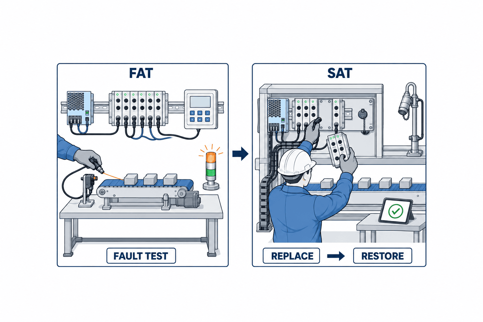
At FAT, build a representative station using the proposed devices and cables. Test normal operation and inject sensor disconnection, short circuits, branch trips, communication loss, wrong connections, device replacement, configuration restoration and restart. Map each test to a requirement ID. Validate safety functions separately against the machine risk assessment and safety specification; an individual device certificate is not a substitute. Record model and firmware numbers, wiring revisions, expected results, observations, nonconformities and retests.
FAT cannot reproduce every local condition: actual washdown, sunlight, mechanical impact routes, neighbouring equipment, network load and operators. Carry those open points into SAT and into contract payment or corrective-action gates. At SAT, inspect the real installation, cable protection, connector engagement, capped ports, voltage, earthing and network state. Use real workpieces and operating cycles. Only perform exposure tests that the selected equipment and safety plan permit.
Have local maintenance staff carry out an isolation, identification, replacement, parameter restoration and safe restart exercise. Verify their tools, accounts, backups, spare parts and Thai or English instructions. If only a visiting specialist can restore the module, the promised maintenance benefit has not been transferred to operations. Classify SAT findings by cause and owner; record interim operating restrictions and the retest needed for closure.
Four decision gates for a 90-day evaluation
A 90-day sequence can be a planning example for a substantial retrofit; it is not a promised lead time. Gate 1 confirms the target station, fault history, environment, drawing quality and conventional reference. Stop here if distribution will not address the dominant loss. Gate 2 establishes the proposed power, I/O, safety and communication architecture and checks every device’s environmental conditions. If some equipment must remain in a panel, design a hybrid layout. Gate 3 performs a representative FAT and measures wiring, setup and replacement work against the reference. Gate 4 accepts the actual machine at SAT and tests local restoration, spares and supplier support.
Each gate must permit continuation, scope revision or cancellation. Negative evidence—an out-of-range temperature, unavailable spare cable or unexpectedly broad safety modification—is a useful outcome. It may point to a smaller intervention such as remote I/O at one station or standardized field connectors rather than a wholesale redesign.
Hand over data and drawings that maintenance can use
More status information does not help if technicians cannot connect an alarm to a physical device. Provide a single mapping of asset number, model, mounting location, connector port, power branch, network identity, PLC tag and HMI alarm. A message such as “left transfer sensor fault” is inadequate if it does not identify the module, M12 port and correct spare. Use the same identifiers in drawings, labels and software. Version-control the master, I/O, sensor, power, PLC and safety-controller settings alongside the BOM, with approval, machine applicability and a rollback version. Even if diagnostics are collected remotely, retain local status and a safe recovery procedure when the network is unavailable. Remote access, retention and permissions should follow the plant’s OT rules.
At acceptance, ask technicians from different shifts to choose the spare, isolate energy, replace the device without damaging connectors, restore the approved configuration and complete a recorded restart. Fix unclear labels, missing backups, inadequate tools and instructions where the exercise fails. Keep alarm and safety-operation terms aligned across Thai, English and Japanese documents. For deployment across multiple machines, verify temperature, cable length, branch load and access on the second machine rather than freezing the pilot BOM as universal. Define what is standard, what must be engineered per machine, and how substitutes and end-of-life parts trigger revalidation.
Decision matrix: new equipment versus retrofit
| Factor | New-machine question | Retrofit question | Stop signal |
|---|---|---|---|
| Environment | Can the frame protect exposed devices? | Are measured conditions within model limits? | Heat or cleaning exposure is unknown |
| Control | Can power and I/O follow modules? | Are PLC and safety boundaries documented? | Program or drawings unavailable |
| Schedule | Can the design be repeated across machines? | Is there time for installation and recovery? | Unbounded modification scope |
| Maintenance | Are diagnostics and spares standardized? | Can local staff replace and restore? | No replacement channel |
| Cost | Is the complete machine cost compared? | Is outage loss included? | Bids have different scope |
The table is a decision gate rather than an automatic score. An unresolved safety or electrical condition should halt design approval even if the other rows look favourable. A combined architecture is a valid outcome. The recent OMRON announcement increases the options available, while the machine’s own requirements decide which option fits.
Conclusion: buy a distributed design that survives the site
Cabinet-free control succeeds when it makes a real machine easier to change, start, diagnose or maintain. For new equipment, design the layout, power, I/O and safety functions together. For a retrofit, test a bounded station after verifying the cause of loss and the modification boundary. Treat an IP marking as one part of installed environmental suitability, a CIP Safety product as one part of complete-function validation, and published labour reductions as claims to verify locally. Carry the same requirement IDs through the RFP, FAT, SAT and handover so central and distributed proposals can be compared fairly.
If you are still defining a new machine or the retrofit boundary at a Thailand plant, contact TOMAS TECH to discuss a conventional-versus-distributed comparison, an RFP outline or FAT/SAT evidence plan based on your site conditions.
FAQ
Does cabinet-free control mean no cabinet at all?
No. Selected functions may move closer to the machine while incoming power, isolation, protection, controllers, drives or operator interfaces remain enclosed. Show the proposed boundary on electrical and functional diagrams before approving the term “cabinet-free”.
Is IP67 enough for a washdown line in Thailand?
Not automatically. Check the chemical, cleaning pressure, temperature, condensation, oil exposure, installed cables, connectors and port caps. Match the precise models and installation to the measured site conditions.
What should a retrofit assessment inspect first?
Fault history, as-built circuit and I/O lists, PLC and safety-system editability, spare power, mounting exposure, shutdown window and maintenance capability. Verify that field wiring is actually a significant source of loss before changing the architecture.
Can a published 66% wiring reduction go into the payback model?
Not as a guaranteed project-wide saving. It is a supplier figure for a connector approach. Measure installation, routing, testing, correction and documentation on a representative station under the same scope for both designs.
Does a CIP Safety-capable I/O device certify the whole machine?
No. The complete safety function needs a risk assessment, required performance, architecture, failure and restart behaviour, and validation evidence for the actual machine and applicable market.


